Creating Kitchen layout, Hatching of Architectural elements and sectional view of an Industrial Building in AutoCad
Drawing1:
Aim:
To draw the Kitchen layout and provide hatches.
Introduction:
The Kitchen layout is constructed as per the Standard dimensions given by Code, the Furniture & Plumbing elements are mentioned in the drawing to optimize the space in the kitchen and to allow sufficient light and ventilation into it.
Procedure:
While drawing the Layout various commands were used.
In order to get the asthetic apperance some more commands like hatching,Gradient are also used with different colours.
The Commands used are
Line command
Xline command
Offset command
Trim command
Circle command
Extend command
Dimstyle manager
Dimlinear command
Dimangular command
Hatch command
Gradient command
Layers command
Block command
Insert command
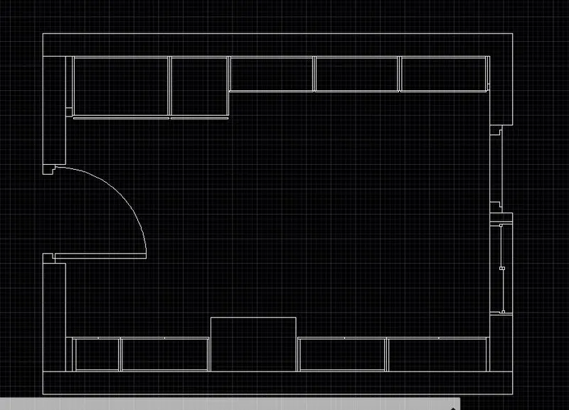
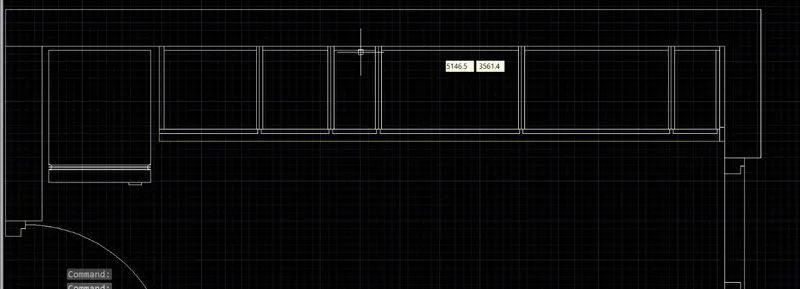
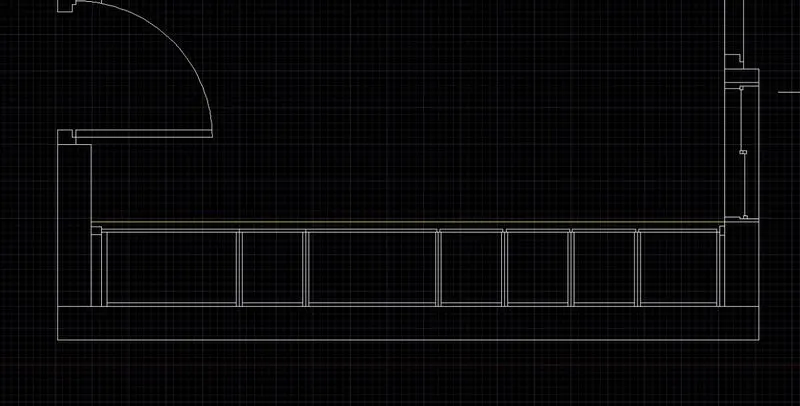
Dimstyle manager: In this all the required adjutments like (Arrow size Text size Fit and Primarary units were takenas millimeters) are made to fit the drawing size.
Hatch command : Necessary settings to hatch the wall using ANSI CODE hatch settings
To hatch the elements different userdefined settings were used
Gradient:Proper gradient for asethic looking is selected which is suited for the elements like wall,door and windows
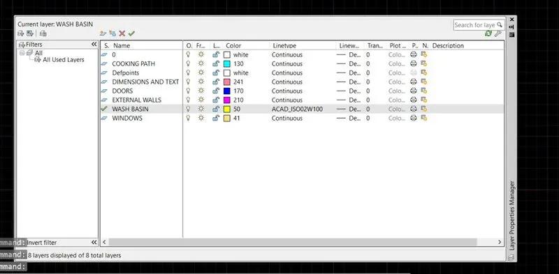
Layers command: Using this Layers were created for different elements to identify them by giving them different colours and Lineweight,Linetype properties
Block command & Insert command:Blocks are created for the doors and windows which can be used directly using the insert command.
Result:
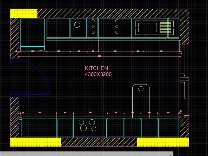
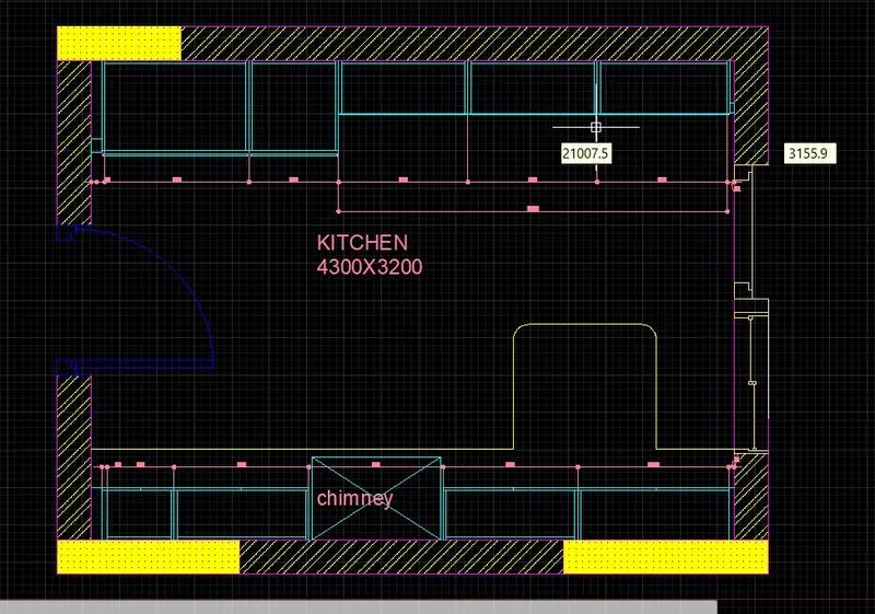
The final result after applying all the commands..
Drawing2:
Aim:
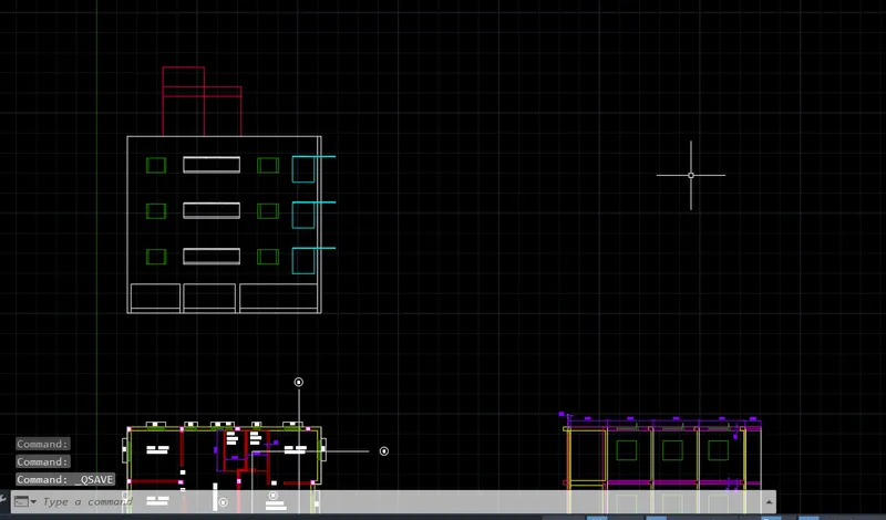
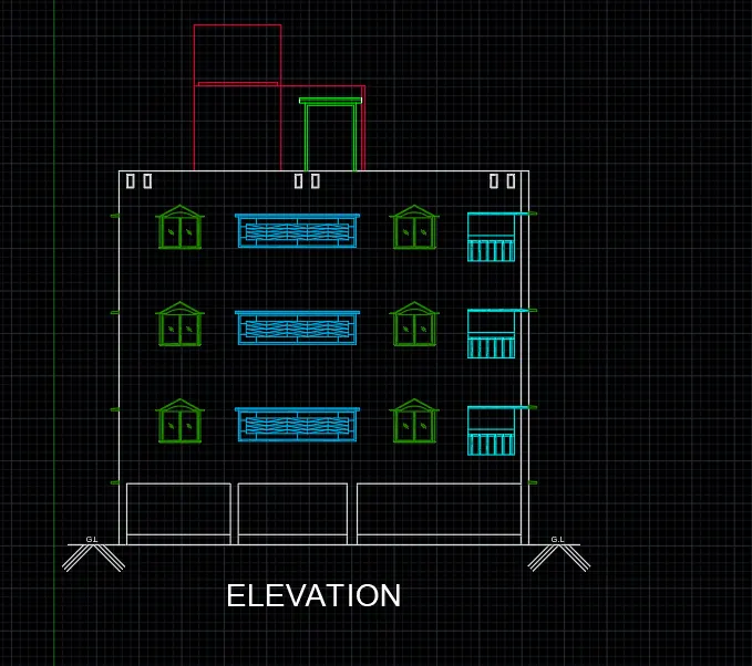
To Draw the ELEVATION OF THE BUILDING which already having the plan and sectional view.
Introduction:
The Elevation of the building is created using various commands for ease and to have the asethic look of the Drawing.
Procedure:
The elevation of the Building is started with the Natural Ground level,
then it is taken for offset to draw other levels like
Plinth level
Sill level
Lintel level
Slab level
Parappet wall
Based on these levels the Building structure is framed with Doors,windows, Sunshades,steps and other elements
The levels are taken based on the Standard Levels or Design Engineer levels which are given by him.
Commands used for drawings are:
Line command
Offset command: Mainly to determine the difference of the levels
Copy command
Trim command
Dimstyle manager
Dimlinear command
Extend command
Hatch command
Gradient command
Layers command
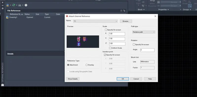
Xref command
Xclip command
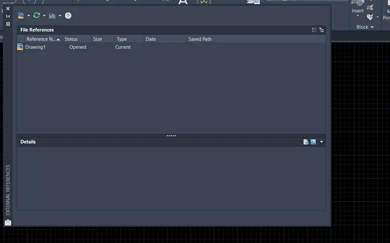
Xref command: This command helps in attaching the other drawing in the workspace of the current drawing
Using this command
- the extension lines can be drawn,
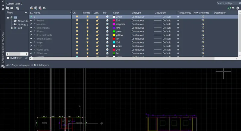
- Layers can be utilised which are previously created,
- All the references related to colour,Text,Size,Shape,Linetype,Lineweight etc can be captured and used in the current drawing
- Also it is used to make changes in the Xref plane or creating new elements
- New layers of same name or different names using ATTACHMENT or OVERLAY OPTIONS
- It is also used to select the Relativepath of the drawing.
- When the Xref document is modified then the doucment can be modified in the current drawing by using RELOAD option
Xclip command: It is used in creating clips of the Xrefed (External reference) .dwg Drawing
The clipping can be of any shape and made for ease in identification and the checking of the required element's Dimension or clour or shape etc
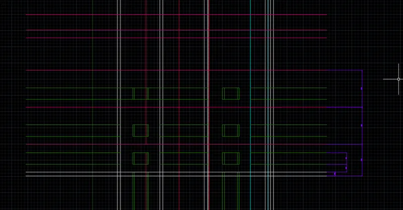
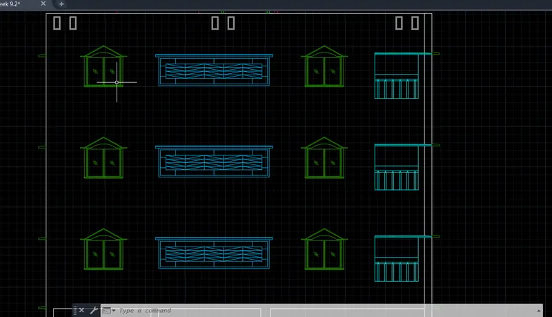
Hatch command : It is used for hatching of the elements to identify them,Hatching is done for Doors, windows sunshades walls which are elevation for having a pleasant look in the drawing and in the way for ease of understanding
Gradient: The elements were given particular gradient to have the most desirable look in the elevation and colours are choosed by mixing one or more to the required look.
Layers : Layers are created for Differentiating the elements for the purpose of ease of drawing
Blocks : Blocks for Doors and windows are created and then inserted (for the view in ELEVATION).
Result:
Drawing3:
Aim:
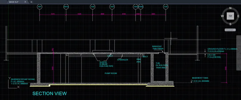
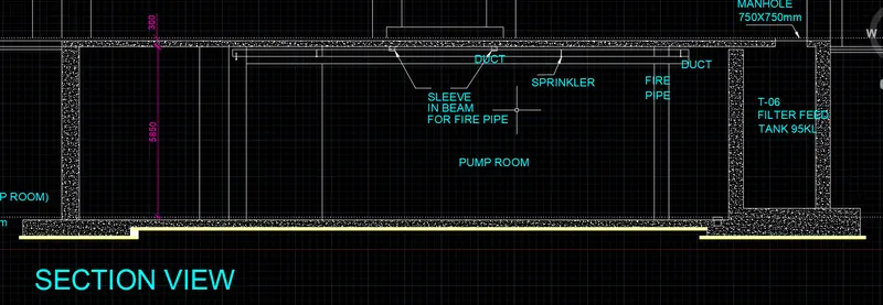
To draw the given SECTIONAL VIEW of the Industrial Building
Introduction:
For Industrial Buildings the TOOL like AUTOCAD is very much useful in creating the suitable structural drawing elements,
Various Industries have been using this software for creation of the ARCHITECTURAL AND STRUCTURAL DRAWINGS.
Procedure:
For Drawing the SECTIONAL VIEW of the Industrial Building we start with the Levels and the important elements which can be represented using the various commands
Commands used are:
Line command
Xline command
Offset command
Trim command
Extend command
Dimstyle manager
Dimlinear command
Layers command
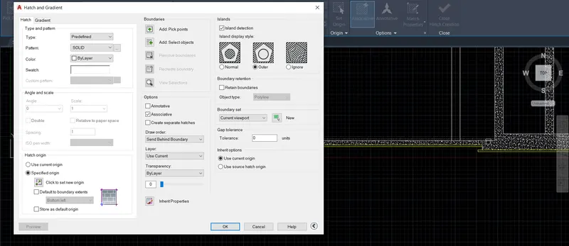
Hatch command
Gradient command
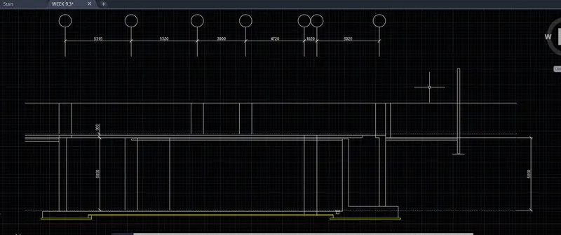
The elements like Duct,Pump room,Fire hose etc are shown by creating them with diffent colours.
The walls of the sectional view are JOGGED and represented as shown in the diagram or as per the requirement.
The walls of the view are Hatched & suitable Gradient is applied to have the plesant apperance andto create ease of Understanding.
Result: