Creation of Multiple viewports, Scaling the drawing and setting in Template in AutoCad
CREATION OF MULTIPLE VIEWPORTS, SCALING THE DRAWING AND SETTING IN TEMPLATE IN AUTOCAD:
INTRODUCTION:
Layout viewports are objects that display views of model space. You create, scale, and place them in paper space on a layout.
On each layout, you can create one or more layout viewports. Each layout viewport is like a closed circuit TV monitor of a view of the model at a scale and orientation that you specify.
CREATE LAYOUT VIEWPORTS-
Use the MVIEW command to create a new layout viewport, specify the view that you want to display in it with one of several methods:
- Click the diagonal corners of a rectangular area, and the extents of model space are displayed automatically.
- Specify the Named option to use a previously saved model-space view.
- Specify the New option for temporary access model space to define a rectangular area.
- Choose the Object option and select a closed object such as a circle or closed L-shaped polyline to convert into a layout viewport.
MODIFY LAYOUT VIEWPORTS-
After creatING a layout viewport, can change its size and properties, and also scale and move it as needed.
- For control of all the properties of a layout viewport, use the Properties palette.
- For the most common changes, select a layout viewport and use its grips.
LOCKED LAYOUT VIEWPORTS-
To prevent accidental panning and zooming, each layout viewport has a Display Locked property that can be turned on or off. You can access this property from the Properties palette, the right-click menu when a layout viewport is selected, a button on the Layout Viewports tab on the ribbon, and a button on the status bar when one or more layout viewports are selected.
1. AIM:
To create a layout of the Plan and Section A of the project in Challenges 7, using the template TutorialmArch.dwt in a scale as given in the Figure. Use the MV command to create the viewport of the size as
shown in Figure. Also, use ATTEDIT command to edit the information in the title block. Use A1 size for the layout and take a plot
PROCEDURE:
- To create the viewport, take the 7th week challenge that is already created and keep plan section A-A from the drawing
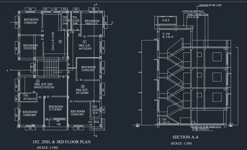
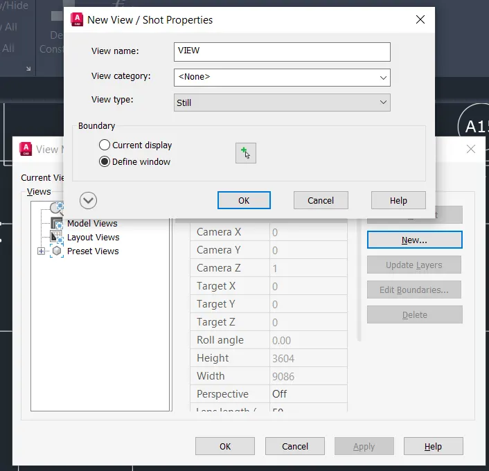
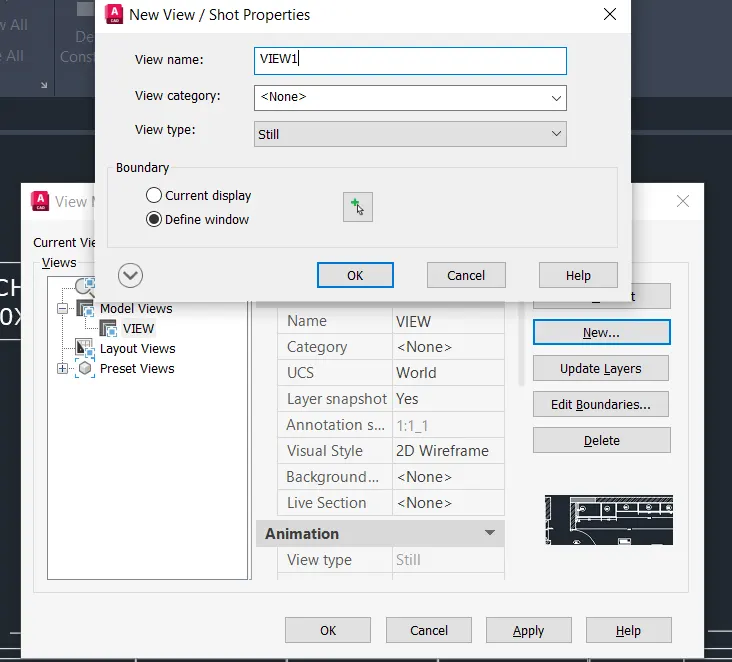
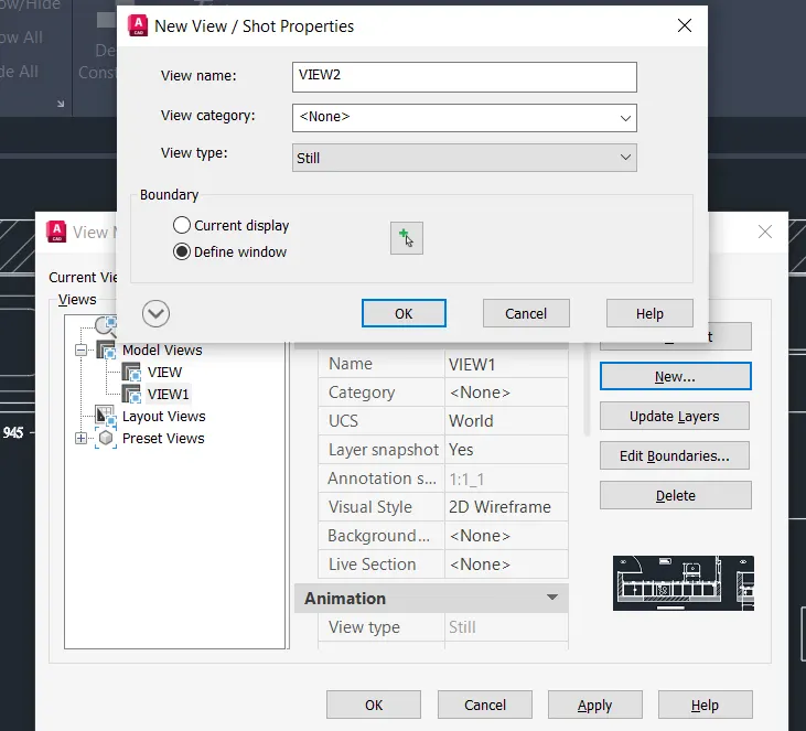
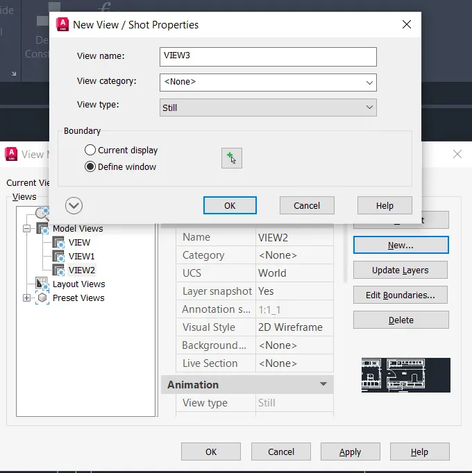
- Take view command to create the model of the plan and section
- Then give the view name and take boundary option as define window
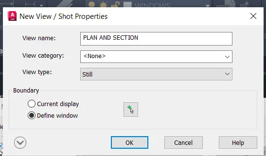
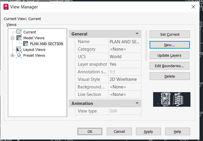
- Now, click ok then apply and again ok
- The model view is created
- Now take layout command and select template. From the template select the Tutorial-march and isert it

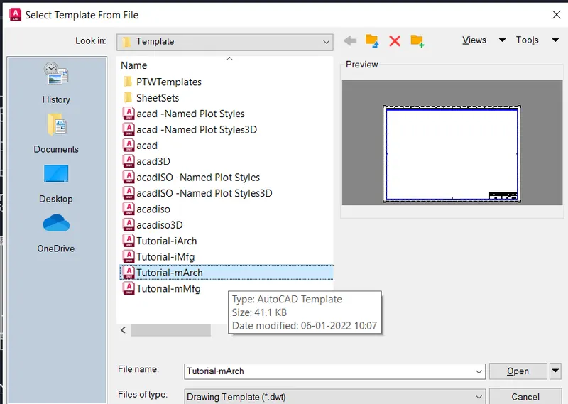
- Hence a new layout is created with the template
- Now, type page setup and page setup manager dialogue box opens
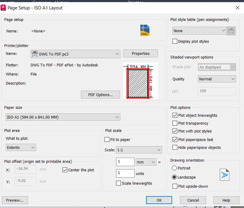
- Modify the settings and close the dialogue box
- Now, use the MV command and create the multiple viewports as given
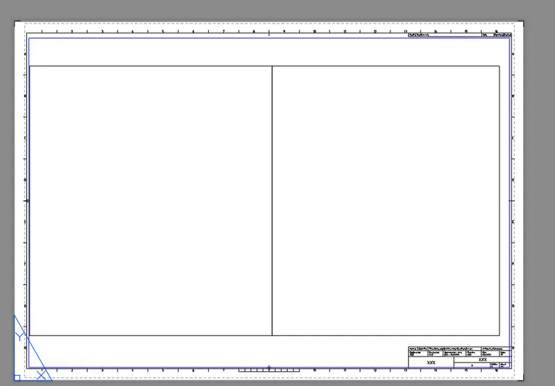
- Now, type MS in command box to zoom in and zoom out view in the viewport and PS command to return back to paper space where zomm in and out is not possible
- Select MS command and select first viewport and zoom in the plan and give scale of 1:50 and repeat the same procedure for second viewport and zoom in section A-A
- Using text command write the scale 1:50 in the paper space
- Use ATTEDIT command to edit the information in the selected template
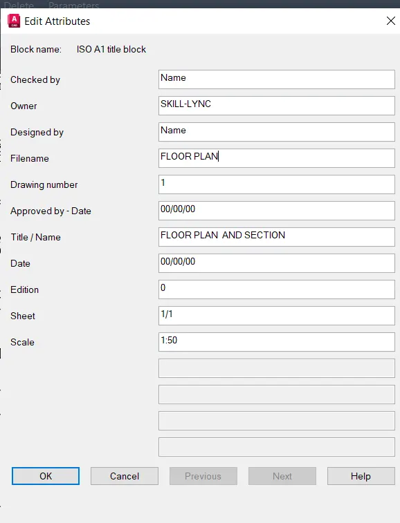
- Now, we have to plot the drawing. select pagesetup command and give dwg to pdf and then click ok
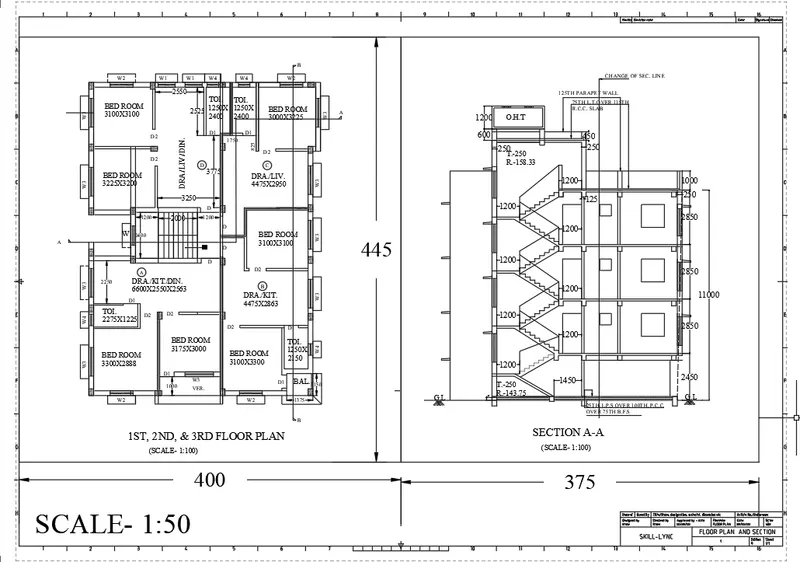
2. AIM:
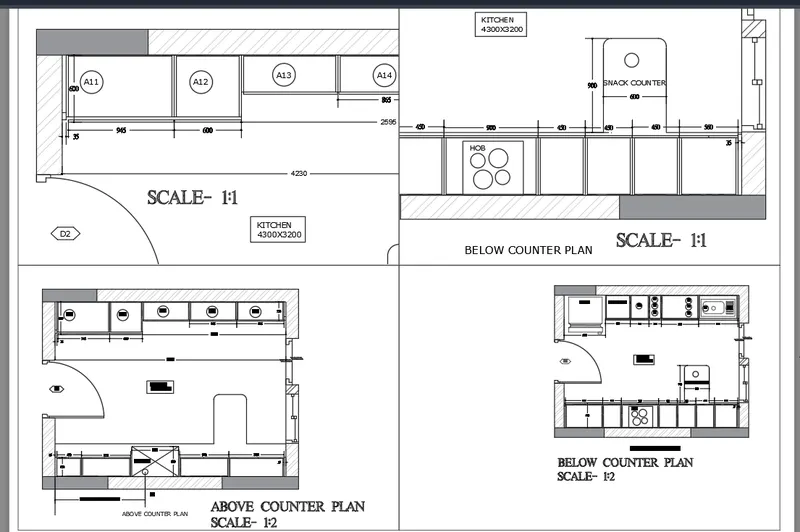
To create a layout of the Kitchen drawn in Challenge 9 as shown in Figure. Use the scale as shown in the
Figure. Use A4 Size page for the layout and take a plot
PROCEDURE:
- To create the viewport, take the 9th week challenge that is already created and keep plan kitchen plan from the drawing
- Now take layout command and create a new layout and rename it as Kitchen
- Select view command and create the required views to display in the layout
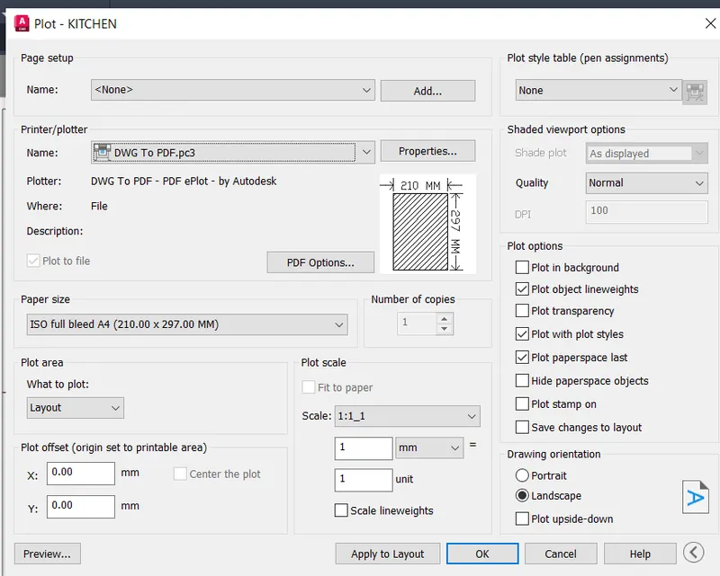
- Now, type page setup and page setup manager dialogue box opens and modify the settings as given
- Now, use the MV command and create the multiple viewports as given
- Now, type MS in command box to zoom in and zoom out view in the viewport and PS command to return back to paper space where zomm in and out is not possible
- Select MS command and select the viewports and give scales as given
- Using text command write the scales in the paper space
- Now, we have to plot the drawing. select pagesetup command and give dwg to pdf and then click ok
3. AIM:
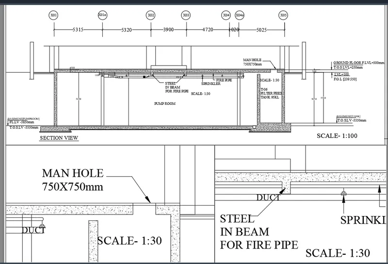
To create a layout of the section created in Challenges 9. Use scale as mentioned in the Figure. Use MV command create multiple viewports and take a plot
PROCEDURE:
- To create the viewport, take the 9th week challenge that is already created and keep plan section view of industrial drawing
- Now take layout command and create a new layout and rename it as Industrial drawing
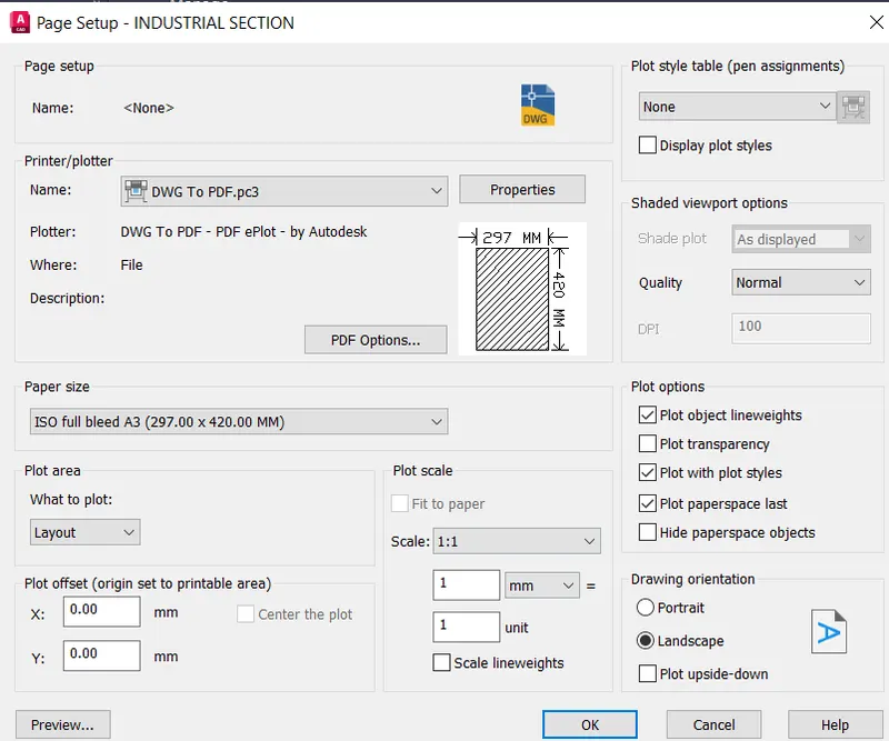
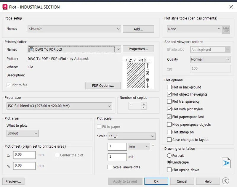
- Now, type page setup and page setup manager dialogue box opens and modify the settings
- Now, use the MV command and create the multiple viewports as given
- Now, type MS in command box to zoom in and zoom out view in the viewport and PS command to return back to paper space where zomm in and out is not possible
- Select MS command and select first viewport and zoom in the plan and give scale of 1:100 and repeat the same procedure for second viewport and third viewport with scale of 1:30
- Using text command write the scales in the paper space
- Now, we have to plot the drawing. select pagesetup command and give dwg to pdf and then click ok
RESULTS:
1. The layout of the Plan and Section A of the project in Challenges 7 is
2. The layout of the Kitchen drawn in Challenge 9 is
3. The layout of the section in Industrial drawing created in Challenges 9 is