Project 1 _Creating an Architectural plan for the provided plot size and develop relevant basic structural drawings
Design and Draft a layout of a residential building with the following details:
a. Plot Size: 60’x20’(18.3m x6m)
b. Orientation- Facing East
c. Develop the following:
1. Architectural Drawing (Floor Plan, Elevations, and Sections).
2. Structural Drawing (Column, Bean, Footing Plan).
ARCHITECTURAL AND STRUCTURAL PLAN OF A TWO STOREYED RESIDENTIAL BUILDING
Aim : To draw :
1. Architectural drawing of a residential building:
a. Plot of residential building.
b. Plan of a two storeyed building.
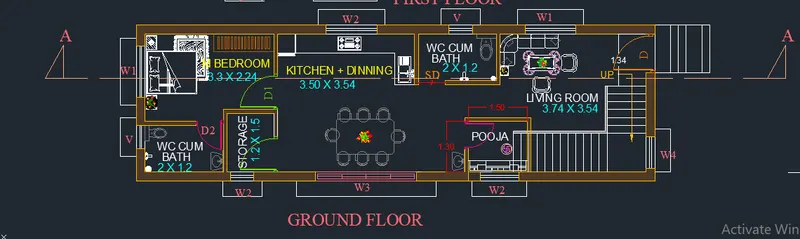
A. Ground floor plan.
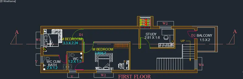
B. First floor plan.
c. Elevation of a two storeyed residential building
d. Section of a two storeyed residential building
2. Structural drawing:
a. Column plan layout of the building
b. Beam plan layout of the building
c. Footing plan layout of the building
Commands used:
a. Line - Command "L" . Give the distance.
b. Offset - Command "O". Give the distance and select the line from where offset is to be done.
c. Rectangle -Command "REC". Click on dimnesion, enter the length and width .
d. Trim - Command "TR". Click on the line from where to be trimmed and then click on the line to be trimmed.
e. Extend -Command "EX" . Click on the line to which it has to be extended,then click on the line to be extended.
f. Block - Command "B" . Give name for the block , pick a point of the object, then select the object.
g. Blockedit -Command "BEDIT" . It is used to give parameters and actions to the block . For eg: to flip a door.
h. Dimension - Command "DIMLINEAR". select the points where dimension is to be marked . "DIMCONTINUE" is used to give dimensions continously,without selecting the base point each time.
i. Layer - Command "LAYER". It is used to assign different properties to different elements in a drawing so that it is easy to work on each element .
j. Hatch - Command "H". Used to define the material property . Select the pattern and pick the object where hatch has to be displayed.
k. Design centre- From the insert toolbar. Use to insert the furnitures etc in drawing ,they are predefined blocks
l. Layout - Layout is created in layout tab . To set the drawing before printing
m. Multiview- Command "MV" - used to create viewport
n. Model space and paper space - Command "MS" and "PS". MS-to adjust the scale ,viewof drawing in model space . In paper space we can change the size of viewport etc.
o. Plot - Command "PLOT" . Used to print the drawing , we can convert the drawing to pdf as well. Pen assignments in plot helps in make the printin black colour ( monochrome), grey scale or the colour of layer and line weight can also be adjusted befor print.
PROCEDURE :
Step:1 Opening of Autocad ,setting limits
- Click on autocad aplication
- command : QNEW
- select the metric system
- click on ADVANCE SETTING
- Unit : decimal precision 0.00
- click on NEXT
- angle : decimal precision 0
- angle measure : EAST
- Angle direction : counter clockwise
- area : 100x100
- press : ENTER
- command : UN
- select decimal
- unit m
- press : ENTER
- All dimension in m
1. Architectural drawing of a two storeyed residential building
a. Plot of residential building.
Step:2 Drawing the plot, and giving setback.
- Given plot size as 18.3m x6m.
- Mark the direction N,S,E,W.
- By rectangle ,draw the plot giving dimensions as 6 and 18.3 m.
- Give setback from the plot , front- from the road 3m ,2m for the backyard, 1m for the sides.
- The proposed building should come inside the setback drawn.
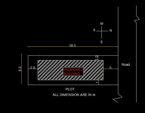
b. Plan of the residential building
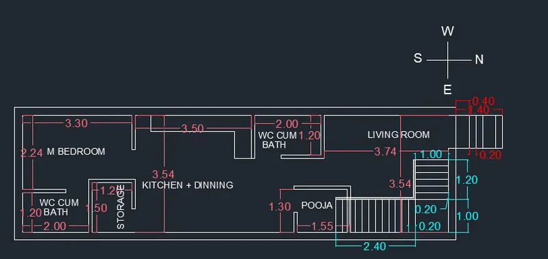
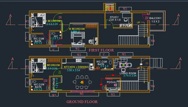
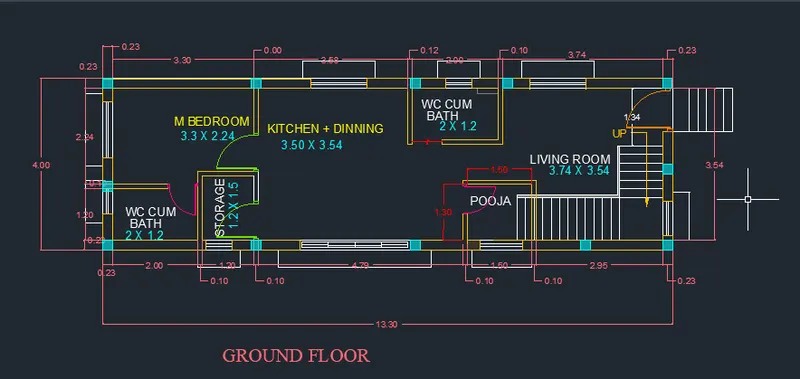
A.Ground floor plan:
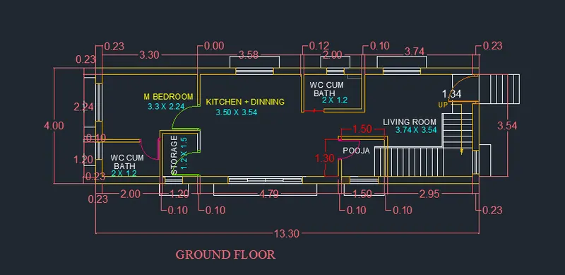
Step:3 Drawing wall
- Offset 0.23 m from the boundary after the setback is taken for the wall thicknes
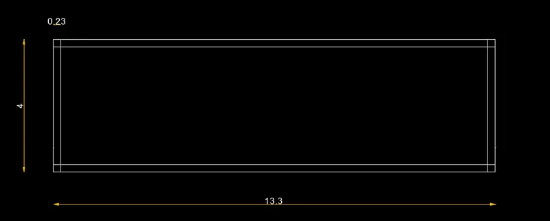
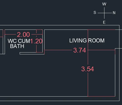
Step:4 Drawing Living room and WC cum Bath :
- As the orientation is given as North, main door should face West - South.
- For living room and wc, give 3.74m, 0.1m and 2m, 0.1m offset horizontally from the North side
- The size of the room will be 3.74 x 3.54 m. and 2 x 1.2m for wc and cum bath.
- Opening for maindoor is create by offseting 1m from the wall and trim the same.
- smilarly create door opening for wc is 0.9m
- As per Vaasthu Shastra, North is favourable for living room and the entrance should face North or East.
- North -East should be avoided for toilet as per Vaasthu Shastra.
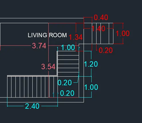
Step:5 Drawing Staircase and entrance stair:
- From North wall of living room, draw an offset of 1m for the width of the stair, also offset 1m from the West wall for the width of 2nd flight.
-Stair dimension: tread-20cm
rise - 16.5cm
Width - 1m
Total no: of steps -18 steps
- From 1.34 m from the main door wall , start drawing the steps
- Draw 6 steps in the first flight offseting 0.20m.
- Draw the landing of 100cm width.
- For the 2nd flight steps , again offset 0.20m and draw 12 steps.
- Again offset 0.05 in west direction of staircase as a handrail
- Also From North wall of living room, draw an offset of 0.4m,0.2m,0.2m,0.4m and 0.2m for the width of the stair, in outer directon
- Stair dimension: tread-20cm and 40cm
rise - 20cm
Width - 1m
Total no: of steps -5 steps.
Step:6 Drawing pooja room:
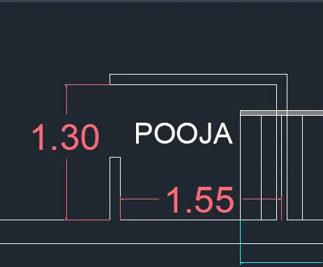
- Again offset 1.55m from the living wall for pooja room.
- Width will be 1.3m
- Size of dinning room is 1.55x 1.3 m.
- Create a door opening of 0.8 m on the south wall of pooja room.
Step:7 Drawing Kitchen +dinning :
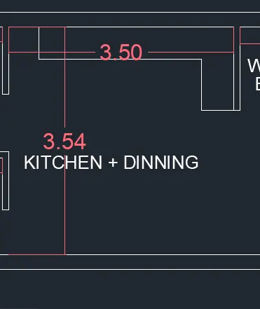
- Offset 3.50m horizontally from Bath wall and 3.54m vertically .
- The size of kitchen is 3.50 x3.54 m.
- Acoording to Vasthu Shastra the kitchen north or north- east is not preferred. because it is good for only some people or especailly women.
Step:8 Drawing store :
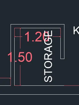
- Draw horizontal offset of 1.2m from dinning wall .
- Give vertical offset of 1.5m.
- Give wall thickness of 0.12m.
- making door opening 0.8m
Step:9 Drawing Master bedroom and toilet:
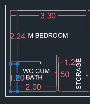
- From the South wall offset 3.35m and width of 2.24m joining the kitchen wall.
- The size of bedroom is 2.24x 3.35m.
- According to Vaasthu Shastra South- West is ideal for Master bedroom.
- Create opening of 0.90m by offset and trim commands.
- For toilet, draw an offset horizontal of 2m from the store wall.
- Size of toilet is 2 x1.2m.
- North-East should be avoided for toilets according to Vaasthu Shastra.
- Trim the excess lines and fillet the corners.
Step:10 Inserting text:
- With multiline text , draw the text box, text height as 0.20m and style as arial.
B. First floor plan
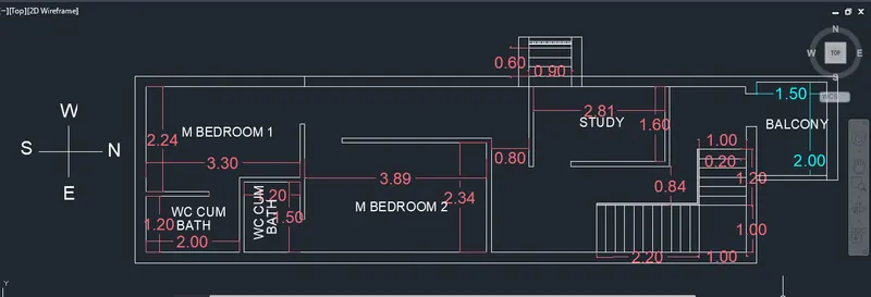
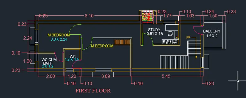
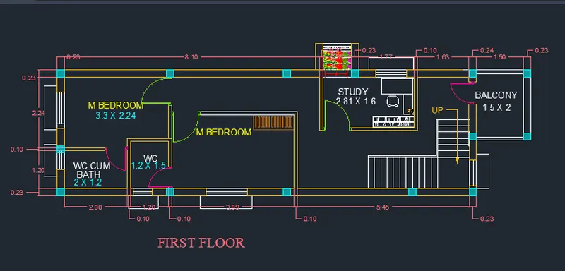
Step:11 Drawing first floor rooms and toilet:
- Copy the plan and delete all the walls except the stairs.
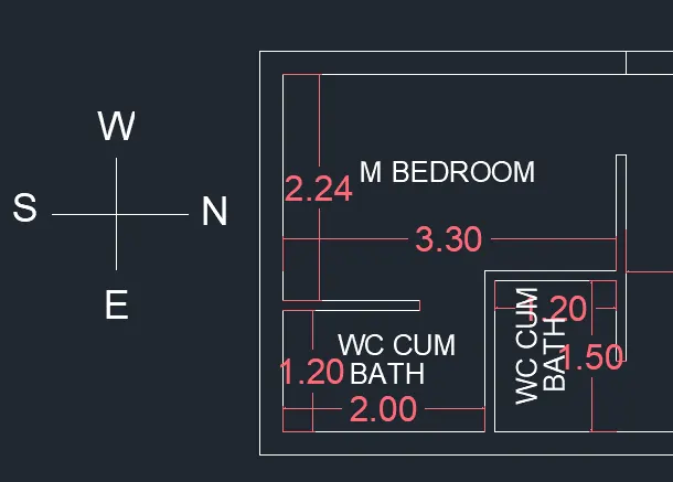
- Two bedrooms are drawn on top floor.
- From the south wall draw an offset of 3.35m and width of 2.24m vertically.
- Draw toilet of size 1.5x1.9m.
- Trim the opening of door 0.9m for room and 0.7m for toilet.
- South-West is best for rooms as per Vaasthu Shastra.
Step:12 Draw the other room next to the 1st room.
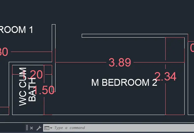
- To draw room offset 1.2m And 3.89m horizontally from wall of toilet and 1.5m and 2.34 vertically.
- Draw toilet by offseting , 1.2m horizontally from the room drawn and 1.8m vertically.
- Draw the partition wall thickness as 0.1m.
- Create opening for doors 0.9m for room and 0.7m for toilet.
Step:13 Draw the Study room:
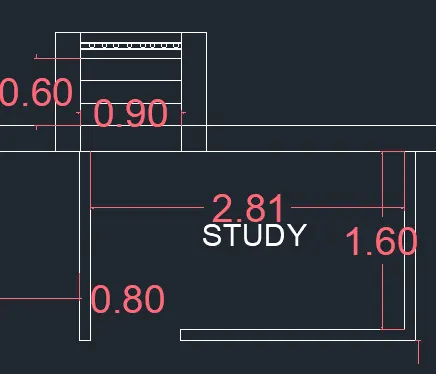
- Draw horizontal offset of 0.8m from M. Bedroom2 wall for opening passage. Again offset 0.1m and 2.81m from last offset for study room.
- Give vertical offset of 1.6m. from outer wall
- Give wall thickness of 0.1m.
- making door opening 0.8m
- Also draw the tree gallery having size is 0.9 x0.6m having wall size is 0.23m.
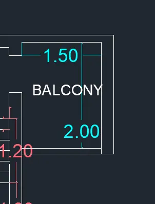
Step:14 Draw the Balconey:
- Draw horizontal offset of 1.5m from outer wall from north direction .
- Give vertical offset of 2m.
- Give wall thickness of 0.1m and 0.23m.
- making door opening 0.7m
Step:15 Inserting text
- With multiline text , mark all the rooms with text height 0.2m and style as arial.
Creating doors and windows and making them as block:
Step :16 Assuming the size of doors and windows , creating them as block and inserting them.
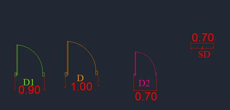
- Assuming the sizes of doors as: D - 1 x 2.1 m
D1 - 0.90 x2.1m
D2 - 0.70x 2.1 m
SD - 0.7 X 2.1m
- D1 for main doors, D2 for bedroom doors and D3 for toilet doors.
- For door, draw a rectangle of 0.038 x0.076 m for frame.
- Copy this rectangle at a distance of 1m from the frame for door D. ( as the opening is 1m ).
- From the midpoint of rectangle ,draw a horizontal line 0.01m for hinge .
- Draw a vertical line from this point for the frame and offset 0.01m for the thickness .
- Create a circle from the hinge ,meeting the midpoint of the frame of other side.
- Extend the vertical line to the circle.
- Trim the unwanted portion of the circle.
- D is created and make it as a block D.
- Similary create D1 ( 0.9m distance in between frame)and D2 ( 0.7m distance in between frame) and make it as blocks.
- Insert the block of doors in respective openings.
- Create a sliding door for the common toilet, opening 0.70m.
- Command "BEDIT" edit block defenition dialogue box appears , give the parameteer as flip , then give the axis of flip , here both vertical and horizontal axis are given.
- Two flip states are created here.
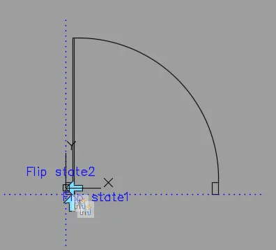
- Select action as flip , then select the parameter, then the object.
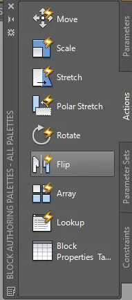
- Use test block to test the flip if it is working or not.
- We can flip the door accordingly while placing.
- Assuming size of windows : W1 - 1.3 x1.5 m
W2- 1 X 1.5m
W3 - 2.58x 2 m
W3 - 0.8x 1.5m
V- 0.60x0.50 m
- For window, draw a rectangle of 1.3 x 0.23m for frame.
- Draw a line of 1.30 m for W1 and mirror the rectangle on the other side.
- Delete the line, draw another line connecting the midpoint of the rectangle
- Offset 0.015m from the middle line to two sides
- Divide the panel into three for W1.
- Similarly draw 1m for W2 and 0.60 for V. and 2.58 for w3
- Divide the panel into two for W2 and one division for V.
- Make W1, W2 and V into blocks.
- Insert them where ever required.
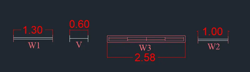
- Place this windows and doors at required place.
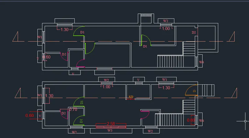
Use of Layer
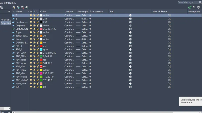
Step:17 Different layers are made and the objects are placed in layers
- Click on layer, layer manager dialogue box apperas.
- Create new layer button and create the layer for walls,stairs, doors,windows,text,dimension.
- Insert the respective elements in the layer.
Dimensioning:
Step:18 Inserting the dimensions
- Command "DIMLINEAR" and select theline of which dimension is to be found.
- Use command "DIMCONTINUE" for repeated dimensioning.
- Suppress extension lines ,give colour to the dimension line, text height as 0.25.
- Command "D" is used for editing the dimension.
Hatching:
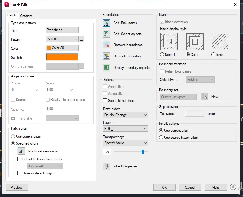
Step:19 Objects are hatched to show thier material property.
- Hatching is done for brick and open terrace.
- Solid having transparency scale is 79.
- Hatch edit is selected and the colour of hatch is changed to 30.
Inserting furniture by design centre:
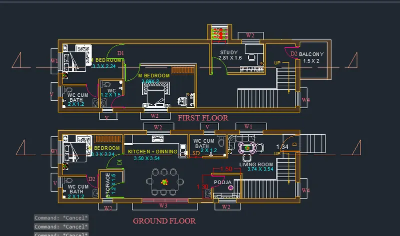
Step:20 Design centre
- With the help of design centre ,insert the required furniture in the plan.
- Also section line is shown.
c. Elevation:
Step:21 Projecting lines to draw the elevation
- Project the wall lines to the top.
- Draw an horizontal line .
- Offset 1 m for the plinth level after this 1m divide in 5 section for staircase having width is 1.30m
- Offset 3.15m for the first floorlevel.
-Again offset 3.15m for the second floor level.
- For terrace head room give offset 2.54m and 1m for parapet wall.
- Trim all unwanted lines
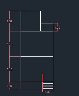
Step:22 Drawing windows and doors in elevation
- For windows and doors, project the windows from the plan and give a height of 1.2m (for W4 in staircase)respectively.
- For doors project the door and give a height of 2.1m.
- Project the shades and draw the shades at top of the window level.
- Trim off the extension lines and make shutters and panels for doors and windows
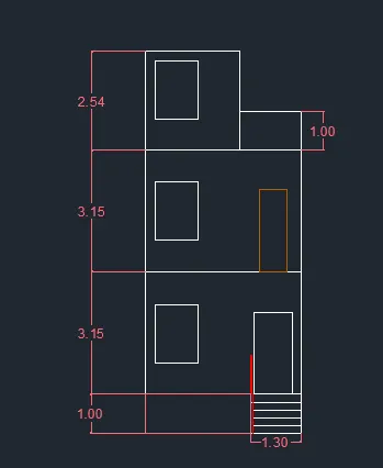
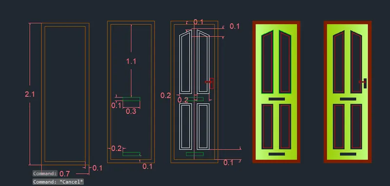
I) FOR DOOR D:
- For D entrance door , create a rectangle,offset 0.05m, 0.1m, and 0.05m
- For top panel draw rectangle 0.7 x 1.1m then offsetting 0.13m and 0.02m inside of rectangle. Also draw arc by using circle having radius are 0.18 and 0.13m then trim off athoer portion of circles.
- For bottom panel draw rectangle 0.7 x 0.5m, Again draw rectangle size 0.13 x 0.10m and place it from 0.13m from right side and copy it by using array and place. Draw circles in between of rectangles having radius is 0.06m
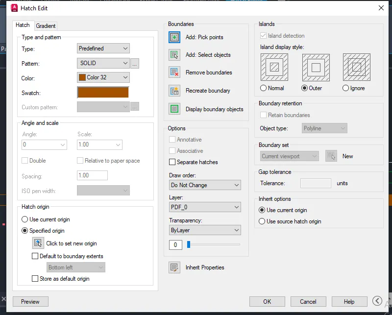
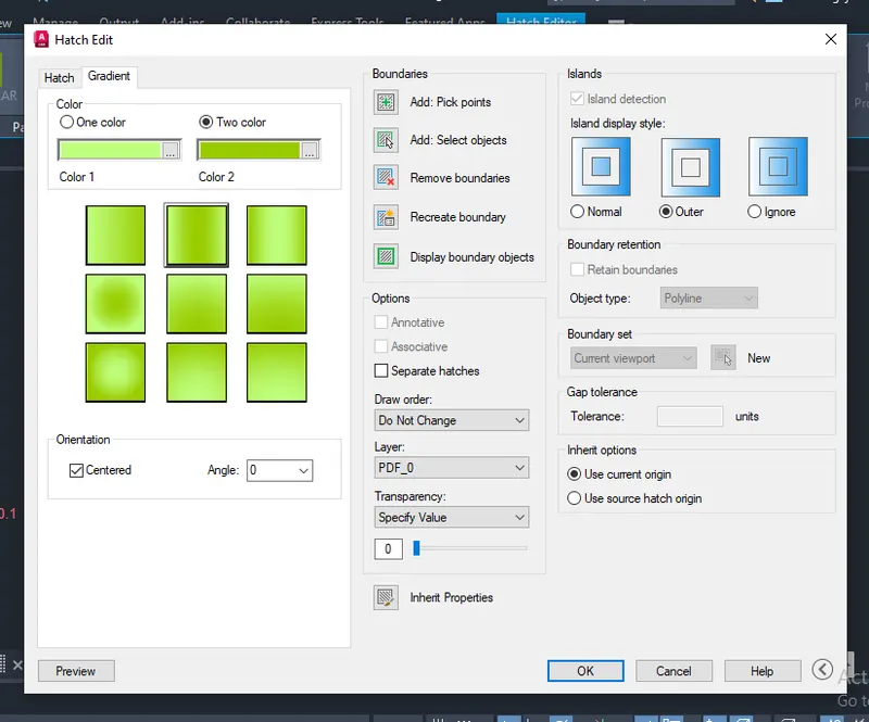
- Then design hatching using solid pattern.
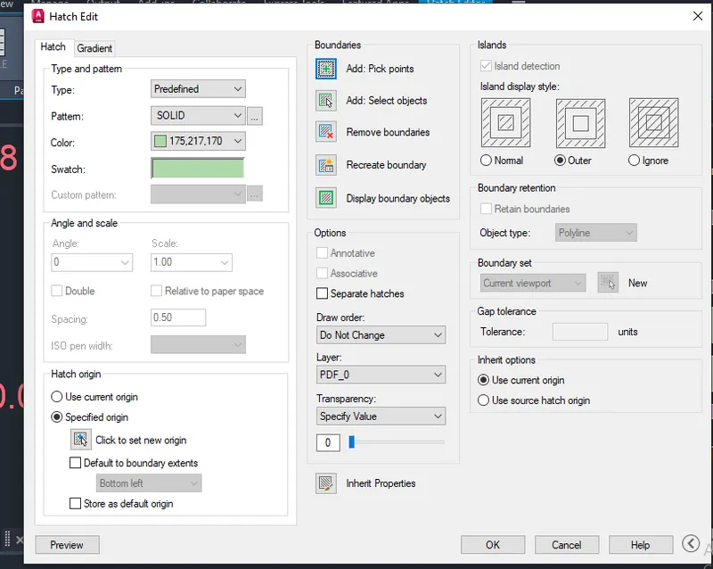
- Similarly used other hatched for differnt objects.
- draw handle by using circle, line and arc.
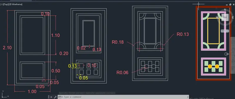
II) FOR DOOR D2:
- For D2 entrance door , create a rectangle, offset 0.1m, Draw rectangle 0.3 x 0.1m place this rectangle from top 1.1 and from bottom 0.2
- For top panel draw line from centre give offset 0.04m draw rectangle 0.18 x 0.95m and 0.87join this both sides by inlcined line. Then offsetting 0.1m.
- For bottom panel draw rectangle 0.18 x 0.68m, give offset 0.1m.
- Draw handle.
- Then design hatching using solid pattern.
III) Draw Window:
- For window W4 height 1.50m and 1.1 as a width , draw an offset of 0.1m for the thickness of lintel on 3sides .
- Draw a rectangle offseting 0.1 for on 3 sides the frame .
- Now draw line at midpoint then give offset 0.01 both side of line.
- Again offset 0.02m from the last offset for the shutter,give 0.05m thickness from right and left side of window frame..
- Draw rectangles having size is 0.36 x 0.15m which is making as a glass and place it by using copy- array option.
- Using hatching for glass, frame and lintel thickness.
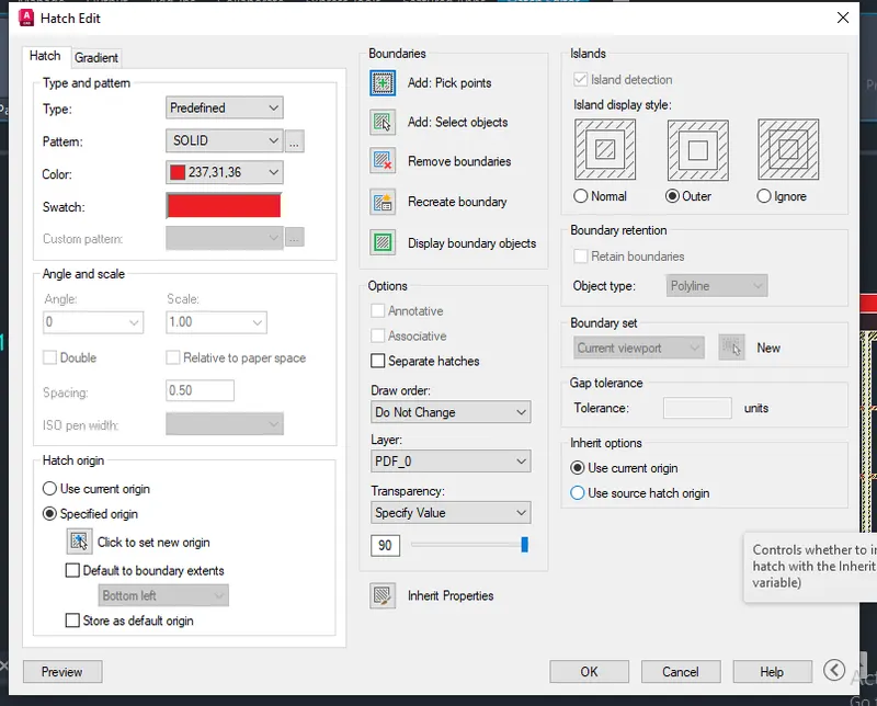
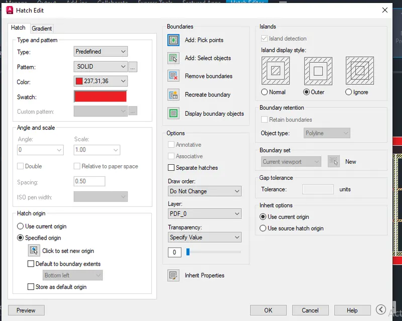
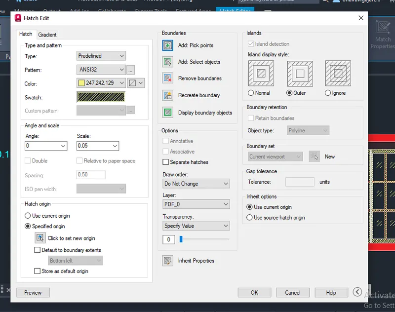
- Hatch the window with GHOST GLASS scale -0.01(V) and 0.05 (w)
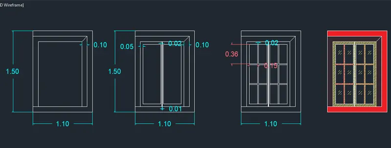
- Place the doors and windosw its required position.
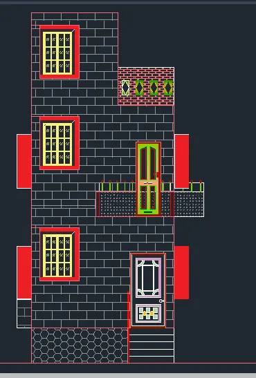
- The sill level is 0.8m from plinth level.
- For architectural purpose,create some hatches to walls.
- Create a balconey having height is 0.95m.
- Draw other lintel projection by drawn the XL at vertical trim this lines.
d. Section :
Step:23 Section of ground and first floor
- Section line of ground and first floor plan, section A-A.
- Project the lines from the elevation for the height and from the section line of plan for the horizontal members.
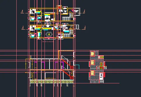
Step:24 Drawing windows ,doors and stairs in section
- Draw the window and door which we see after cutting the section line. Show thickness of them by 0.1m and using hatching to fill these thickness.
- To draw the section of stairs, as the section line cuts through the stairs, draw the 1st flight by offseting 0.165m ie, the rise.
- For second flight we will show the side view with riser,0.165m and tread 0.20m leading to the slab.
- For waist slab,10cm is offseted.
- Show hatching in waist slab by using concrete hatching having scale is 0.03
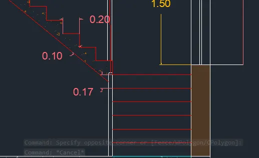
- 0.2m lintel thickness is shown on top of every wall as lintel is provided throughout.
- From the floor, 0.15m is offseted for the thickness of the slab.
- Draw parapet wall and terrace headroom by using projection.
- This procedure same for first floor.
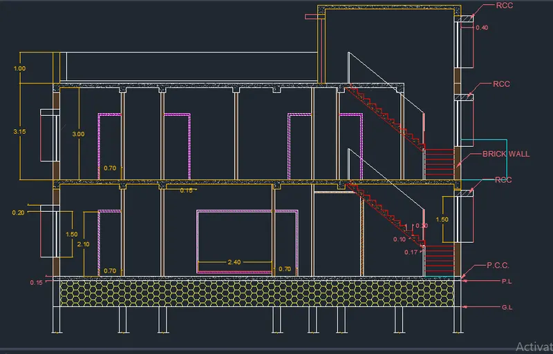
Step :26 Hatching and dimensioning the section
- Hatch the brick wall with solid scale 45.
- Hatch the slab thickeness ,lintel beam with AR_CONC for concrete.
- From the plinth level give 0.15m offset fro the P.C.C.
- With multileader insert the text by marking R.C.C , Brickwall, P.C.C etc.
- Give the dimensions.
Use of layout :
Step :25 Creating viewports in layout
- Go to layout , and create a plot .
- First set the page to A3 by clicking on page set up manager.
- Create a viewport by "MV"command (multiview ) , draw 4 viewports by rectangle.
- Command "MS" for model space ,go to model space and adjust the view such a way that the plan , elevation and section is visible .
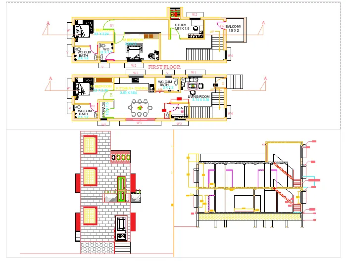
Plot:
Step:26 Plotting the layout
* By plot command ,select layout to be printed, name as dwg. to pdf ( to convert to pdf), pen assignment as monochrome .It can be saved as pdf.
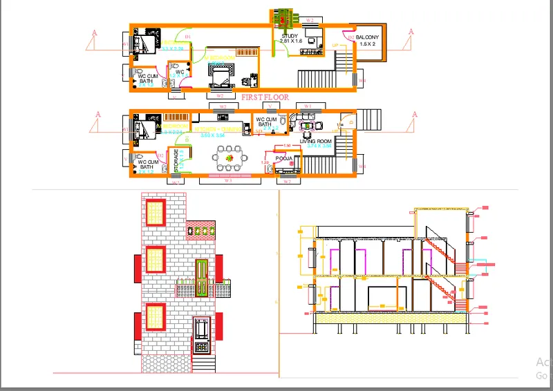
2. Structural drawing:
a. Column plan layout of the building
Step:25 Drawing of section of columns:
- Create columns , by rectangle command 0.23mx0.23m ,place the column in the ground floor plan , in all corners and intersection of walls and place it in layer.
- Copy the same for the first floor
Step:26 Drawing grid lines for columns
- Now draw the centre line for column from the annotate tab -centre line .
- Make it a scale of 0.005.
- Delete all the walls and stair.
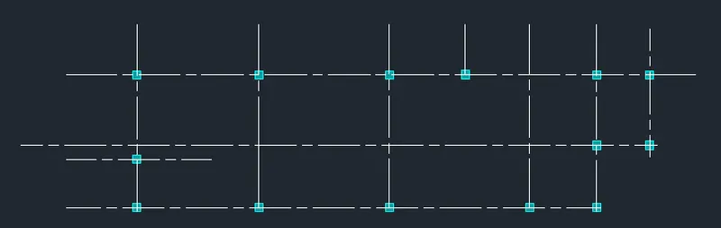
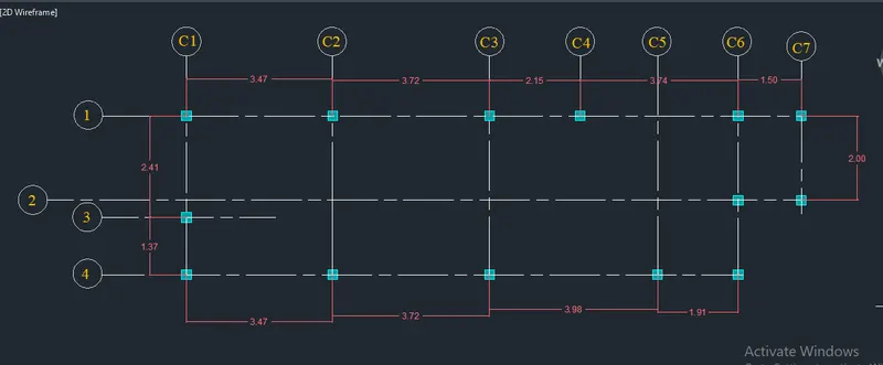
Step:27 Marking of grid lines
- Now mark the grid line as 1,2 in the y direction and C1,C2,.....,C7 in the x direction.
- Create a circle and insert text into it for he marking.
- Dimension between the grid lines are mentioned as it is used for marking the columns.
b. Beam plan layout of the building:
i.Plinth beam layout
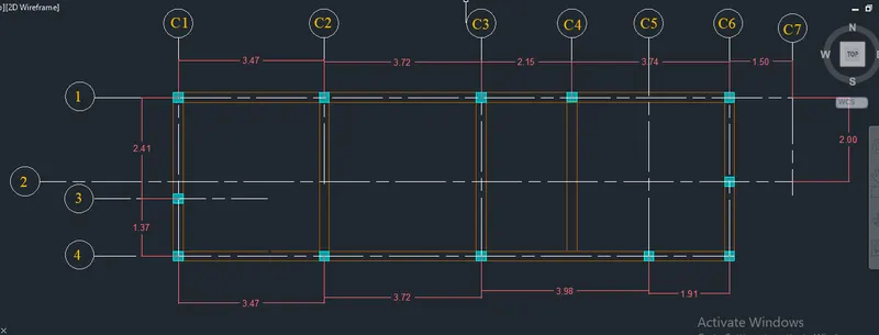
Step:28 Drawing of plinth beam- primary beams
- To draw plinth beam layout, copy the ground floor plan with column .
- Plinth beam is provided below all the walls.
- Primary beam are beams provided from one column to other.
- Secondary beams are beams connected from the primary beams.
- Create a layer for beam .
- First connect the columns by beam of width 0.23m , as the wall thickness is 0.23m, these are the primary beams.
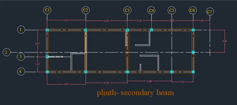
Step:29 Drawing of plinth- secondary beam
- Now connect the other internal walls as beams of width 0.1m , beam to beam connections are secondary beams.
- Delete all the walls.
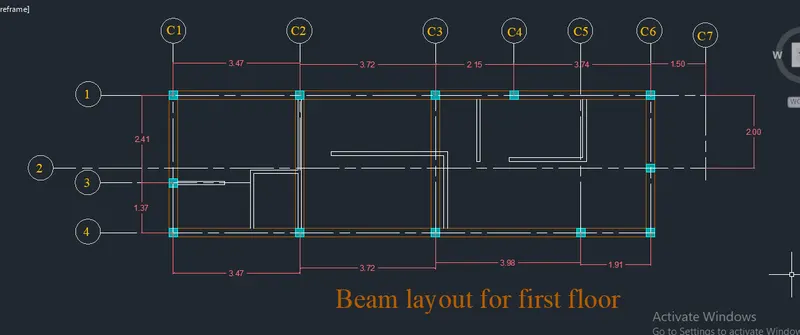
ii. Beam layout for first floor
Step:30 Drawing of primary beams of top floor.
- Copy the first floor plan with column drawn.
- Draw beam of width 0.23m connecting all the columns
- Here for staircase, a beam is drawn at the landing slab level of top floor.
c. Footing plan layout of the building:
Step:35 Drawing of footing
- Steped footing of size 1.2m x1.2m is provided.
- Create a rectangle with dimension 1.2x1.2 m , Give offset 0.1,0.15, and 0.25 inside of rectangle after that place the centre of rectangle with the centre of column.
- make a section of footing give rise of steps are 0.2 and pcc thickness is 0.1.
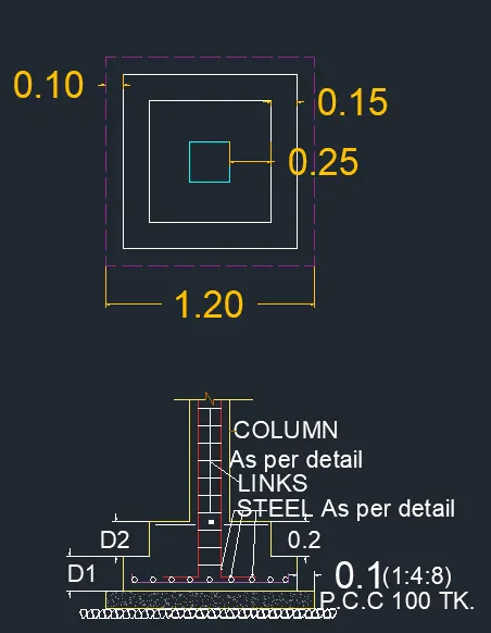
- Place the foooting at required place.
- Make a layer for footing and place the footings in that layer.
- Dimension the distance between footing and column.
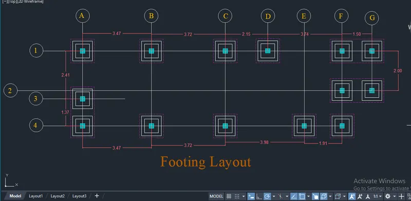
Step:36 Creating layout and plot for structural drawing
- Create layout as structural and make viewports and place the drawings
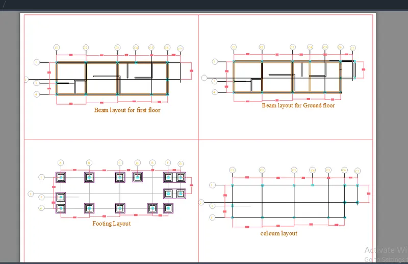
- Plot the darwing to pdf by pen assignmnet as monochrome

Result: Architectural and structural plan of a two storeyed residential building is drawn.
1. Architectural plan is drawn:
a. Plan of two storeyed residential building is drawn.
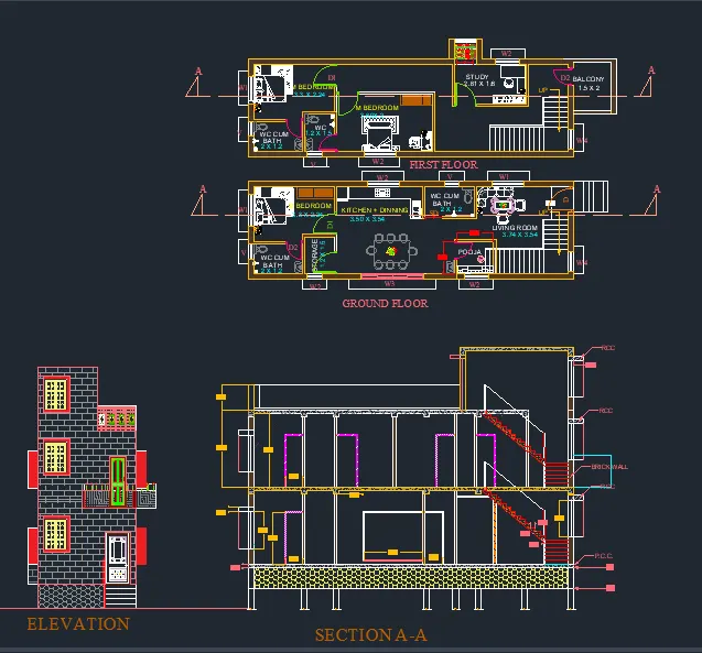
Plot :
i. Ground floor plan of residential building
ii. First floor plan of residential building
c. Section of the building
d. Elevation:
2. Structural plan has been drawn:
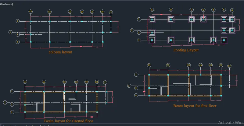
a. Column layout :
b. Beam layout is drawn:
i. Plinth beam layout is drawn
ii. Beam for first floor is drawn
c. Footing layout is drawn