Creating Bar Bending schedule, Different Door types, and Creation of standard drawing templates using AutoCad
- Creating the templates
Aim:
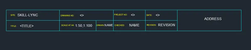
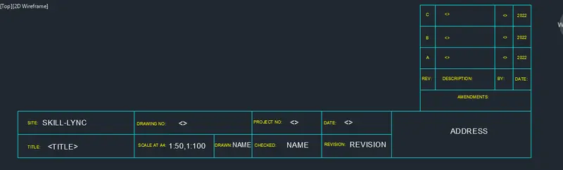
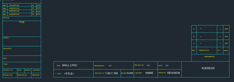
To create the custom1_ titleblock and custom2_ titleblock template using AutoCAD.
Introduction:
In this project we have to create a template of custom1_ titleblock and custom2_ titleblock using various tools .The template is arranged in the table format that specifies the drawing and which has provided in the corner of the drawing sheet.
Command used:
- Units
- Limit
- Line
- Rectangle
- Offset
- Trim
- Move
- Mtext
- Block definition
- Block insert
- Attribute
Procedure:
- Open the AutoCAD application and type Qnew to open new drawing
- Type unset unit set decimal and precision as 0.0
- Select the unit as millimetre in the insertion scale
- Type the limit in the command box and set the lower limit as 0 ,0 and upper limit as 10000,10000
- Type Z and A for zoom and zoom all
Step1:(Custom 1_titleblock)
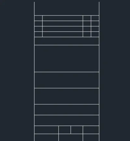
- Select the rectangle in the command box and draw a rectangle of size 2400 ,5200 and explode it
- Select the offset tools and select the offset distance as 500 and offset the top of the line through inside
- Give the offset distance again as 200 and offset top of the line through inside for 4 times
- Repeat the offset command and give offset distance as 300,1000,600,600,400,400,300 respectively
- Select the trip tool by typing trim in the command box and trim unnecessary line
- Select the offset tool and give offset distance as 300,1500,300,300 respectively and select the left line and offset it through inside as shown in figure
Step 2:
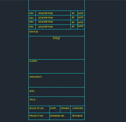
- Select textiles standard and fort size and give the text height as per requirement
- Select the multilant text and type text as rev, description, by and date
- Select the copy command and select the m text command and paste it through desired location
- Using multi line text again and type text as status client, architect site scale at a project number, date wrong number, drone, checked, revision respectively
- Place the text into desire location by using move command
- Use the layer property and give coloureto the block and the text
Step 3:
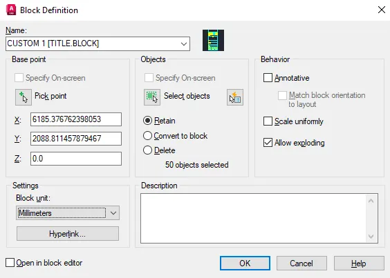
- Using block definition dialogue box by typing b give the name of the box as custom1_title block
- Select the pic point in the block definition and pick the point in the sketch template
- Select the object as whole table template and press entre
- Open the insert block by typing I and insert the custom1_title block into the screen
Step 4:(Custom2_title block)
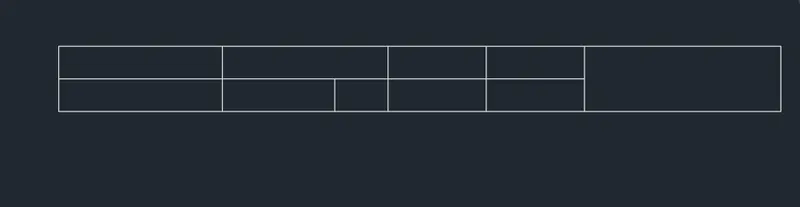
- Select the rectangle in the command box and draw a rectangle of size 1000,12000 and explode it
- Select the offset tools and select the offset distance as 500 and offset the top of the line through inside
- Repeat the offset command and give offset distance as 2500,2532,1500,1500,3000 respectively
- Select the left line and offset it through inside
- Select the trip tool by typing trim in the command box and trim unnecessary line
Step 5:
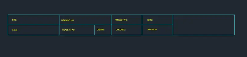
- Select the textile as standard and give the text height as per requirement
- Select the multi line text and type the text as site, title, drawing number, scale at A4 , drawn, project number , checked,date,and revision
Step 6:
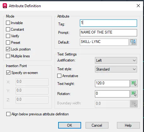
- Open the attribute definition and give tag as 1
- Give the promote as the Name of the site
- Give the default as site
- Give the log position option and insert point as specified on the screen
- Specify the location where we want to insert the attribute text
Step 7:
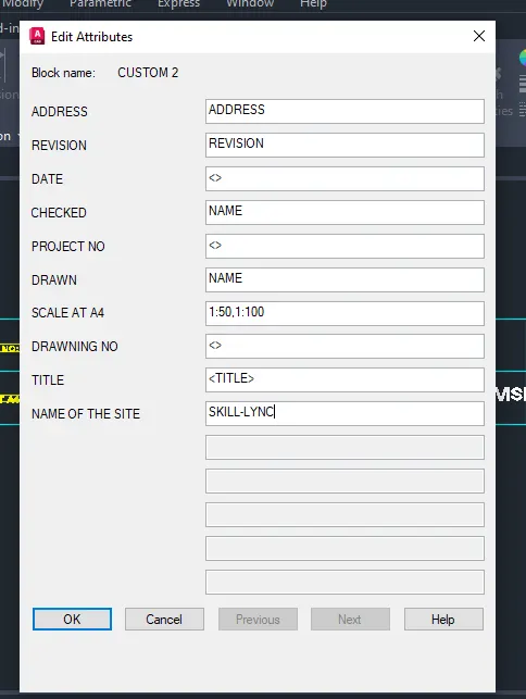
- Similarly do the same process for all the attributes
Step 8:
- Draw the table below the previous table as shown in figure
- Now select the M-text command and Move it to the location
- Select the text and paste it through the desire locations
Step 9:
- Open the block definition block and give the name of the block as custom2_titleblock
- Select the pic point in the block definition and pick the point in the sketch template
- Select the object as whole table template and press entre
- Open the insert block by typing I and insert the custom2_title block into the screen
Result:
- Creating door panels for wardrobe
Aim:
To create door types D1 and D2 for the warehouse using AutoCAD
Introduction:
In the project we create two sides of the door type for the warehouse and has been drafted with the names using various tool in the AutoCAD
Command used:
- Units
- Limit
- Rectangle
- Offset
- Divide
- Line
- Mirror
- Copy
- Block definition
- Block insert
- Dim linear
- Mtext
Procedure:
- Open the AutoCAD application and type Qnew to open new drawing
- Type unset unit set decimal and precision as 0.0
- Select the unit as millimetre in the insertion scale
- Type the limit in the command box and set the lower limit as 0 ,0 and upper limit as 10000,10000
- Type Z and A for zoom and zoom all
Step 1:(Door 1)
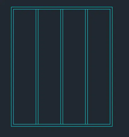
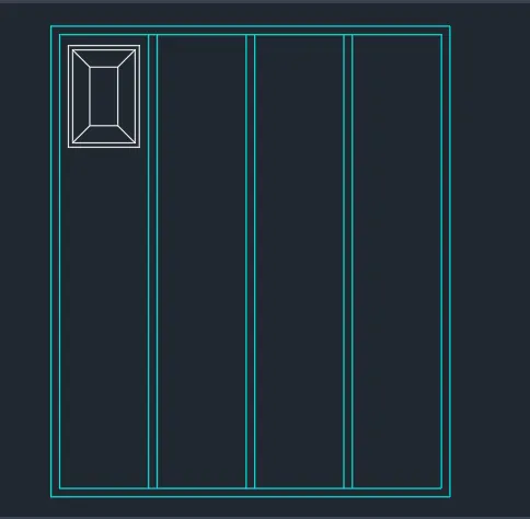
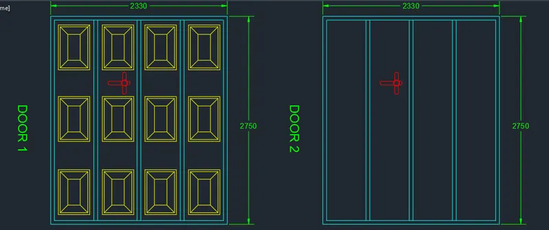
- Select the rectangle tool and raw rectangle of size 2330 X 3750 mm
- Select the offset tool by typing of set in the command box and give upset distance as 50 mm and offset it through inside
- Select the divide tool by typing d i v and divide the top line into 4 segments and draw vertical lines from it
- Select the offset tool and give offset distance as 25 mm
- Offset divided line on both side for thickness and delete the centre line
- Select the layer command and give the layer property
Step 2:
- Select rectangle tool and draw rectangle as shown in the panel and inserted in the door as shown in figure
- Select the offset tool and offset distance as 25 mm and 100 mm through inside
- Draw the line joining the corners of the rectangle is shown in figure
Step 3:
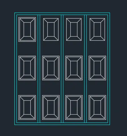
- Select the mirror tool by typing mirror and select the panel and mirror it through the both sides
- Select the copy tool and select the peneline copy it through the desire location as shown in figure
Step 4:
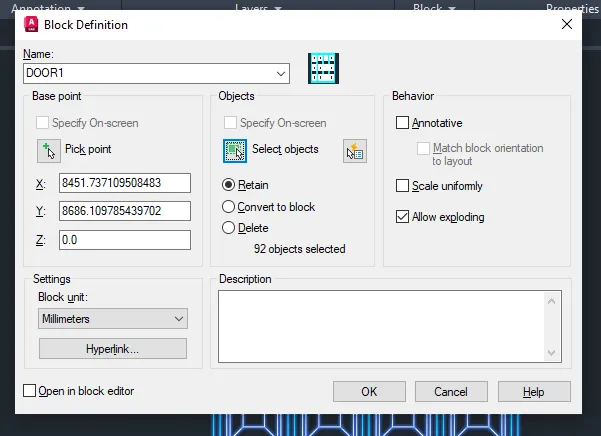
- Open the block definition and give the door name as Door 1
- Select the pic point in the block definition and pick the point in the door and select the object as the whole door
- Click allow exploding and select retain option and press okay to convert it into a block as shown in figure
Step 5:
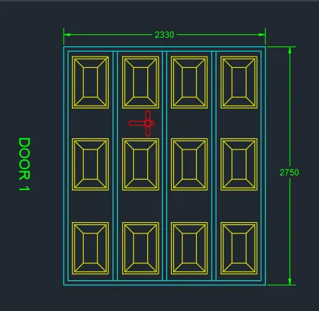
- Open the insert block by typing I and insert the door into the screen
- Select the dimension by typing dimension command and specify the dimension of the door as per the drawing
- Select multi text and type the door text as Door 1 shown in figure
Step 6:(Door 2)
- Select the rectangle tool and raw rectangle of size 2330 X 3750 mm
- Select the offset tool by typing of set in the command box and give upset distance as 50 mm and offset it through inside
- Select the divide tool by typing d i v and divide the top line into 4 segments and draw vertical lines from it
- Select the offset tool and give offset distance as 25 mm
- Offset divided line on both side for thickness and delete the centre line
- Select the layer command and give the layer property
Step 7:
- Select direct angle tool and draw two rectangle perpendicular to each other
- Placr it in order to show the lock position
- Open the block definition and give the door name as Door 2
- Select the pic point in the block definition and pick the point in the door and select the object as the whole door
- Click allow exploding and select retain option and press okay to convert it into a block as shown in figure
- Select the dimensions as per the drawing and select multi line text and type text as Door 2

Result:
- Creating electrical symbols
Aim:
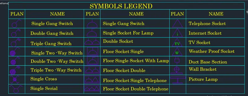
Create electrical symbols as a block and insert them into a table using AutoCAD
Introduction:
In this project we create different type of electrical symbols and the legend has been created with the blocks of the symbols along with the table insertion
Command used:
- Circle
- Line
- Rectangle
- Hatch
- Mirror
- Copy
- Mtext
- Block definition
- Block insert
- Field
Procedure:
- Open the AutoCAD application and type Qnew to open new drawing
- Type unset unit set Decimal and precision as 0.0
- Select the unit as millimetre in the insertion scale
- Type the limit in the command box and set the lower limit as 0 ,0 and upper limit as 10000,10000
- Type Z and A for zoom and zoom all
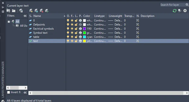 Select the layer command and define layer properties
Step 1:(Single gang switch)
- Select the circuit tool and draw a circle of radius 100 mm
- Select the line tool by typing line command
- Draw a vertical line incline through the circle and draw a whose on to line perpendicular to the previous line as shown in figure

Step 2:(Double gang switch)
- Select the circle tool by typing see and draw a circle of radius 100 mm
- Draw a line by using line command
- Draw vertical line in client through the circle and draw two horizontal lines perpendicular the previous line as shown in figure

Step 3:(Triple gang switch)
- Select the circle tool by typing see and draw a circle of radius 100 mm
- Draw a line by using line command
- Draw vertical line in client through the circle and draw three horizontal lines perpendicular the previous line as shown in figure

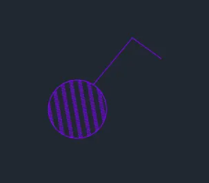
Step4:(Single two way switch)
- Select the circle tool by typing see and draw a circle of radius 100 mm
- Draw a line by using line command
- Draw vertical line in client through the circle and draw horizontal lines perpendicular the previous line as shown in figure
- Select the hatch pattern has solid and pick the point as the circle and field the hatch
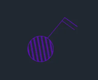
Step 5:(Double two way switch)
- Select the circle tool by typing see and draw a circle of radius 100 mm
- Draw a line by using line command
- Draw vertical line in client through the circle and draw two horizontal lines perpendicular the previous line as shown in figure
- Select the hatch pattern has solid and pick the point as the circle and field the hatch
Step 6:(Triple two way switch)
- Select the circle tool by typing see and draw a circle of radius 100 mm
- Draw a line by using line command
- Draw vertical line in client through the circle and draw three horizontal lines perpendicular the previous line as shown in figure
- Select the hatch pattern has solid and pick the point as the circle and field the hatch

Step 7:(Switch cross)
- Select the circle tool by typing see and draw a circle of radius 100 mm
- Draw a line by using line command
- Draw vertical line in client through the circle and draw horizontal lines perpendicular the previous line as shown in figure
- Select the hatch pattern has solid and pick the point as the circle and field the hatch
- Select the mirror tool and mirror it through the top and the bottom as shown in figure

Step 8:(Switch serial)
- Select the circle tool by typing see and draw a circle of radius 100 mm
- Draw a line by using line command
- Draw vertical line in client through the circle and draw horizontal lines perpendicular the previous line as shown in figure
- Select the mirror tool and mirror it through the left side as shown in figure

Step 9:(Single socket)
- Select the circle tool by typing see and draw a circle of radius 100 mm
- Draw a line of 10 mm at the top as shown in figure
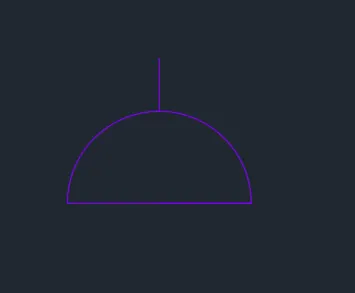
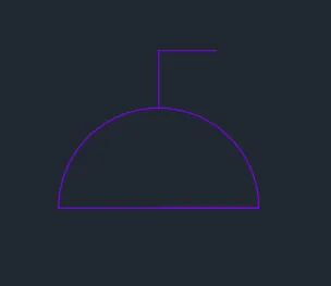
Step 10:(Single socket for lamp)
- Select the circle tool by typing see and draw a circle of radius 100 mm
- Draw a line of 10 mm at the top andro the another line perpendicular to the previous line as shown in figure
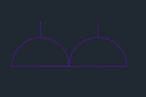
Step 11:(Double socket)
- Select the circle tool by typing see and draw a circle of radius 100 mm
- Draw a line of 10 mm at the top as shown in figure
- Select the copied tool and copy it to create the same and place it using snap on
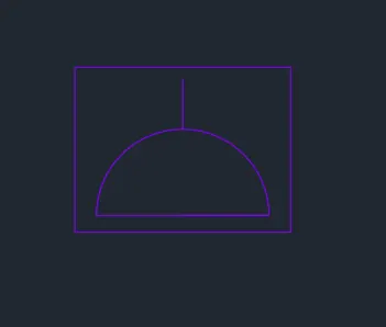
Step 12:(Floor socket single)
- Select the circle tool by typing see and draw a circle of radius 100 mm
- Draw a line of 10 mm at the top as shown in figure
- Draw a rectangle surrounding the single socket
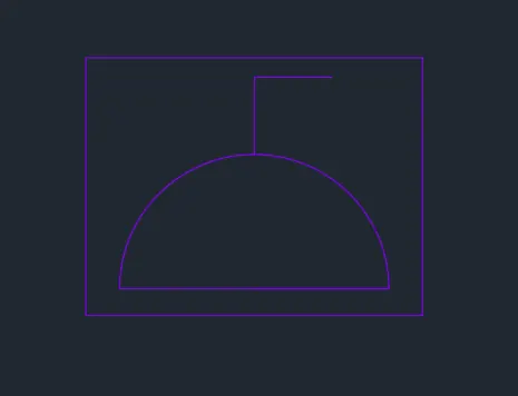
Step 13:(Floor socket single for lamp)
- Select the circle tool by typing see and draw a circle of radius 100 mm
- Draw a line of 10 mm at the top and draw another perpendicular line to the previous line as shown in figure
- Draw a rectangle surrounding the single socket
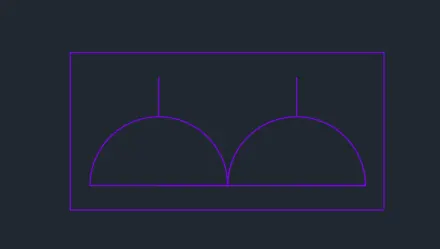
Step 14:(Floor socket double)
- Select the circle tool by typing see and draw a circle of radius 100 mm
- Draw a line of 10 mm at the top as shown in figure
- Select the copy tool and copy it to create the same and place it using snap on
- Draw a Rectangle surrounding the double socket
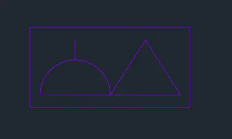
Step 15:(Floor socket single telephone)
- Select the circle tool by typing see and draw a circle of radius 100 mm
- Draw a line of 10 mm at the top as shown in figure
- Create a triangle beside the sides socket as shown in figure
- Draw a rectangle surrounding to it
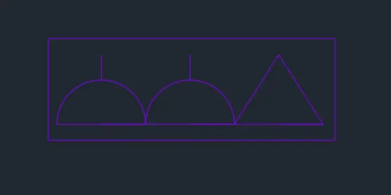
Step 16:(Floor socket double telephone)
- Select the circle tool by typing see and draw a circle of radius 100 mm
- Draw a line of 10 mm at the top as shown in figure
- Copy select the copy tool and copy it to create the same and place it using snap on
- Creative triangle beside the double socket as shown in the figure
- Draw a rectangle surrounding to it
Step 17:(Telephone socket)
- Select the line tool and draw triangle by using line tool

Step 18:(Internet socket)
- Select the line tool and draw triangle by using line tool
- Insert text"i' in the triangle

Step 19:(TV socket)
- Select the line tool and draw triangle by using line tool
- Insert text"TV' in the triangle

Step 20:(Weatherproof socket)
- Select the line tool and draw triangle by using line tool
- Insert text"W'' in the triangle

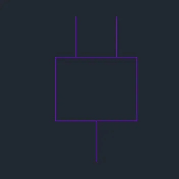
Step 21:(Duct base section)
- Draw a rectangle by using REC command
- Draw a single line below the rectangle and similarly draw two line above the rectangle as shown in figure
Step 22:(Wall Bracket)
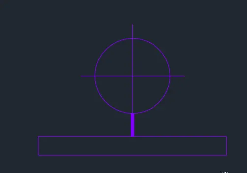
- Draw a rectangle by using REC command
- Draw circle above the rectangle by using circle command
- Draw the line connecting both rectangle and rectangle
Step 23:(Picture lamp)
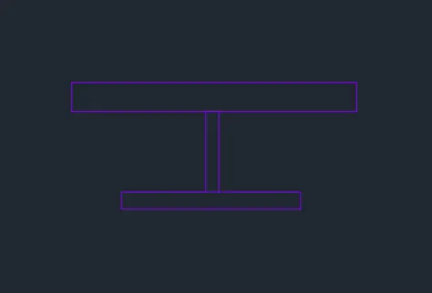
- Draw a rectangle by using REC command
- Draw another small rectangle and place it below the previous rectangle
- Draw the two lines connecting both rectangles
Step 24:
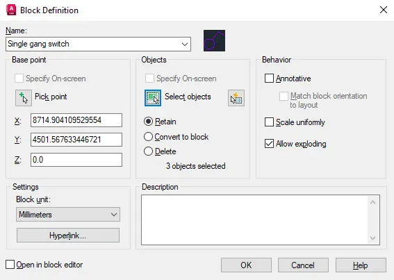
- Open the block definition and give the door name as Single Gang socket
- Select the pic point in the block definition and pick the point in the door and select the object as the whole door
- Click allow exploding and select retain option and press okay to convert it into a block as shown in figure
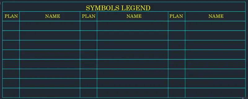
Step 25:
- Draw a rectangle by using REC command
- Select the upset command and do the oxide as per the requirement
- Select the textile standard and slap the text height as per the requirement
- Select multi line text and type the text as symbol legend plan and name respectively
- Slap the copy tool by typing copy in the command box
- Select the text and copy it through the desire location as shown in figure
Step 26:
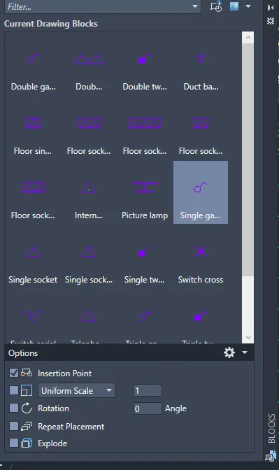
- Open the insert block and type I or insert in demand box
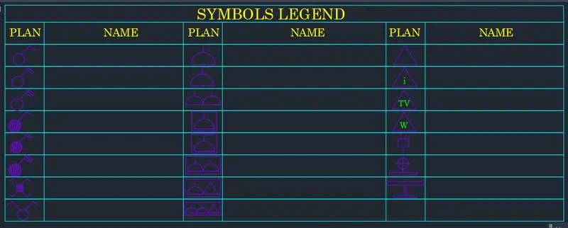
Step 27:
- Select all the symbols into the table at the desired position
Step 28:
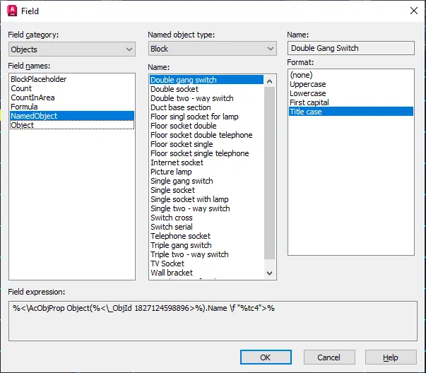
- Open the field dialogue box by typing field in the command box
- Select field category as the object and field name as named object
- Select the name of the object that you want to insert and select the format of the text as per requirement
- Insert it all the desired location similarly do the same process for all the names
Result:
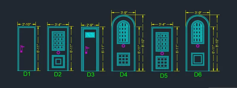
- Creating door types for residential buildings
Aim:
To draw the door types for the digestion building as a block
Introduction:
Door types for the radential building are drawn with the various type of the font elevation design with the various names
Command used:
- Units
- Limits
- Rectangle
- Circle
- Offset
- Trim
- Block definition
- Mtext
Procedure:
- Open the AutoCAD application and type Qnew to open new drawing
- Type unset unit set Architectural and precision as 0.0
- Select the unit inches in the insertion scale
- Type the limit in the command box and set the lower limit as 0 ,0 and upper limit as 100',100'
- Type Z and A for zoom and zoom all
Step 1:(D1)
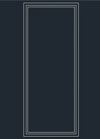
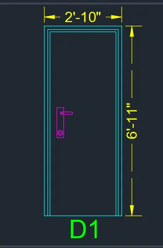
- Select the rectangle command and row rectangle with dimension 2'10" as length and 6'11'as width
- Select the offset tool by typing of set and give offset distance as 1.5" and 1" and offset it through inside
Step 2:
- Select the rectangle tool and draw two rectangle perpendicular to each other and fillet those corner of the rectangle with radius of 0.2"
- Draw the circle of radius 0.1" in the rectangle as shown
- Select the multiline text and type as D1
- Create it as a block and give block name as Door1
Step 3:(D2)
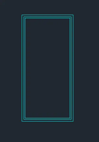
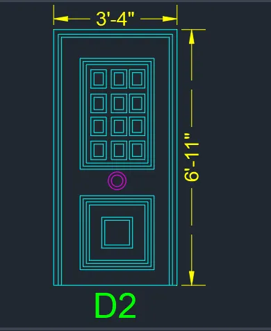
- Select the rectangle command and draw a rectangle with dimension 3'4" as length and 6'11" as width
- Slug the offset tool and give offset distance as 1.5" and 1" and offset it through inside
Step 4:
- Select the rectangle tool and draw a rectangle for the panel with the dimension 2' as length and 3' as width
- Select the offset tool by typing of set and give outside distance as 1" through inside two times
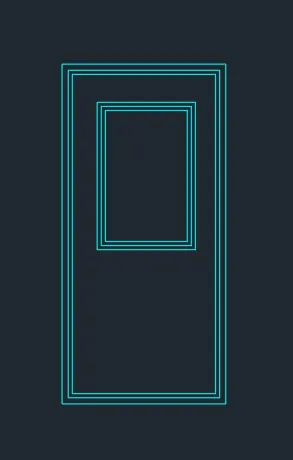
Step 5:
- Select the rectangle command and row rectangle for the panel with the dimensions 6" as length and 10" as width
- Give the offset distance as 1" and offset it inside
- Select the copy tool and copied to desire location as shown in figure
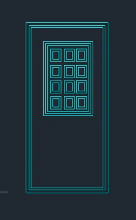
Step 6:
- Slug the rectangle tool and draw a panel with dimension 2' as length and 2'as width
- Offset through inside from the previous line as shown in figure

Step 7:
- Select the circle tool and draw a circle of radius 10" and place it on the middle of the section of the door
- Select the offset tool and offset distance as 1" and objective through inside
- Give the dimensions as per the drawing using the dimension linear
- Create it as a block and give the block name as Door 2
Step 8:(D3)
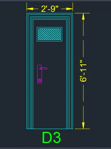
- Select the rectangle tool and draw a panel with dimension 2'9"as length and 6'11"as width
- Select the offset tool and give offset distance as 1",1.5",1",1"
- Offset through inside from the previous line as shown in figure
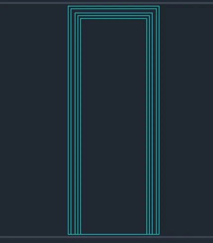
Step 9:
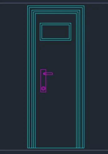
- Select the rectangle tool and draw a panel with dimension 1'6" x 10"
- Select the offset tool and give offset distance as1"
- Offset through inside from the previous line as shown in figure
- Select the circuit tool and draw the circle inside the lock
Step 10:
- Select the hatch tool and do the hatching inside the ventilation
- Give the dimension as per the drawing using the dimlinear command
- Created to the block and give block name as Door 3
Step11:(D4)
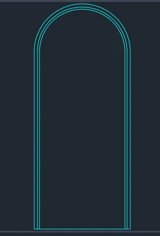
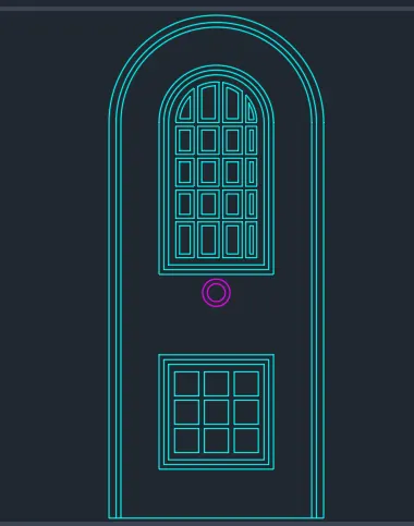
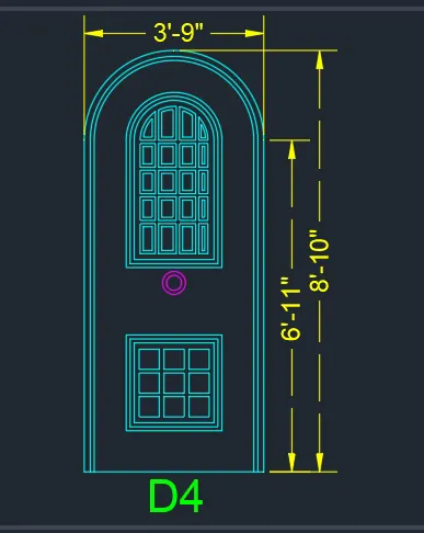
- Select the rectangle tool and row rectangle of dimension 3'9"x 6'11"
- Select the arc tool and are connected both end points
- Select the offset command and give offset distance of 1.5" and 1" respectively an offset the line through inside as shown in figure
Step 12:
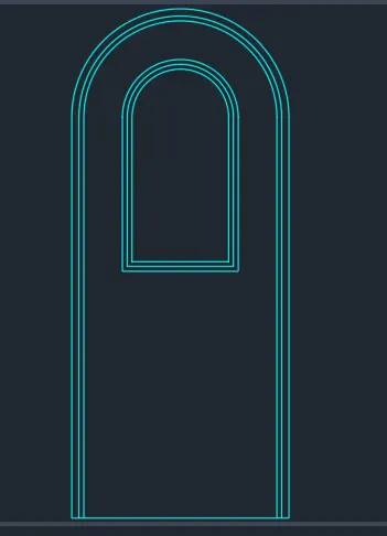
- Select the offset tool and give offset distance as 8"
- Offset the previous arc line through inside
- Select the preview are cline and offset it through inside two times as shown
- Similarly draw another rectangle of 2' x2'
- Offset the distance as 1"
- Offset the rectange two times as shown the thickness
Step 13:
- Slug the rectangle tool and over rectangle 8 "x8"
- Select the offset tool and give offset distanceas 0.8"
- Offset de rectangle inside and select the copy tool and copy the panel to the desire location as shown in figure
- Similarly do the same process for another panel shown below
- Select the circle tool by typing C and draw a colour shown
Step 14:
- Give the dimension as per the drawing requirement
- Create it as a block and give the block name as Door 4
Step15:(D5)
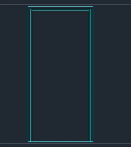
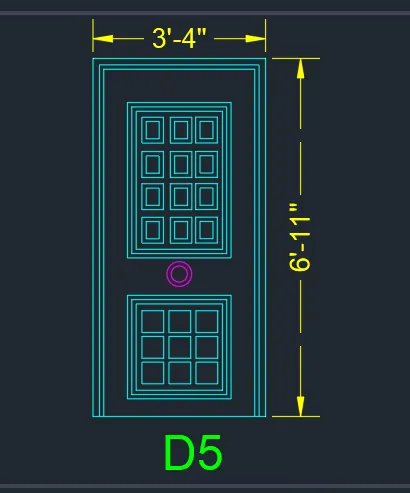
- Select the rectangle tool and row rectangle of dimension 3'4"x 6'11"
- Select the arc tool and are connected both end points
- Select the offset command and give offset distance of 1.5" and 1" respectively an offset the line through inside as shown in figure
Step 16:
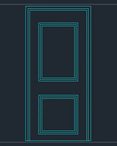
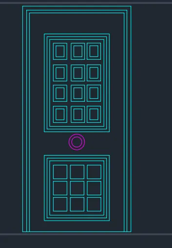
- Select the rectangle tool and draw a panel with dimension 2' x 3'
- Select the offset tool and give offset distance as1"
- Offset through inside from the previous line as shown in figure
- Again Select the rectangle tool and draw a panel with dimension 2' x 2'
- Select the offset tool and give offset distance as1"
- Offset through inside from the previous line as shown in figure
Step 17:
- Select the rectangle tool and draw a panel with dimension 8" x 8"
- Select the offset tool and give offset distance as 0.8"
- Offset through inside from the previous line as shown in figure
Step18:
- Select the Circle tool and draw a circle with a radius of 10" and place it on the middle section of the door
- Select the Offset tool and give offset distance as 1"and Offset it through inside as shown in the figure below
- Give dimensions as per drawing using the DimLinear command
- Select Multiline Text and type text as D5
- Create it as a Block and give the block name as Door 5
Step19:(D6)
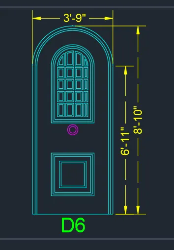
- Select the rectangle tool and row rectangle of dimension 3'9"x 6'11"
- Select the arc tool and are connected both end points
- Select the offset command and give offset distance of 1.5" and 1" respectively an offset the line through inside as shown in figure
Step20:
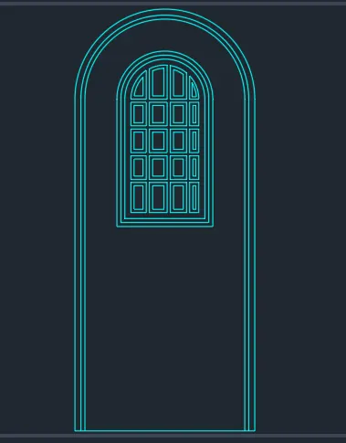
- Select the offset tool and give offset distance as 8"
- Offset the previous arc line through inside
- Select the offset tool again and give offset distance as 1"
- Select the preview are line and offset it through inside two times as shown
Step21:
- Select the rectangle tool and row rectangle of dimension 8"x8"
- Select the offset command and give offset distance of 0.8"
- Offset de rectangle inside and select the copy tool and copy the panel to the desire location as shown in figure
Step22:
- Select the rectangle tool and draw a panel with dimension 2' x 2'
- Select the offset tool and give offset distance as1"
- Offset through inside from the previous line as shown in figure
- Again Select the rectangle tool and draw a panel with dimension 2.5" x 3"
- Offset through inside from the previous line as shown in figure
- Select the circle tool by typing C and draw a circle as shown
Step 23:
- Give the dimension as per the drawing requirement
- Create it as a block and give the block name as Door 6
Result:
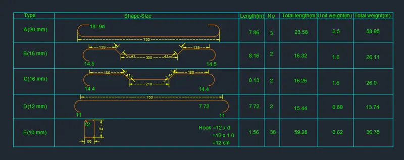
- Creating a bar bending schedule
Aim:
Creating a bar bending schedule and insert the block
Introduction:
The shapes of the steel rebar are created and converted into the blocks and attached to the table which was created bar bending schedule with rebar properties
Command used:
- Line
- Units
- Limits
- Arc
- Rectangle
- Block definition
- Block insert
- Mtext
Procedure:
- Open the AutoCAD application and type Qnew to open new drawing
- Type unset unit set Decimal and precision as 0.0
- Select the unit as millimetre in the insertion scale
- Type the limit in the command box and set the lower limit as 0 ,0 and upper limit as 10000,10000
- Type Z and A for zoom and zoom all
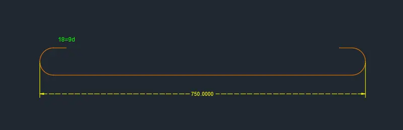
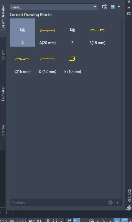
Step 1:(A_20mm)
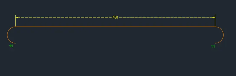
- Select the line command and raw a line of length 750 mm for a straight bar
- Select the arc tool and create an Arc to bend towards the award at both corners
- Create it as a block and give the block name as A_20mm
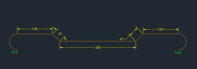
Step 2:(B-16mm)
- Select the line tool and royal line of 300 mm for the straight power
- Draw and incline vertical line of 41 mm on the both edges at an angle of 45 degree
- Draw and extended horizontal line on both side of the length as 139 mm create it as a block and give the block name as B-16mm
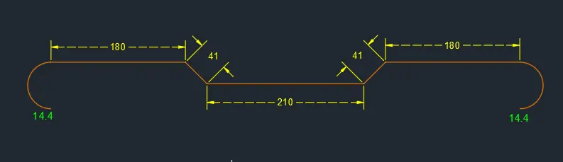
Step 3:(C-16 mm)
- Select the line tool and line of length 210 mm for the straight bar
- Draw an incline vertical line of 41 mm on the both edges at angle of 45 degree
- Draw an extended horizontal line on both side of length of 180 mm
- Draw an Arc in the downward direction on the both corners
- Create a block and give theblock name as C-16 mm
Step 4:(D-12mm)
- Select the line command by typing line in the command box and draw line of length 750 mm for the straight bar
- Select the arc tool and create an Arc bent downwards at the both corners
- Create it as a block and give the block name as D-12mm
Step 5:(E-10mm)
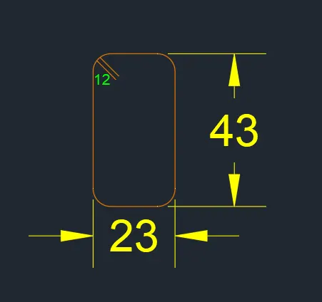
- Select the rectangle tool androe rectangle of dimension 23 x 43
- Select the select tool and fillet the corners with the radius of 15 mm
- Draw two lines in client of the length 120 mm at the left corner as shown in figure
- Create it as a block and give the block name as E-10mm
Step 6:
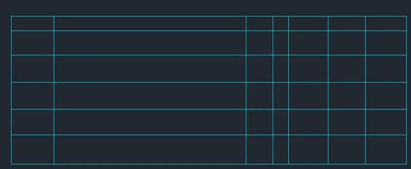
- Select the rectangle tool and draw a rectangle as shown to create a table
- Select the offset tool and offset the line according to the positions
Step 7:
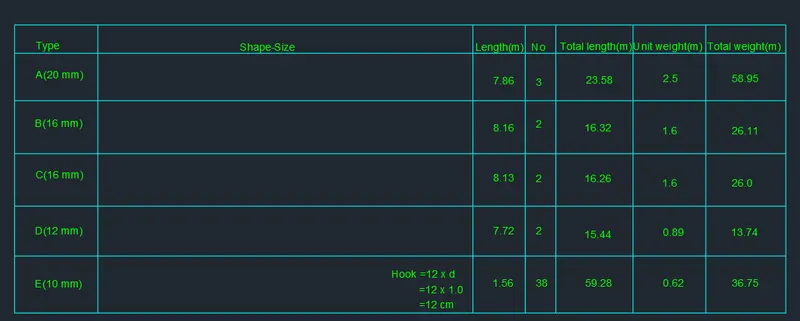
- Select multi line text and type text as per the drawing
- Select the move tool by typing m and select the text and move it to through the desire location as shown in figure
- Select the copy command and select the text and paste it through the desire location
Step 8:
- Open the insert block and insert all the bars into the screen as shown in figure
Result: