Project 1 _Creating an Architectural plan for the provided plot size and develop relevant basic structural drawings
AIM
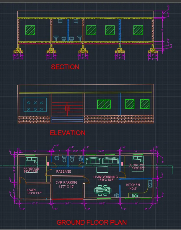
to draw the following plan, elevation and section.
INTRODUCTION
This plan elevation and section are created using autocad and the procedure is explained in detail in each steps and the commands are used in this drawing are.
COMMANDS USED IN THIS DRAWING
- L- LINE
- F8- ORTHO MODE
- GRIDMODE
- F10 - POLAR TRACKING
- ST - STYLE TEXT
- DT-SINGLE TEXT
- T- MULTITEXT
- C- CIRCLE
- CO-COPY
- M-MOVE
- T- TEXT
- TR- TRIM
- O-OFFSET
- F- FILLET
- D-DIMENSION STYLE
- REC-RECTANGLE
- layon- layers on
- layoff- laeyrs off
- DIMLINEAR
- DIMCONT
- DIMBASE
- LEADER
- QLEADER
- SC-SCALE
- LA-layers
- ADC-design center
- B-Block
- I-insert
- Xl-xline
- H-hatch
PROCEDURE
- open autocad file in windows desktop.
- a dialog box will open it shows startup from scratch.
- click the radio button imperial to start the project.
- in command box type gridmode to show the gridmode by typing 1 in the command box
- type F8 to get ortho on.
- type limmax to set the maximum layout.
- type llmits to set the layout.
- TYPE UN FOR UNITS and set to engineering.
STEP 1
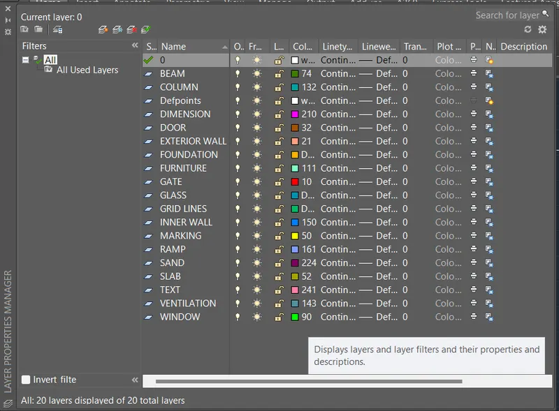
Adding of layers
type LA-layers tab will open.
STEP 2
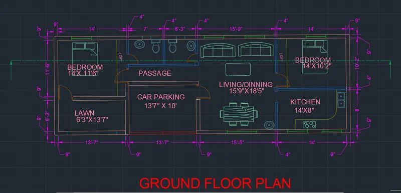
Type L line draw the plan for 60 x 20 feet
draw the outer wall and inner wall.
type O- offset to outer wall and inner wall
type DT- text inside the plan.
type T- multiline text
type D-dimension style to dimension the plan.
type T- multiline text to specify the rooms.
type B- block to draw the door and windows.
type ADC- design center to set the furniture to aligh as per the rooms.
draw the window and door and to complete the plan.
Step 2
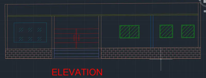
ELEVATION
TYPE xl- xline in the vertical direction to align in the plan.
type H-hatch the plan in the properties.
type LA -layers align as per the layer properties.
type t- multiline text to align as per the text.
STEP 3
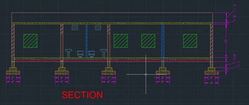
SECTION
TYPE xl- xline in command to align as per the plan.
according to wall,interior wall plumbing as per plan.
type h-hatch the properties as per the section
adding of layers in window, door, foundation and in dimension,text
type ADC-design center to align as per the plan.
STEP 4
(ARCHITECTURAL PLAN)
STEP 5
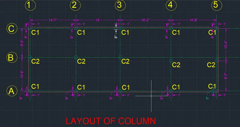
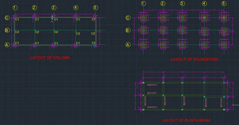
COLUMN POSITION
using of grid lines to mark the center line as per the column as per plan.
marking of column as per design.
placing of column as plan.
after the gridlines are aligned the column are placed as per the plan.
type dimlinear- to dimension the plan corrcetly placed and to easily findout.
STEP 6
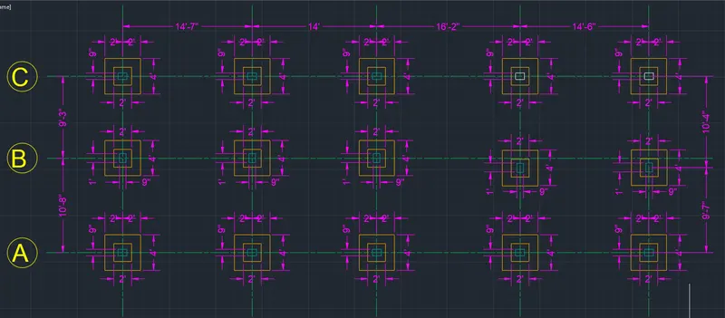
FOOTING PLAN
use the gridlines to mark the center of the column.
as per the column design the footing center lines are marked.
footing size in first step 4'x4'.
footing size in second step 2'x2'
mark the foundation and name it through gridlines.
type dimlinear- to dimension the footing of column and placing through gridlines.
STEP 7
BEAM PLAN
use the gridlines to easily align the beam as per plan.
type l-line to connect the beam each by each to column.
type t- text the beam as various sizes.
type dimlinear- dimension the beam as per plan.
after beam postioning align as per plan mark the beam for various sizes.
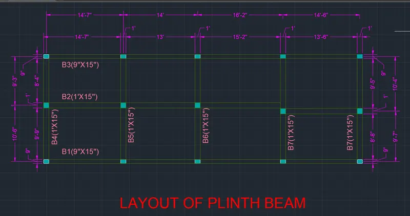
STRUCTUTAL PLAN
RESULT
The follwing plan,elevation and section(architectural drawing)and structural drawing is completed.