Project 1 _Creating an Architectural plan for the provided plot size and develop relevant basic structural drawings
AIM:
Design and draft a layout of residential building with following details
- Plot size : 60’x20’
- Orientation : East facing
- Develop the following:
- Architectural drawing (Floor Plan, Elevations and sections)
- Structural drawing (Column, Beam, Footing plan)
INTRODUCTION:
This is an Architectural plan of Residential building with plot size 60’x20’ in east facing orientation.
The residential building is designed with following:
- Hall,
- Kitchen room,
- Master bedroom,
- Bedroom,
- Attach bathrooms,
- Parking area,
The dimensions of house components are expressed as follows:
WALLS:
- Main wall Thickness is considered as 9”.
- Inner wall thickness is considered as 6”
DOORS:
In this residential building 3 types of varies doors adopted.
- Main door dimension (M.D) is 4’x7’; main door is placed in East direction.
- Both master bedroom and Bed room doors (D1) is 3’-6”x7’.
- Attach bathroom doors (D2) is 2’-6”x7’.
COLUMNS AND BEAMS:
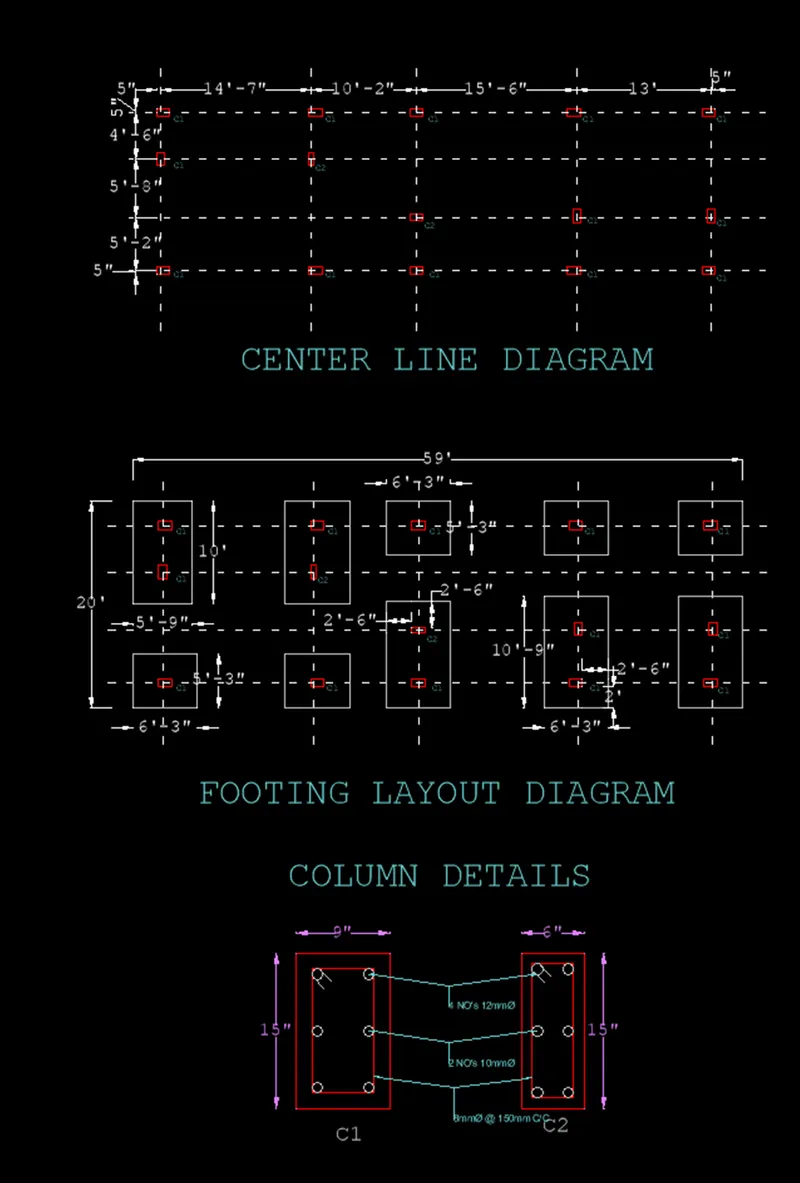
- Here we used columns with dimensions are 9”x15” and 6”x15”.
- Beams are 9”x15” and 6”x15” are used and denoted in the drawing as well.
- Rebar specification of Columns and Beams are explained in the procedure.
WINDOWS AND VENTILATOR:
We used the windows are 4 types and those are W, W-1, W-2 and W-3, also ventilator V-1.
- W = 6’x6’
- W-1 = 5’X5’.
- W-2 = 5’X5’.
- W-3 = 2’X4’.
- V-1 = 2’X1’.
STAIRCASE:
- The staircase consists of 21 steps.
- Thread and Raiser are taken as 1’ and 6” respectively.
- Landing is 3’x5’-6”.
COMPOUND WALL:
- The thickness of compound wall is considered as 6”
- Height of compound wall is taken as 5’.
ARCHITECTURAL DRAWING:
Designing the architectural plan of 60’x20’ size, and orientation is east facing.
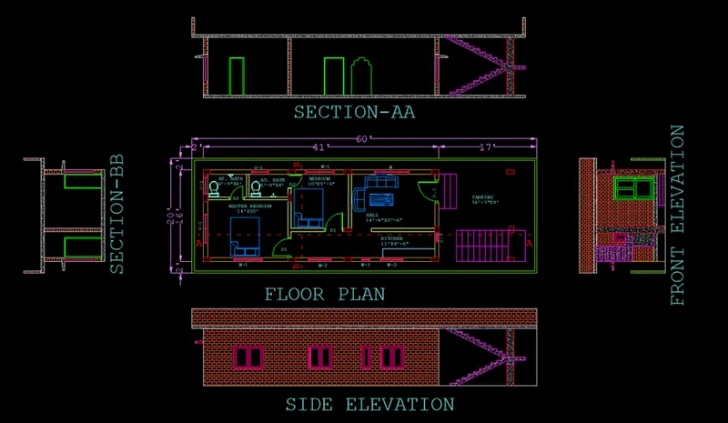
This Architectural plan consists of Floor plan, Elevations and Sections.
- Floor plan:
A scale diagram of a room or suite of rooms viewed from above and used especially for planning effective use and arrangement of furnishings is a floor plan
- Elevations:
Elevation is a type of plan it shows only one side view of house.
1. Sections:
A sectional view or a section looks inside an object. Sections are used to clarify the interior construction of a part that cannot be clearly described by hidden lines in exterior views.
STRUCTURAL DRAWING:
A structural drawing, a type of engineering drawing, is a plan or set of plans and details for how a building or other structure will be built. Structural drawings are generally prepared by registered professional engineers, and based on information provided by architectural drawings.
This structural drawing consists of column layout, beam layout and footing layout.
- Column layout:
Column Layout is a layout mechanism that can work across container boundaries, arranging content on a common grid which consists of a fixed number of columns and a variable number of rows. Embedded UI element containers are merged with their embedding container.
- Beam layout:
Beam layout is very important for any structure. Various things are considered to do a perfect beam layout for a structure. The structural layout plan, often known as the structural scheme of a structure, is critical to its structural performance.
- Footing layout:
Footings stand for structural elements which deliver the loads of column or wall to the elementary soil underneath the structure.
COMMANDS USED:
- Units
- Dimension
- Limits
- Layers
- ADC design centre
- XLine
- Line
- Fillet
- Trim
- Offset
- Block
- Insert
- Rectangle
- Copy
- Move
- Hatch
- Circle
- Mirror
- Rotate
- Scale
- Text
- Leader
- Match property, Etc...
PROCEDURE:
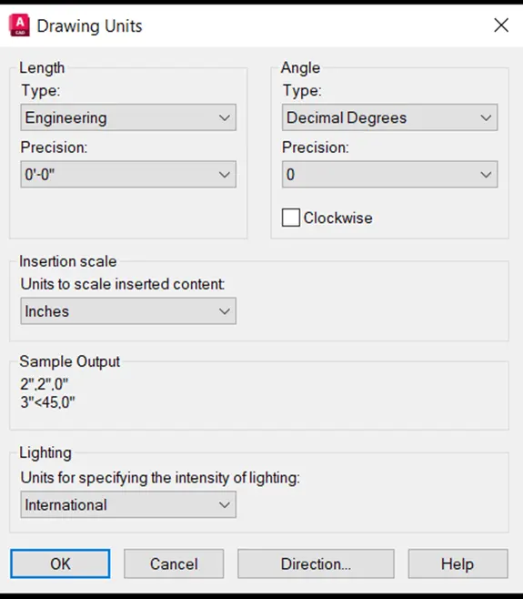
Initially set Units.
- Type UN in command bar then set the units as in below picture.
*CREATING LAYERS:
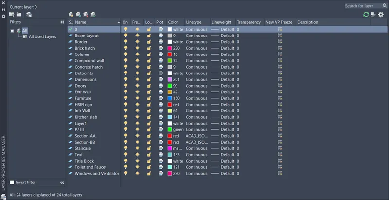
Type LA in command bar then create the layers for residential building drawing.
Layers are created as follows,
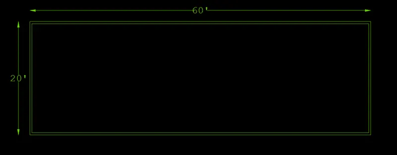
*CREATE PLOT LIMIT:
Choose rectangle command.
- Type REC in command bar then specify the 1st point
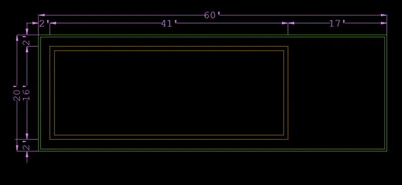
- Mention the plot size 60’x20’ as (@60’, 20’) in command bar.
- Give the dimensions using DIMLIN command.
*CREATING WALLS:
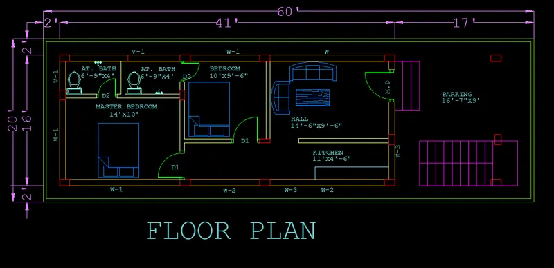
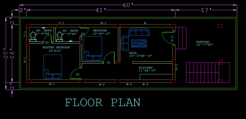
- Create the rectangle with (@41’, 16’) dimension
- Then offset 9” inside the boundary
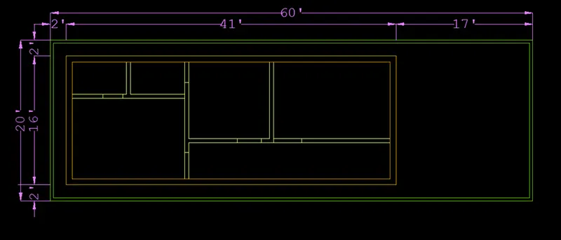
- Create the internal wall using different layer.
- Thickness of internal wall is 6”.
- Dimensions of internal components are as follows;
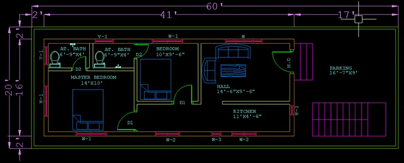
- Master bedroom – 14’x10’
- Attach bathroom 2 no’s – 6’-9”x4’
- Bedroom – 10’x9’-6”
- Hall – 14’x9’-6”
- Kitchen – 11’x4’-6”
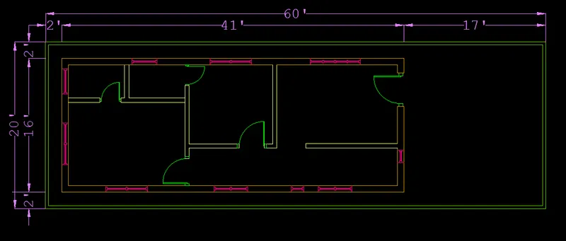
*CREATING DOORS, WINDOWS AND VENTILATOR:
Initially we create Door opening for Hall, Master bedroom, bedroom, Kitchen and Attach bathrooms.
Dimension of doors are as follows:
- Main door (M.D) - 4’x7’
- Bedroom doors (D1) - 3’-6”x7’
- Attach bathroom doors (D2) - 2’-6”x7’
Now we create Window and ventilator openings in Hall, Master bedroom, Bedroom, Kitchen and in Attach bathroom.
- W = 6’x6’
- W-1 = 5’X5’.
- W-2 = 5’X5’.
- W-3 = 2’X4’.
- V-1 = 2’X1’.
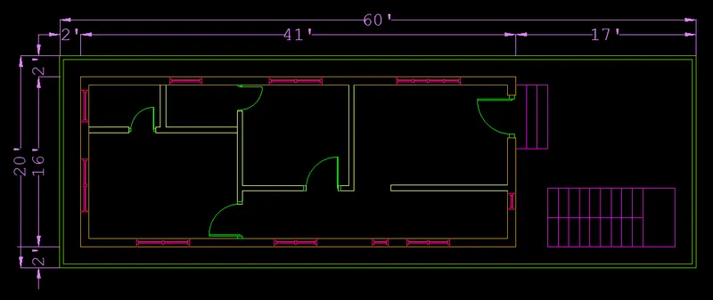
*CREATING STAIRCASE:
Choose layer created for Staircase.
Use Line, array copy, move and etc., commands to create staircase.
- The staircase consists of 21 steps.
- Thread and Raiser are taken as 1’ and 6” respectively.
- Landing is 3’x5’-6”
*PLACING FURNITURE AND PLUMBING TOOLS:
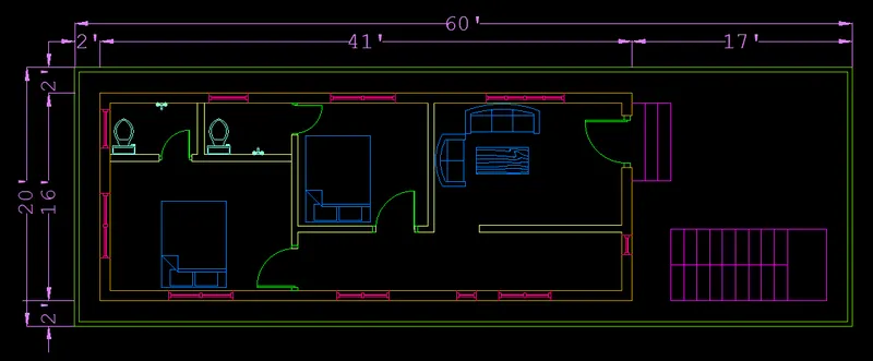
Use ADC tools to insert the furniture, toilet and faucet blocks to place in plan.
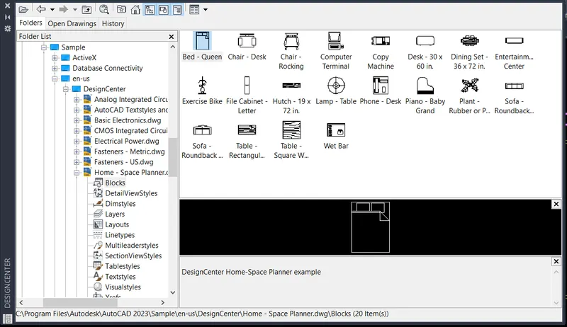
- ADC in command bar search the blocks.
- Move the blocks to screen.
- Set the layers to the blocks.
- Then place in the plan by using move commands.
*MENTIONING THE ROOM DIMENSIONS:
Use Text coomand from ribbon.
- Use layer for Text.
- Specify the text height and angle in command bar.
- Mention the text.
- Copy previos mentioned text and place in necessary room.
- Edit the pasted text as accoring to room.
- Also provide room dimension in same text.
*COLUMN PLACING:
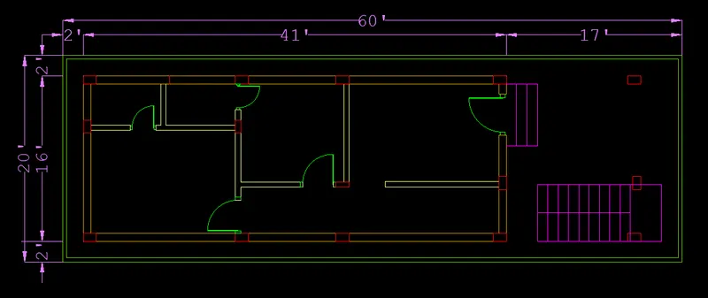
Use Rectangle to create column.
- Column sizes are 9”x15” and 6”x15”.
- Place the column in the plan where columns need to place.
RESULT OF FLOOR PLAN:
*CREATING SECTION FOR FLOOR PLAN:
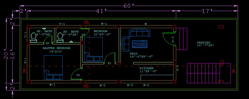
Using ACAD_ISO03W100 line type, create Section-AA and Section-BB line in plan.
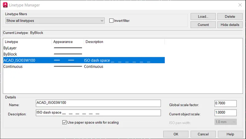
- Use LT command in command bar.
- Load ACAD_ISO03W100 line from Load in box.
- Set global scale factor is 0.7.
- Set the line type as ACAD_ISO03W100 and draw line in Horizontally and vertically in plan
*VIEW OF SECTION-AA:
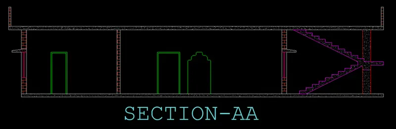
Draw the sections where Section-AA line passes through the components in plan.
- Use Xline command in vertical direction
- Create the projections which we can see in sectional view.
- Draw horizontal line and offset the line according to Floor height is 10’, Slab thickness is 6” and Floor thickness is 6”.
- Offset the window dimension 3’ from bottom of slab.
- Create the window projection 18” from the wall and thickness of window projection is6”.
- Draw the cross section of window in the wall according to window dimension.
- Similarly draw the doors and kitchen opening in the Section-AA.
- Hatch the Slab, walls and floor slab.
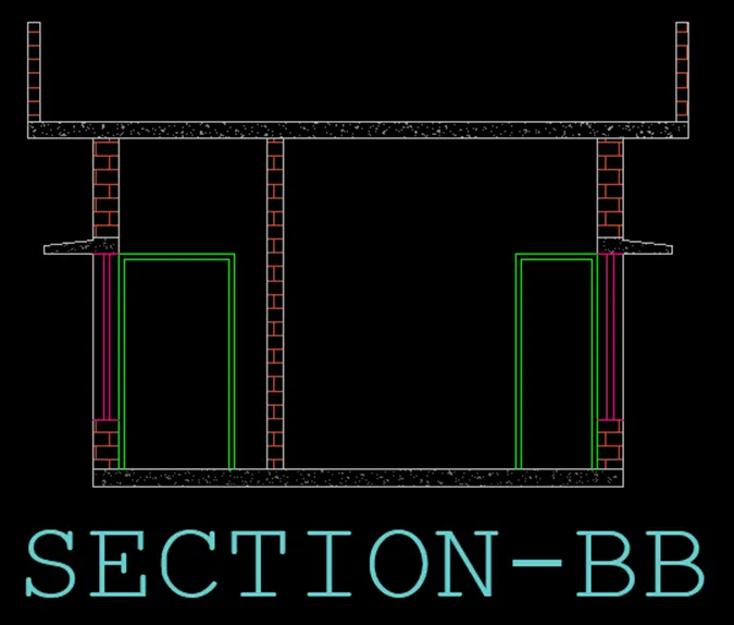
*VIEW OF SECTION - BB:
Draw the sections where Section-AA line passes through the components in plan.
- Use Xline command in horizontal direction
- Create the projections which we can see in sectional view.
- Draw vertical line and offset the line according to Floor height is 10’, Slab thickness is 6” and Floor thickness is 6”.
- Offset the window dimension 3’ from bottom of slab.
- Create the window projection 18” from the wall and thickness of window projection is6”.
- Draw the cross section of window in the wall according to window dimension.
- Similarly draw the doors and kitchen opening in the Section-BB.
- Hatch the Slab, walls and floor slab.
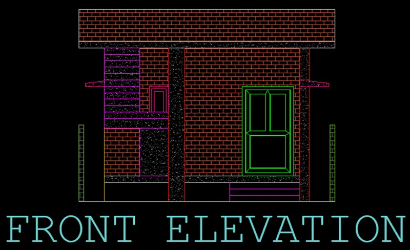
*FRONT ELEVATION:
The side of the house which includes the entrance door, windows, staircase, or front porch.
- Use Xline command extend the projections in horizontal direction.
- In this front elevation, it includes main door, staircase, window, compound wall and window projections.
- Draw vertical line and offset the line according to Floor height is 10’, Slab thickness is 6” and Floor thickness is 6”.
- Offset the window dimension 3’ from bottom of slab.
- Create the window projection 18” from the wall and thickness of window projection is 6”.
- Draw the front view of window in the wall according to window dimension.
- Draw the Main door 4’x7’ size it appears directly.
- Also draw the staircase how it looks from front of the house.
- Also draw the columns, compound wall, parapet wall and steps in front of main door.
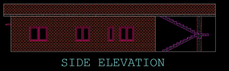
*SIDE ELEVATION:
The side of the house which includes the entrance door, windows, staircase, or front porch.
- Use Xline command extend the projections in vertical direction.
- In this side elevation, it includes staircase, window and window projections.
- Draw vertical line and offset the line according to Floor height is 10’, Slab thickness is 6” and Floor thickness is 6”.
- Offset the window dimension 3’ from bottom of slab.
- Create the window projection 18” from the wall and thickness of window projection is 6”.
- Also create parapet wall and column.
- Hatch the wall surface with Brick hatch, and also hatch slab, staircase, and column with concrete hatch.
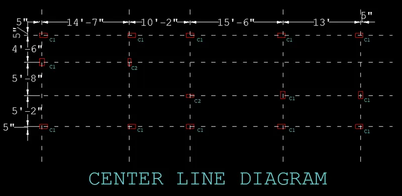
*CENTRE LINE DIAGRAM:
Use ACAD_ISO03W100 line type to draw center line diagram.
- Copy the Columns from Residential plan, paste it.
- Choose the center of the column; extend the line with Xline command in both horizontal and vertical direction.
- Mention the column name as C1 & C2 specified columns.
*FOOTING LAYOUT:
We designed a combine footing where the 2 columns are placed near by distance.
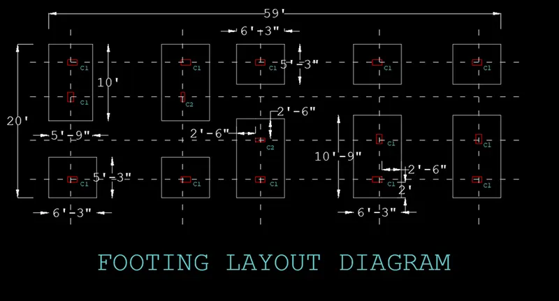
- In diagram we mentioned dimensions for only few footings.
- Dimension of combine footing is 5’-9”x10’.
- Dimension of single footing is 6’-3”x5’-3”.
- Clear distance of footing in horizontal direction is 59’
- Clear distance of footings in vertical direction is 20’.
- Footings are placed within the plot limit.
*COLUMN DETAILS:
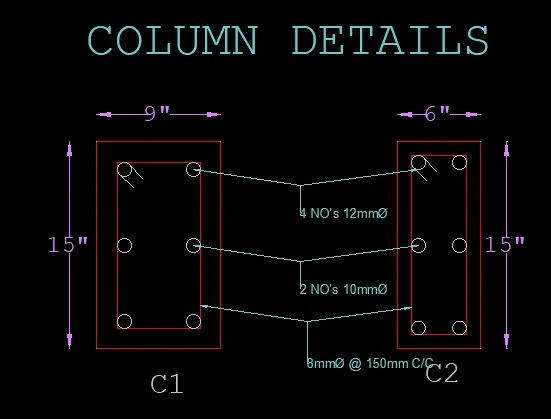
Columns are carries a load from slab and transfer to the footing.
In this plan we used 9”x15” column and 6”x15” column.
- C1 is column-1, in this column 4no’s of 12mm dia and 2 no’s of 10mm dia bars are used.
- C2 is column-2, in this column 4no’s of 12mm dia and 2 no’s of 10mm dia bars are used.
- 8mm dia bars are used for stirrups, 150mm is center to center distance of stirrups.
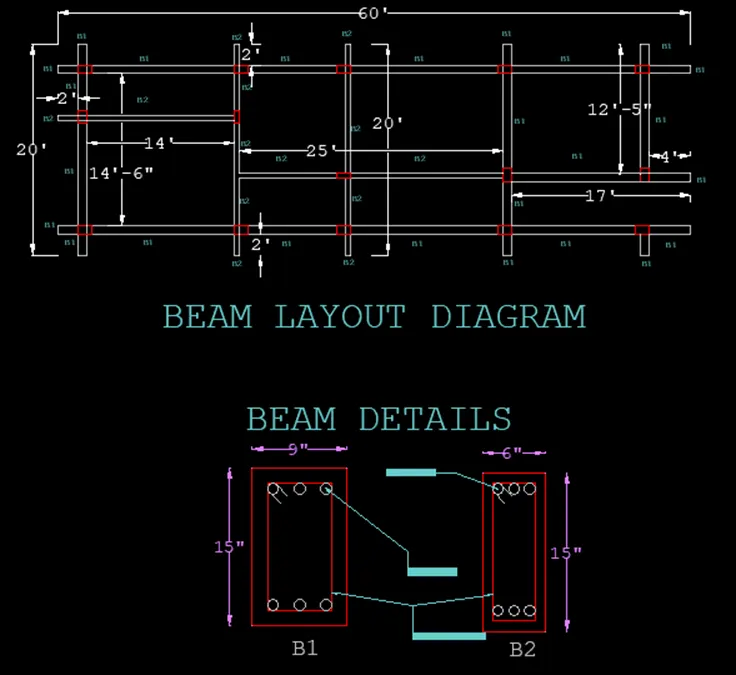
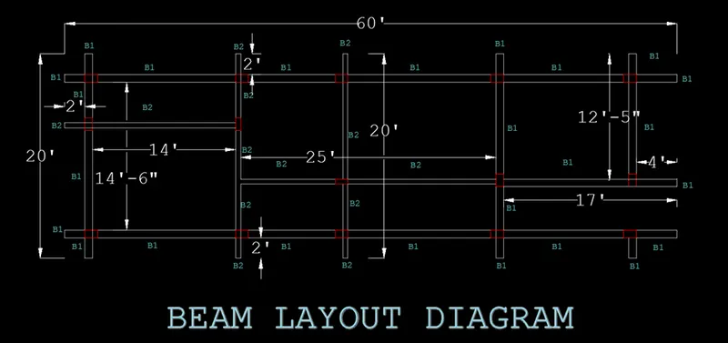
*BEAM LAYOUT:
Beam is a primary element which carries the load from slab to column. And it resists the direct load from slab act as a resisting element in building.
Beam is connects with column and slab.
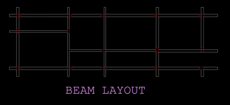
- Beams are B1 and B2 are used in this plan
- B1 – 9”x15” and B2 – 6”x15”.
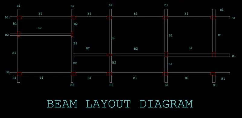
- Clear distance between column and beams are mentioned in the diagram.
- And also projections from column are also mentioned.
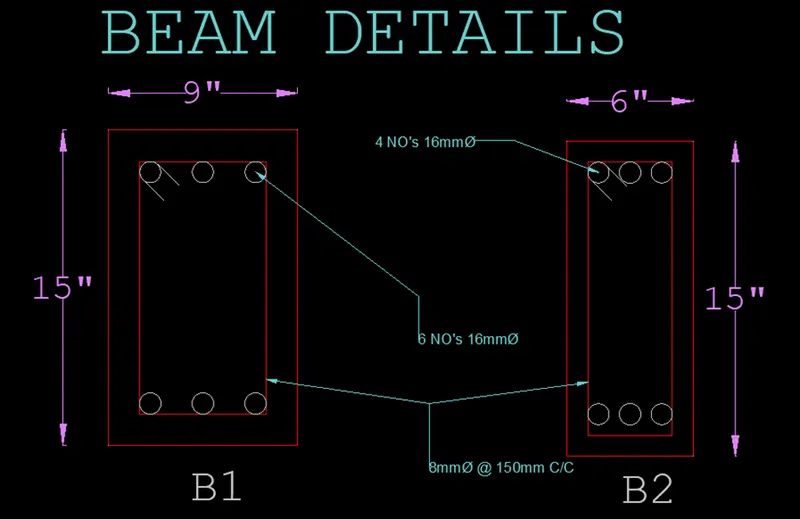
*BEAM DETAILS:
In this plan we used 16mm dia due to resist the dead load from slab.
- B1 and B2 beam are used and dimensions are mentioned in the diagram.
- In both beams we used 16mm dia bars.
- In B1 beam 6 No’s of 16mm dia bars are used.
- In B2 beam 4 No’s of 16mm dia bars are used.
- And also 8mm dia bars are used stirrups.
- And stirrups are placed 150mm center to center distance.
RESULT:
FLOOR PLAN:
PLAN WITH SECTIONS AND ELEVATIONS:
CENTER LINE AND FOOTING LAYOUT:
BEAM LAYOUT: