Creating a Floor plan, Footing detail and Isometric view using AutoCad
Aim:
To creating a Floor plan, Footing details and isometric view using AutoCAD
Introduction:
The main objective of this challenge is to get in touch with various tools in AutoCAD like the rectangle, polylines, modifications tools like copy, move, offset and modes like snap mode and ortho mode. These tools will be understood by creating a footing detail, two bedroom building, cross section of a 2 bedroom building showing foundation details, isometric view of steps and gable wall.
Procedure:
- Set the Units & Dimensions using un & d
- In Units Set the length type and precision.
- In Dimensions set the Lines, Symbols and arrows, Text, Fit, Primary units, Alternative units and Tolerance, then press Set current.
- Now primary setups are completes.
- Question No 01: Cross section of load bearing wall over spread footing.
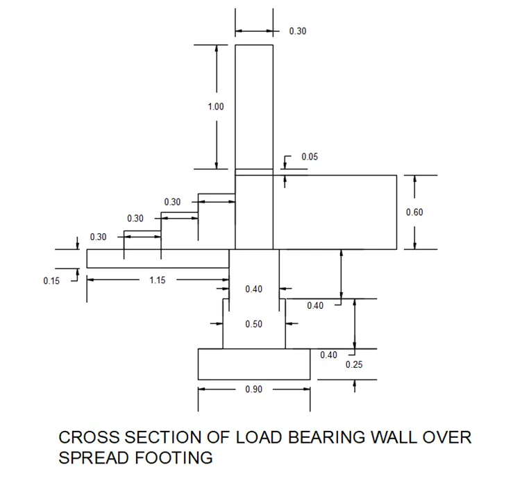
Procedure for C.S of load bearing wall over spread footing:
-Type L command and specify the point,
- Specify the length 0.9 in X direction.
- Specify the next length 0.25 in Y direction.
- Specify the next length 0.9 in –ve X direction then close the command.
- Specify the point at left top corner of rectangle with length command specify the length in X direction as 0.2.
- Specify the length 0.5 in Y direction.
- Specify the length 0.05 in X direction.
- Specify the length 0.4 in X direction.
- Specify the length 1.65 in Y direction.
- Specify the length 0.3 in X direction.
- Specify the length 1.65in –v Y direction.
- Specify the length 0.05 in X direction.
- Specify he length 0.4 in –ve Y direction.
- Specify the length 0.05 in X direction.
- Specify he length 0.5 in –ve Y direction that line is touches to the rectangle.
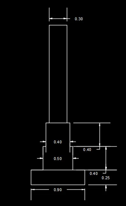
- Now specify the point a from that point specify the length 1.15 in –ve X axis.
- Specify the length 0.15 in –ve Y axis.
- Specify the length 1.15 in x direction.
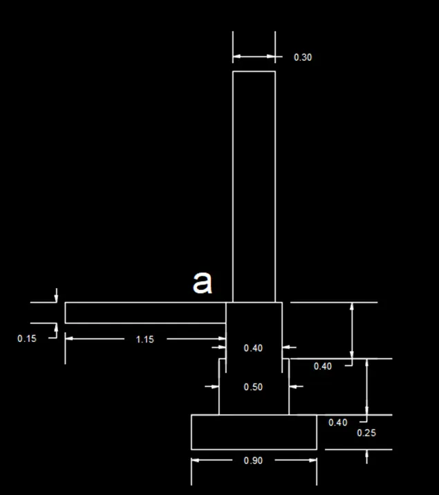
- Then specify the point b,
- From point b specify the length 3 in X axis.
- Specify the length 0.15 in Y axis.
- Specify the length 0.3 in X axis.
- Specify the length 0.15 in Y axis.
- Specify the length 0.3 in X axis.
- Specify the length 0.15 in Y axis.
- Specify the length 0.3 in X axis.
- Specify the length 0.15 in Y axis.
- Specify the length 0.3 in X axis.
- Then copy the length 0.3 last drawn line and paste at point C distance 0.05 in Y axis.
- Specify the point at D.
- Specify the length 1.0 in X axis.
- Speciy the length 0.6 in –ve Y axis.
- Specify the length 1.0 in –ve X axis.
- Then close the line command.
- Using DIMLINEAR command specified the length.
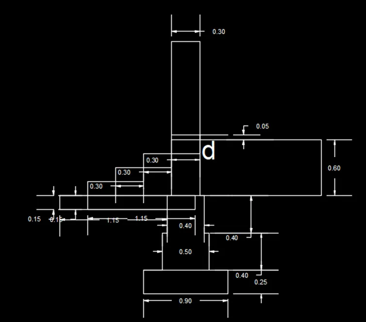
Question No 02: C.S. of load bearing wall over spread footing:
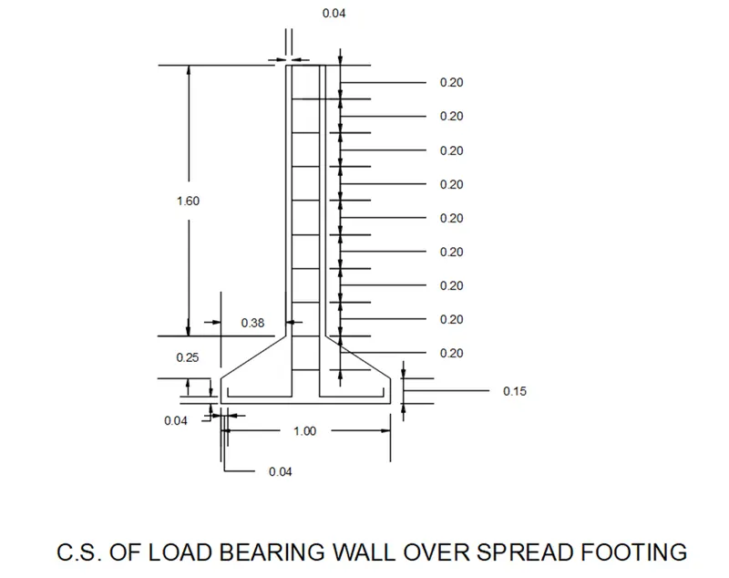
Procedure:
- Choose line command, specify the point and specify the length 0.15 in Y axis.
- Specify the length (@0.38,0.25), were @ indicates the length is starts from that point, 3.8 and 0.25 are values that are the in X and Y directions respectively.
- Then specify the length 1.6 in Y axis, length 0.24 in X axis, length 1.6 in –ve X axis, co-ordinate (@0.38,-0.25), Length 0.15 in –ve Y axis, and finally length 1.0 in –ve X axis.
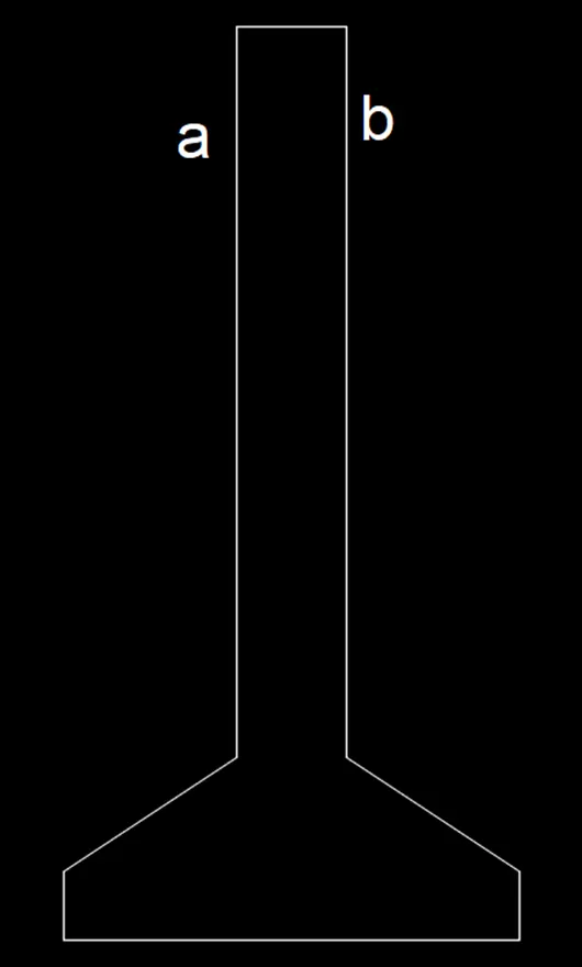
- Use the command Offset to the next step.
- Type O (offset) with through type command, specify the a line and move the cursor in X direction then give 0.04 length, Similarly to the b line and move the cursor in Y direction then give 0.04 length.
- Extend the both lines using Extend command upto base line.
- Join c, d & e line using Join
- Then use offset, Specify the line and enter the 0.04.
- Trim the extra lines from the drawing.
- Select the top line then copy the top line using Copy command and Array command,
- Enter the 10 number of arrays, specify the distance 0.2.
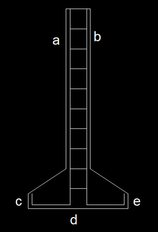
- Using DIMLINEAR command specified the length.
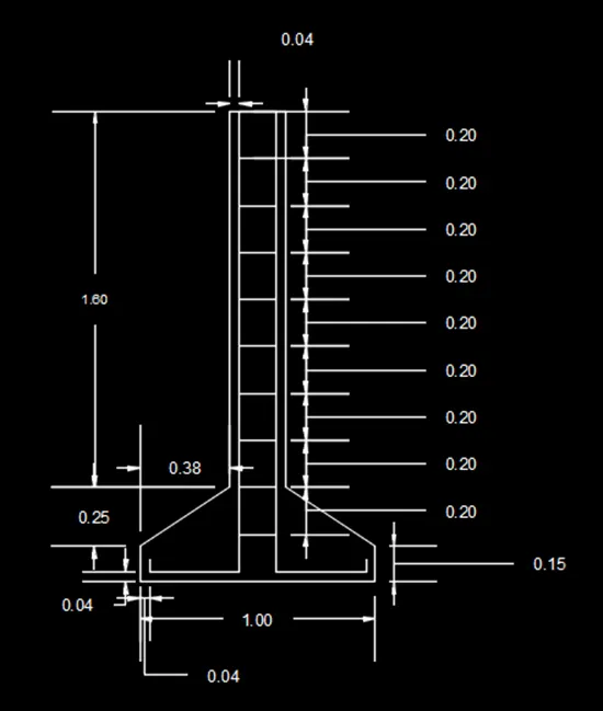
Question No 03: Line diagram of Two bedroom building:
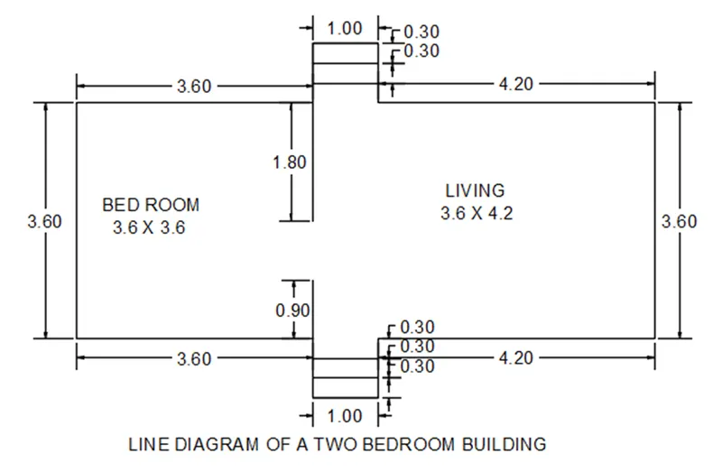
Procedure:
- Choose line command, specify the point and specify the length 3.6 in X axis, 0.9 in –ve Y axis, 1 in X axis, 0.9 in Y axis, 4.2 in X axis, 3.6 in Y axis, 4.2 in –ve Y axis, 0.9 in Y axis, 1 in –ve Yaxis, 0.9 in –ve X axis, 3.6 in –ve Y axis then close Line command
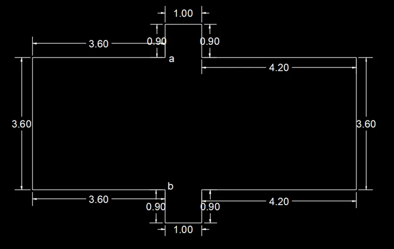
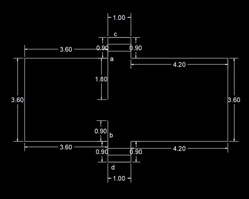
- Point a & b are specified in the above drawing, from point a length 1.8 in –ve Y axis, from point b length 0.9 in Y axis the line is created.
- At point c select the line and use Copy command then select the same line move the cursor in –ve Y axis then use Array command, Enter the 3 numbers of items to array and enter distance as 0.3.
- At point d select the line and use Copy command then select the same line move the cursor in –ve X axis then use Array command, Enter the 3 numbers of items to array and enter distance as 0.3.
- Enter the 3 numbers of items to array and enter distance as 0.3.
- Using DIMLINEAR command length is specified, then rooms are denoted with area.
Question No 04: C.S of Load bearing wall over Spread footing:
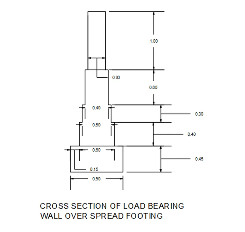
Procedure:
- Use Rectangle command specify the point, put (@0.9, 0.45).
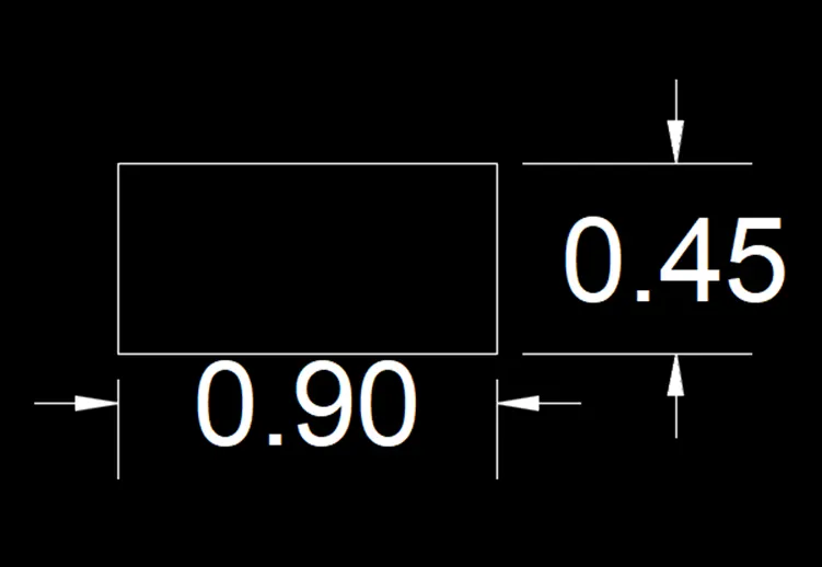
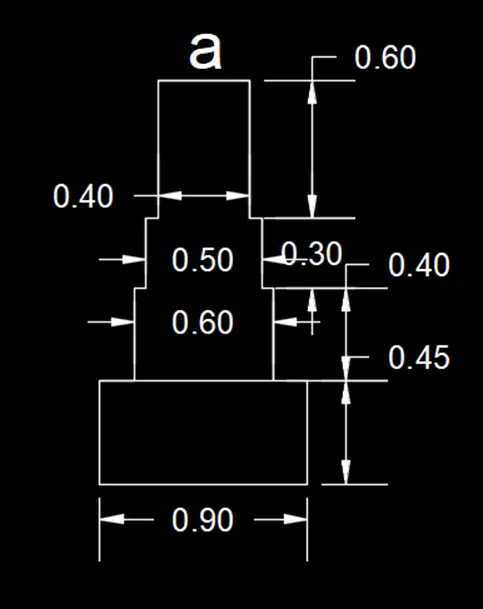
- Use Line command Specify the point A, from the point A draw a line with length 0.15 in X axis on Rectangle.
- Then move the cursor in Y axis, specify the length 0.4, then move the cursor in X axis with length 0.05, Consider length 0.5 in Y axis, 0.05 in X axis, 0.4 in Y axis, 0.05 in X axis, 0.6 in Y axis, 0.3 in X axis, 0.6 in –ve Y axis, 0.05 in X axis, 0.4 in –ve Y axis, 0.05 in X axis and finally 0.4 in -ve Y axis then t touches to the rectangle.
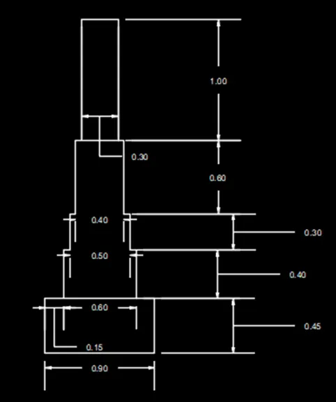
- Create a Rectangle with are of (@0.3,1), move that rectangle from command Move centre of the base line and place that rectangle on centre of the line
- Using DIMLINEAR command length is specified.
Question No 05: Isometric view of steps:
Procedure:
- Initially we need to On the Isometric
- 3 types of isometrics are presents, Those are
- Isoplane left,
- Isoplane Right,
- Isoplane Top.
Procedure for Isometric view of steps:
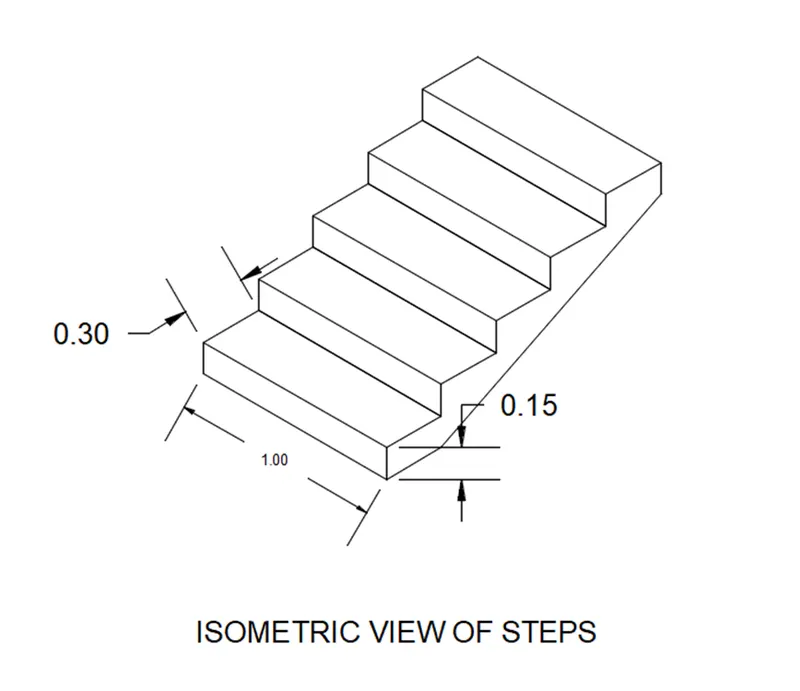
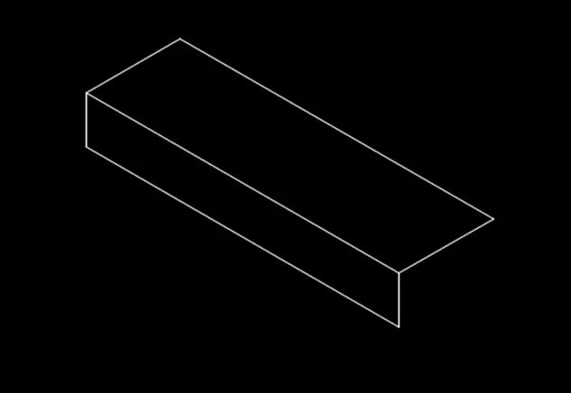
- Choose Isoplane left, Select the Line command, specify the point move the cursor down and mention length as 1.0, and mention length 0.15 in down, mention length as 1.0 in up and mention length as 0.15 in up.
- Change Isoplane left to Isoplane Right, From the last point mention the length as 0.3 in up, mention the length as 1.0 in down, and finally mention the length 0.3.
- Select the drawing and choose Copy command the select point a and paste in point b and paste continuous upto 5 steps.
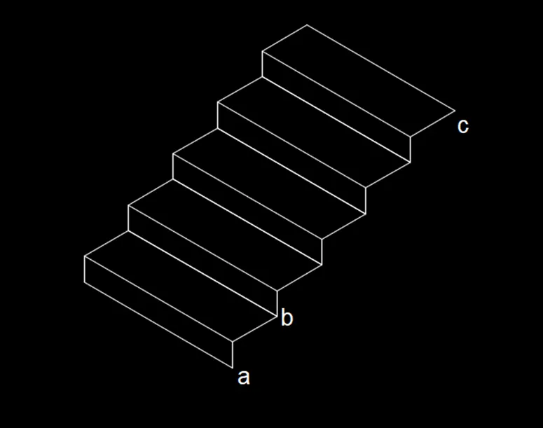
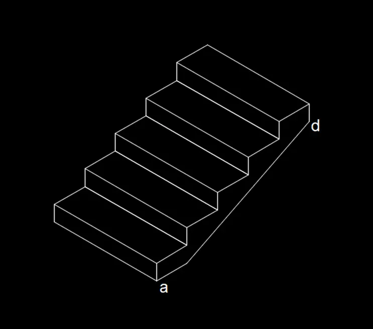
- From point c mention the length 0.15 to down is d.
- From point a mention the length 0.3 and join the point.
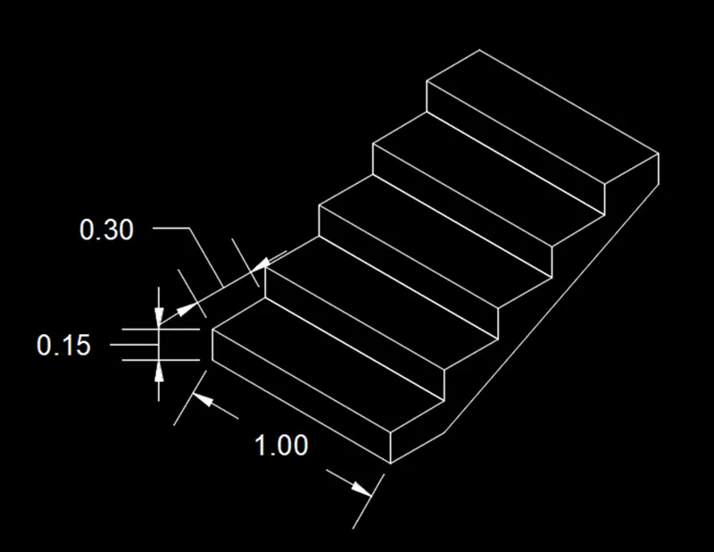
- Turn off the Ortho mode then Select the Linear dimension, And measure the length of drawing.
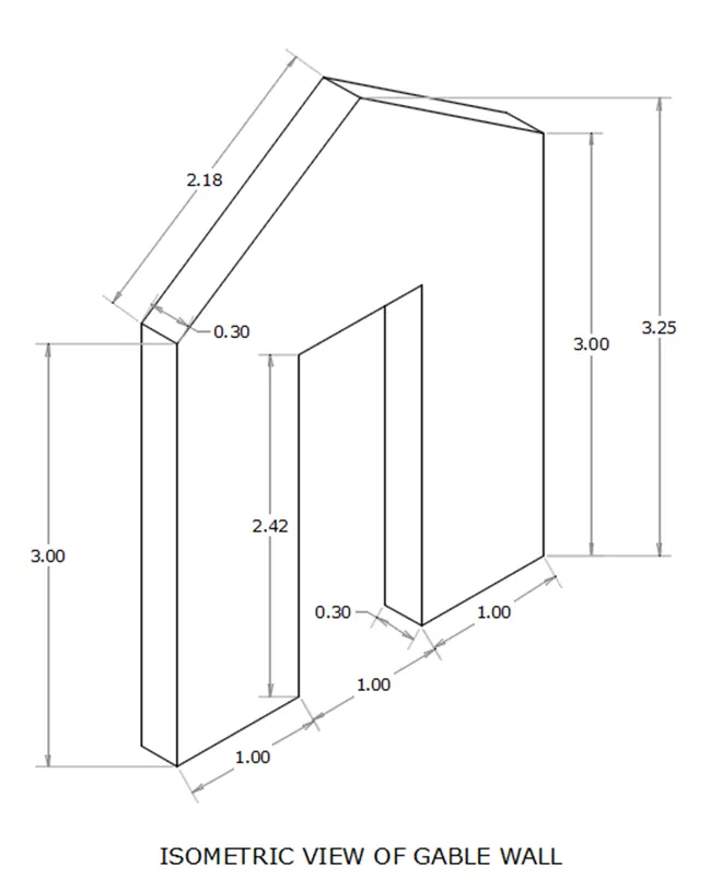
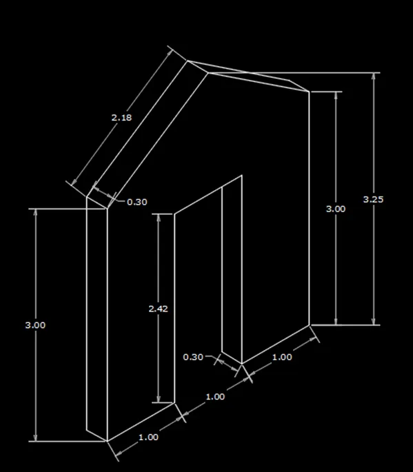
Question No 06: Isometric view of Gable Wall:
Procedure:
- Initially we need to On the Isometric
- 3 types of isometrics are presents, Those are
- Isoplane left,
- Isoplane Right,
- Isoplane Top.
Procedure for isometric view of Gable view:
- Choose Isoplane Right, choose line command, specify the point, mention the length 3 in down, mention the length 1.0 in right, mention the length 2.42 in up, mention the length 1.0 in right, mention the length 2.42 in down, mention the length 1.0 in right, mention the length 3.0 in up.
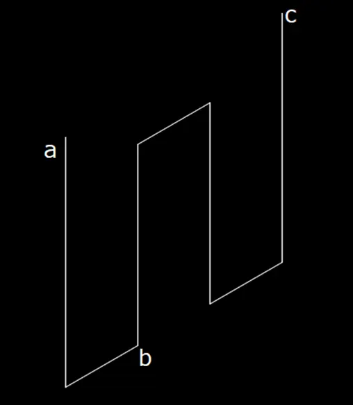
- Start the line command with b point, specify the length 0.5 in right and 4.0 in up.
- And join the line a & c to point
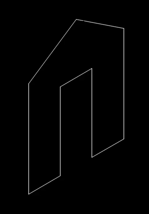
- Now change Isoplane Right command to Isoplane Left.
- Select the points a, c, d, e and f and using the line command mention the length 0.3 in all points and join the points.
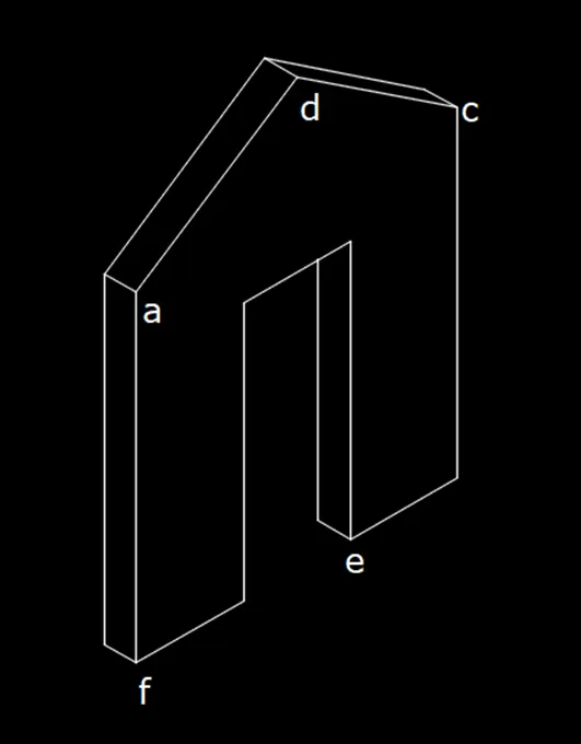
- Then Turn off the Ortho mode then Select the Linear dimension, And measure the length of drawing.
RESULT:
Created a Floor plan, Footing detail and Isometric view using AutoCAD and had good understanding about various tools in AutoCAD like the rectangle, polylines, modifications tools like copy, move, offset, Chamfor and modes like snap mode and ortho mode.