Project 1 _Creating an Architectural plan for the provided plot size and develop relevant basic structural drawings
Aim:
To Design and draft a layout of residential building east facing with plot size 20’x60’ with the following details
- Architectural drawing (floor plan, Elevations and sections)
- Structural Drawing (Column , footing and beam plan)
Introduction :
Various command used while Sketching :
- Line command
- Unit command
- Lim max command
- XL command
- Zoom command
- Arc command
- Trim command
- Text command
- Extent command
- Fillet command
- Rectangle command
- Circle command
- Copy command
- LT command
- Dimension command
- Layer command
- Offset command
- Limits command
PRODUCTRE :
STEP 1 :
- GO to START MENU ,select AutoCAD 2018.
- Enter “UNITS” command in the command tab.
- Open “ Drawing units “ dialogue box , Type as “ARCHITECTURAL ” and precision as 00
- Then click units scale to “INCHES ”
- Click “OK”.
- Enter “ LIM MAX” command in the command tab.
- Enter new value for Lim max as 200’.
- Enter “zoom” command in the command box.
- Enter “All” command in the command box.
- Enter “LIMITS” command in the command box.
- Specify lower left corner as
- Enter “zoom “ command in the command box.
- Enter “ALL” command in the command box.
Step 2:
CREATING GROUND FLOOR PLAN :
- Enter “XL “ (OR) “ X line” command in the command box.
- Specific a point as “Vertical” command in the command box.
- Move the line to somewhere , where you want
- Than click “ESC” command in the command box.
- Enter “XL “ (OR) “ X line” command in the command box.
- Specific a point as “Horizontal” command in the command box.
- Move the horizontal line to close to the vertical line.
- Than click “ESC” command in the command box.
- Create a box size of 20’ X60’
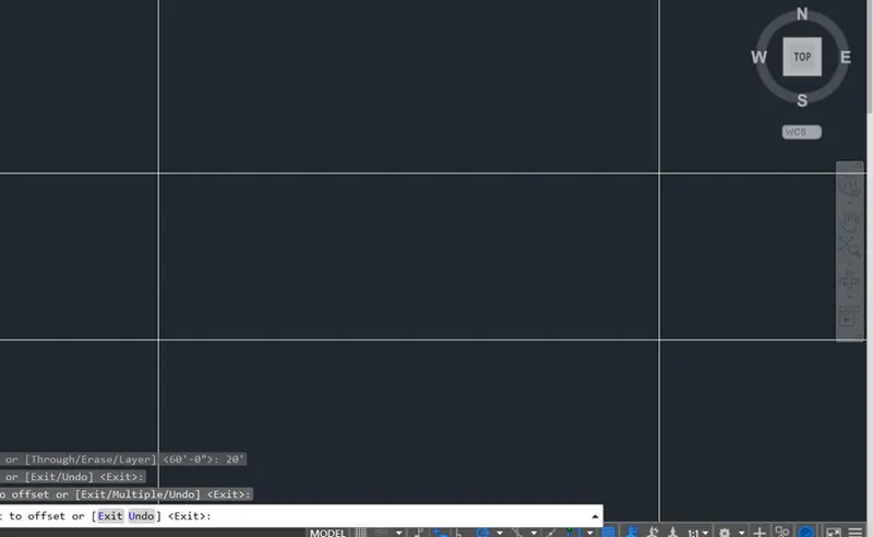
- Enter “OFFSET” command in the command box.
- Give a value of 9” in side of the box as external wall
- Will start create the from the right side.
- Enter “OFFSET” command in the command box.
- From the vertical external wall give a value of 16’-0” vertically
- Enter “OFFSET” command in the command box.
- From the Horizontal external wall give a value of 10’ horizontally
- Enter “OFFSET” command in the command box.
- Create a interwall size of 6” from the right side .
- Enter “OFFSET” command in the command box.
- From the right side internal wall give a value of 5’-8” as vertical line
- Enter “OFFSET” command in the command box.
- Create a interwall size of 6” from the right side .
- Enter “OFFSET” command in the command box.
- Give a value of 6’-8” from the horizontal external line
- Enter “OFFSET” command in the command box.
- Give a value of 6” for toilet wall vertically and horizontally
- Enter “OFFSET” command in the command box.
- Give a value of 5’-0” from the right side external wall.
- Enter “OFFSET” command in the command box.
- Give a value of 6” as internal wall vertically .
- Enter “OFFSET” command in the command box.
- Give a value of 8’-0” in horizontally as open area
- Enter “OFFSET” command in the command box.
- Give a value of 14’-6” from the open area in vertically.
- Enter “OFFSET” command in the command box.
- Give a value of 6” as interwall of Kitchen.
- Enter “OFFSET” command in the command box.
- Give a value of 18’-8” in vertically.
- Enter “OFFSET” command in the command box.
- Give a value of 17’-6” in vertically
- Give some space as entry
- Enter “OFFSET” command in the command box.
- Give a value of 7’-2” and 10’-6” as lawn
- Value of stairs tread depth as 7” and rise value as 5”
- I given windows and ventilator for more ventilation
- DOOR – 36”X 80”
- DOOR 1-2’6” X 7”
- WINDOW-24”X36”
- WINDOW 1-20”X 30”
- VENTILATION- 1’X2’
- Enter “MTEXT” in the command box .
- Give a value of 7 3/16"
- Enter “DIMLINER” command in the command box .
- Show the dimension as per the drawing
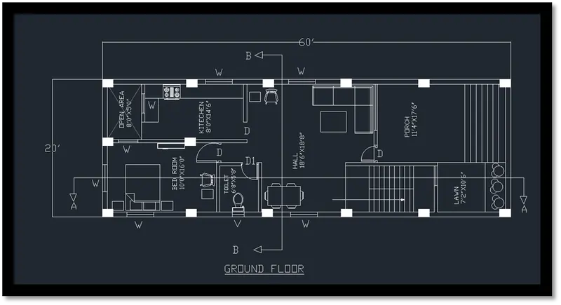
- Finally show the GROUND FLOOR drawing
RESULT :
Ground floor drawing result :
Step 3:
CREATING FIRST FLOOR PLAN :
- Enter “XL “ (OR) “ X line” command in the command box.
- Specific a point as “Vertical” command in the command box.
- Move the line to somewhere , where you want
- Than click “ESC” command in the command box.
- Enter “XL “ (OR) “ X line” command in the command box.
- Specific a point as “Horizontal” command in the command box.
- Move the horizontal line to close to the vertical line.
- Than click “ESC” command in the command box.
- Create a box size of 20’ X60’
- Enter “OFFSET” command in the command box.
- Give a value of 9” in side of the box as external wall
- Will start create the from the right side.
- Enter “OFFSET” command in the command box.
- From the vertical external wall give a value of 17’-4” vertically
- Enter “OFFSET” command in the command box.
- From the Horizontal external wall give a value of 10’ horizontally
- Enter “OFFSET” command in the command box.
- Create a interwall size of 6” from the right side .
- Enter “OFFSET” command in the command box.
- From the right side internal wall give a value of 4’-4” as vertical line
- Enter “OFFSET” command in the command box.
- Create a interwall size of 6” from the right side .
- Enter “OFFSET” command in the command box.
- Give a value of 6’-8” from the horizontal external line
- Enter “OFFSET” command in the command box.
- Give a value of 6” for toilet wall vertically and horizontally
- Enter “OFFSET” command in the command box.
- Now we are start creating O.T.S.
- Give a value of 9’-5” from the right side external wall.
- Enter “OFFSET” command in the command box.
- Give a value of 6” as internal wall vertically .
- Enter “OFFSET” command in the command box.
- Give a value of 8’-0” in horizontally as open area
- Enter “OFFSET” command in the command box.
- Give a value of 12’-6” from the open area in vertically.
- Enter “OFFSET” command in the command box.
- Give a value of 6” as interwall of Kitchen.
- Enter “OFFSET” command in the command box.
- Give a value of 4’-6” horizontally
- Enter “OFFSET” command in the command box.
- Give a value of 8’-0” in vertically
- Give a value of 18’-8” in vertically.
- Enter “OFFSET” command in the command box.
- From the toilet Give a value of 13’-6” in vertically
- Enter “OFFSET” command in the command box.
- Give a value of 12’-0” in horizontally
- Enter “OFFSET” command in the command box.
- Give a value of 11’-4” in horizontally
- Enter “OFFSET” command in the command box.
- Give a value of 13’-0” in horizontally
- Enter “TRIM “ command in the command box
- Trimmed unwanted line in drawing .
- Enter “OFFSET” command in the command box.
- Give a value of 7’-2” and 10’-6” as lawn
- Value of stairs tread depth as 7” and rise value as 5”
- I given windows and ventilator for more ventilation
- DOOR – 36”X 80”
- DOOR 1-2’6” X 7”
- WINDOW-24”X36”
- WINDOW 1-20”X 30”
- VENTILATION- 1’X2’
- Enter “MTEXT” in the command box .
- Give a value of 7 3/16"
- Enter “DIMLINER” command in the command box .
- Show the dimension as per the drawing
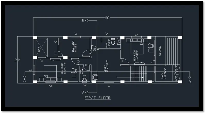
- Finally show the FIRST FLOOR drawing result
RESULT :
First floor drawing result :
Step 4:
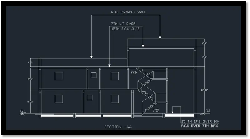
CREATING SECTION AA :
- Enter “XL “ (OR) “ X line” command in the command box.
- Specific a point as “Vertical” command in the command box.
- Move the line to somewhere , where you want
- Than click “ESC” command in the command box.
- Enter “XL “ (OR) “ X line” command in the command box.
- Specific a point as “Horizontal” command in the command box.
- Move the horizontal line to close to the vertical line.
- Than click “ESC” command in the command box.
- First will create length of the building Is 60’
- Enter “OFFSET” command in the command box.
- Give a value of 0” from the from the first horizontal line
- Enter “OFFSET” command in the command box.
- Again will create line from the first horizontal line value of 83”
- Will mentioned line as Ground Level
- Enter “OFFSET” command in the command box.
- From the ground level give a value of 8’-10” as ground floor
- Enter “OFFSET” command in the command box.
- From the ground floor will give a value of 8’-6” as first floor .
- Enter “OFFSET” command in the command box
- From the first floor give value of 3’-3” as parapet wall
- Enter “OFFSET” command in the command box
- Give a value of 8” as exterior wall thickness from the left side vertical line
- Enter “OFFSET” command in the command box
- Give a value of 16’-0” from the left side exterior wall.
- Enter “OFFSET” command in the command box
- Give a value of 6” as interior wall thickness.
- Enter “OFFSET” command in the command box
- From the interior wall give a value of 5’-8” as a toilet room
- Enter “OFFSET” command in the command box
- Give a value of 6” as toilet room wall thickness
- Enter “OFFSET” command in the command box
- Give a value of 18’-8” from the toilet wall room wall
- Created Hall as per the drawing
- Enter “OFFSET” command in the command box
- Give a value of 6” as wall thickness of hall
- Enter “TRIM” command in the command box
- Trimmed unwanted line in the section drawing .
FIRST FLOOR SECTION DRAWING :
- Enter “OFFSET” command in the command box
- Give a value of 17’-4” from the left side exterior wall.
- Enter “OFFSET” command in the command box
- Give a value of 6” as interior wall thickness.
- Enter “OFFSET” command in the command box
- From the interior wall give a value of 4’-4” as a toilet room
- Enter “OFFSET” command in the command box
- Give a value of 6” as toilet room wall thickness
- Enter “OFFSET” command in the command box
- Give a value of 12’-0” from the toilet wall room wall
- Created lobby as per the drawing
- Enter “OFFSET” command in the command box
- Give a value of 6” as wall thickness of lobby
- Enter “TRIM” command in the command box
- Trimmed unwanted line in the section drawing .
- Strat create stairs given trade value as 8”
- Given rise value as 23”
- Enter “OFFSET” command in the command box
- We given O.T.S value as 3’-3” in top the building .
- Enter “TRIM ” command in the command box
- Trimmed unwanted line in the drawing
- WINDOW-24”X36”
- WINDOW 1-20”X 30”
- VENTILATION- 1’X2’
- Enter “MTEXT” in the command box .
- Give a value of 7 3/16"
- Enter “DIMLINER” command in the command box .
- Show the dimension as per the drawing
- Finally show the SECTION -AA drawing result
RESULT OF SECTION AA:
STEP 5:
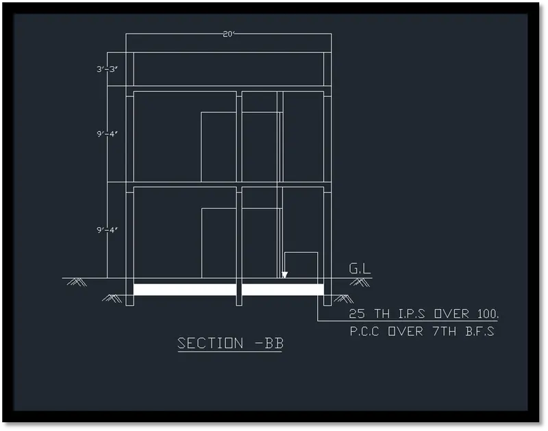
Creating section BB:-
- Enter “XL “ (OR) “ X line” command in the command box.
- Specific a point as “Vertical” command in the command box.
- Move the line to somewhere , where you want
- Than click “ESC” command in the command box.
- Enter “XL “ (OR) “ X line” command in the command box.
- Specific a point as “Horizontal” command in the command box.
- Move the horizontal line to close to the vertical line.
- Than click “ESC” command in the command box.
- First will create cross section length of the building Is 20’
- Enter “OFFSET” command in the command box.
- Give a value of 9” from the horizontal line.
- Enter “OFFSET” command in the command box.
- Give a value of 8” from the first horizontal line.
- Enter “OFFSET” command in the command box.
- Give a value of 9’-4” from the ground level.
- Enter “OFFSET” command in the command box.
- Give a value of 6” from the previous line .
- Enter “OFFSET” command in the command box.
- Give a value of 9’-4” from the first floor.
- Enter “OFFSET” command in the command box.
- Give a value of 6” from the previous line .
- Enter “OFFSET” command in the command box.
- Give a value of 3’-3” from the first floor as parapet wall.
- Enter “OFFSET” command in the command box.
- Give a value of 8” from the previous vertical line .
- Enter “OFFSET” command in the command box.
- Give a value of 18’-8” from the left side wall
- Enter “OFFSET” command in the command box.
- Give a value of 8” from the previous vertical line .
- Enter “OFFSET” command in the command box.
- Give a value of 10’ from the left main wall
- Enter “OFFSET” command in the command box.
- Give a value of 6”from the previous line .
- Enter “OFFSET” command in the command box.
- From the internal wall give value of 3’-5”
- Enter “OFFSET” command in the command box.
- Give a value of 6”from the previous line .
- Same like in first floor also .
- Enter “TRIM ” command in the command box
- Trimmed unwanted line in the drawing
- DOOR – 36”X 80”
- DOOR 1-2’6” X 7”
- Enter “MTEXT” in the command box .
- Give a value of 7 3/16"
- Enter “DIMLINER” command in the command box .
- Show the dimension as per the drawing
- Finally show the SECTION -BB drawing result
RESULT OF SECTION BB:
STEP 6:
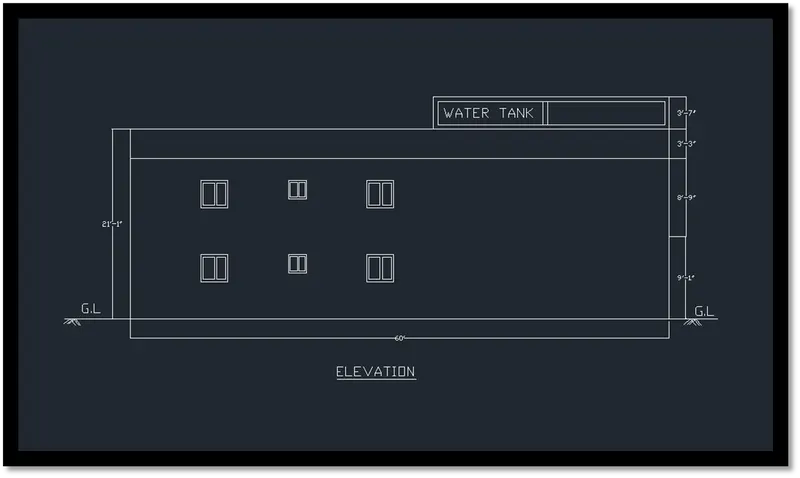
ELEVATION OF BUILDING :
- Enter “XL “ (OR) “ X line” command in the command box.
- Specific a point as “Vertical” command in the command box.
- Move the line to somewhere , where you want
- Than click “ESC” command in the command box.
- Enter “XL “ (OR) “ X line” command in the command box.
- Specific a point as “Horizontal” command in the command box.
- Move the horizontal line to close to the vertical line.
- Than click “ESC” command in the command box.
- Create a Length is 60’ horizontally
- Enter “OFFSET” command in the command box .
- Give value of 9’-1” from the previous line
- Enter “OFFSET” command in the command box .
- Give value of 8’-9” from the previous line
- Enter “OFFSET” command in the command box .
- Give value of 3’-3” from the previous line as parapet wall
- Enter “OFFSET” command in the command box .
- From the parapet wall give a value of 3’-7” as water tank
- Enter “TRIM “ command in the command box.
- Trimmed unwanted lines in the drawing
- Change the line in centre line
- WINDOW-24”X36”
- WINDOW 1-20”X 30”
- VENTILATION- 1’X2’
- Enter “TEXT” command in the command
- Mentioned the ELEVATION
- Enter “DIMLINER” command in command box
- Show the dimension in the plinth beam drawing .
- Finally show the elevation drawing results
RESULT OF ELEVATION:
STEP 7:
STRUCTURAL DRAWING :
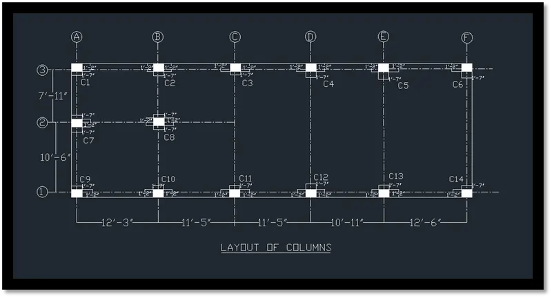
Creating Ground & First floor columns:-
- Enter “XL “ (OR) “ X line” command in the command box.
- Specific a point as “Vertical” command in the command box.
- Move the line to somewhere , where you want
- Than click “ESC” command in the command box.
- Enter “XL “ (OR) “ X line” command in the command box.
- Specific a point as “Horizontal” command in the command box.
- Move the horizontal line to close to the vertical line.
- Than click “ESC” command in the command box.
- Create a box size of 20’ X60’
- Enter “Line” command in the command box.
- Give a value of 1’-2” horizontally
- And give a value of 1’-7”
- Create like box as column 1 (C1) from the top left corner side .
- Enter “Line” command in the command box.
- Give a value of 1’-2” horizontally
- And give a value of 1’-7”
- Give a value of 1’-2” horizontally
- Create like box as column 2 (C2) from the distance of
- Enter “Line” command in the command box.
- Give a value of 1’-2” horizontally
- And give a value of 1’-7”
- Give a value of 1’-2” horizontally
- Create like box as column 3 (C3) from the distance of
- Enter “Line” command in the command box.
- Give a value of 1’-2” horizontally
- And give a value of 1’-7”
- Give a value of 1’-2” horizontally
- Create like box as column 4 (C4) from the distance of
- Enter “Line” command in the command box.
- Give a value of 1’-2” horizontally
- And give a value of 1’-7”
- Give a value of 1’-2” horizontally
- Create like box as column 5 (C5) from the distance of
- Enter “Line” command in the command box.
- Give a value of 1’-2” horizontally
- And give a value of 1’-7”
- Create like box as column 6 (C6) from the top Right corner side .
- Enter “Line” command in the command box.
- And give a value of 1’-7”
- Give a value of 1’-2” vertically
- And give a value of 1’-7”
- Create like box as column 7 (C7) from the distance of
- Enter “Line” command in the command box.
- And give a value of 1’-7” vertically
- Give a value of 1’-2” horizontally
- And give a value of 1’-7” vertically
- Give a value of 1’-2” horizontally
- Create like box as column 8 (C8) from the distance of
- Enter “Line” command in the command box.
- Give a value of 1’-2”
- And give a value of 1’-7” horizontally
- Create like box as column 9 (C9) from the down left corner side .
- Enter “Line” command in the command box.
- Give a value of 1’-2”
- And give a value of 1’-7”
- Give a value of 1’-2”
- Create like box as column 10 (C10) from the distance of
- Enter “Line” command in the command box.
- Give a value of 1’-2”
- And give a value of 1’-7”
- Give a value of 1’-2”
- Create like box as column 11 (C11) from the distance of
- Enter “Line” command in the command box.
- Give a value of 1’-2”
- And give a value of 1’-7”
- Give a value of 1’-2”
- Create like box as column 12 (C12) from the distance of
- Enter “Line” command in the command box.
- Give a value of 1’-2”
- And give a value of 1’-7”
- Give a value of 1’-2”
- Create like box as column 13 (C13) from the distance of
- Enter “Line” command in the command box.
- Give a value of 1’-2”
- And give a value of 1’-7”
- Create like box as column 14 (C14) from the down Right corner side .
- Enter “HATCH” command in the command box.
- Fill the box in the concrete .
- Enter “DIMLINER” command in the command box .
- Mention and show the dimension in the drawings
- Enter “MTEXT” command in the command
- Give a text as the dimension and drawings
- Finally the columns drawing in the result .
Result of Ground & First floor columns:-
STEP 8:
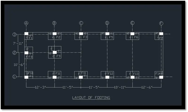
CREATING FOOTING GROUND & FIRST FLOOR :
- Enter “XL “ (OR) “ X line” command in the command box.
- Specific a point as “Vertical” command in the command box.
- Move the line to somewhere , where you want
- Than click “ESC” command in the command box.
- Enter “XL “ (OR) “ X line” command in the command box.
- Specific a point as “Horizontal” command in the command box.
- Move the horizontal line to close to the vertical line.
- Than click “ESC” command in the command box.
- Create a box size of 20’ X60’
- Enter “Line” command in the command box.
- from the first column give a value of 2’ Create box horizontally and vertically
- Create like a box , give name as footing 1 (F1)
- Enter “Line” command in the command box.
- From the 2nd (C2) columns give value of 2’ create footing like box .
- Mention that footing as (F2)
- Enter “Line” command in the command box.
- From the 3RD (C3) columns give value of 2’ create footing like box .
- Mention that footing as (F3)
- Enter “Line” command in the command box.
- From the 4TH (C4) columns give value of 2’ create footing like box .
- Mention that footing as (F4)
- Enter “Line” command in the command box.
- From the 5TH (C5) columns give value of 2’ create footing like box .
- Mention that footing as (F5)
- Enter “Line” command in the command box.
- From the 6TH (C6) columns give value of 2’ create footing like box .
- Mention that footing as (F6)
- Enter “Line” command in the command box.
- From the 7TH (C7) columns give value of 2’ create footing like box .
- Mention that footing as (F7)
- Enter “Line” command in the command box.
- From the 8TH (C8) columns give value of 2’ create footing like box .
- Mention that footing as (F8)
- Enter “Line” command in the command box.
- From the 9TH (C9) columns give value of 2’ create footing like box .
- Mention that footing as (F9)
- Enter “Line” command in the command box.
- From the 10TH (C10) columns give value of 2’ create footing like box .
- Mention that footing as (F10)
- Enter “Line” command in the command box.
- From the 11TH (C11) columns give value of 2’ create footing like box .
- Mention that footing as (F11)
- Enter “Line” command in the command box.
- From the 12TH (C12) columns give value of 2’ create footing like box .
- Mention that footing as (F12)
- Enter “Line” command in the command box.
- From the 13TH (C13) columns give value of 2’ create footing like box .
- Mention that footing as (F13)
- Enter “Line” command in the command box.
- From the 14TH (C14) columns give value of 2’ create footing like box .
- Mention that footing as (F14)
- Enter “DIMLINER” command in the command box .
- Mention and show the dimension in the drawings
- Enter “MTEXT” command in the command
- Give a text as the dimension and drawings
- Finally the footing drawing in the result .
STEP 9:
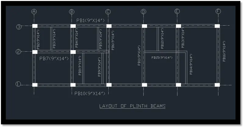
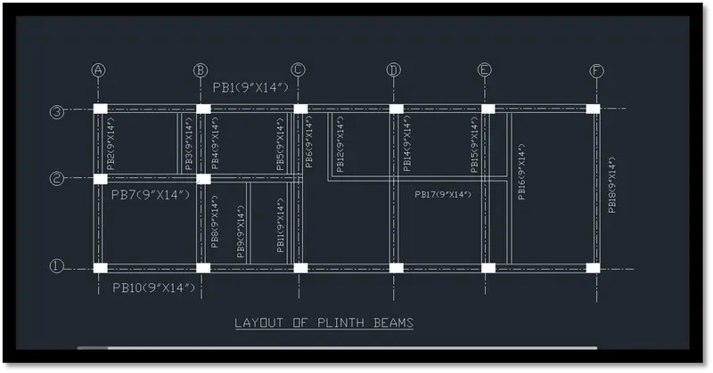
CREATING PLINTH BEAM DRAWING FOR GROUND FLOOR AND FIRST FLOOR:
- Enter “XL “ (OR) “ X line” command in the command box.
- Specific a point as “Vertical” command in the command box.
- Move the line to somewhere , where you want
- Than click “ESC” command in the command box.
- Enter “XL “ (OR) “ X line” command in the command box.
- Specific a point as “Horizontal” command in the command box.
- Move the horizontal line to close to the vertical line.
- Than click “ESC” command in the command box.
- Create a box size of 20’ X60’
- Enter “LINE” command in the command box .
- Give value of 9”X14” from the rectangular box inside .
- Enter “TRIM “ command in the command box.
- Trimmed unwanted lines in the drawing
- Change the line in centre line
- Enter “TEXT” command in the command
- Mentioned the plinth beams (BP 1 TO BB17)
- Enter “DIMLINER” command in command box
- Show the dimension in the plinth beam drawing .
- Finally show the plinth beam drawing results
RESULT OF PLINTH BEAM DRAWING
RESULTS:
1. Architectural Drawing (Floor Plan, Elevations, and Sections)
2. Structural Drawing (Column, Bean, Footing Plan)