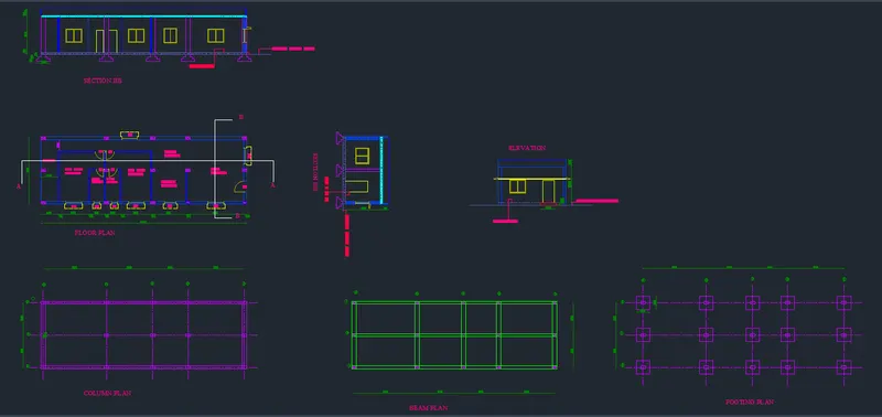
Project 1 _Creating an Architectural plan for the provided plot size and develop relevant basic structural drawings
1Q.
AIM:
Design and Draft a layout of a residential building with the following details:
a. Plot Size: 60’x20’(18.3m x6m)
b. Orientation- Facing East
c. Develop the following: 1. Architectural Drawing (Floor Plan, Elevations, and Sections) 2. Structural Drawing (Column, Bean, Footing Plan)
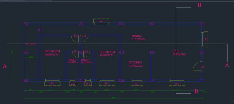
FLOOR PLAN
PROCEDURE:
Type UN and press enter
Under Drawing Units, select decimal
Now the lower limit is set to 0, 0 and upper limit to 1000, 1000
Type Z enter to zoom and A enter to all
Using the construction line command XL horizontal and vertical lines was created.
Draw the extenal walls of the plan by using the OFFSET ,TRIM commands take the exxternal wall dimensions as 250.
By using the LA command create the individual layers for all.

Now create the NEW LAYER and name it as EXTERNAL WALLS and draw the Internal walls of the plan using OFFEST,TRIM commands wall dimmensions are 125.
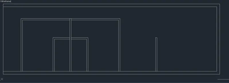
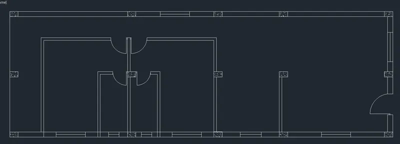
Now create the COLUMNS in layer properties and Draw the columns to the plan dimensions are
400x200,using the HATCH command hatch at the COLUMNS.
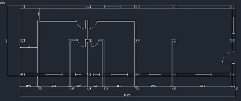
Create the new LAYER in layer properties and give the dimensions to the plan required.Using DIMLIN,DIMCONT commands
Create the new layer on layer properties and TEXT to the plan using the MTEXT command.
Select appropreate COLOUR to the in the LAYER PROPERTIES as shown below.
SECTION AA
PROCEDURE:
Now using the CONSTRUCTION LINE command XL and selecting the VERTICAL line draw the projectionS.
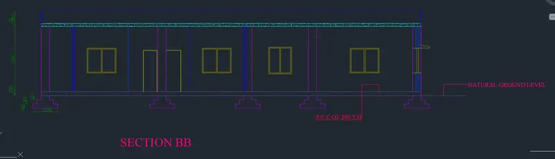
By using the OFFSET command draw the INTERIOR WALLS and EXTERIOR WALLS of the section AA by observing the section.
Draw a horizontal take it as GROUNND LEVEL.
Using OFFSET 200 thickness of P.C.C.
OFFSET OF 900mm SILL LEVEL.
OFFSET of 2100 LINTEL LEVEL.
OFFSET OF 3300 SLAB,150mm SLAB THICKNESS.
OFFSET PARAPET WALL OF 600 mm, from slab thickness.
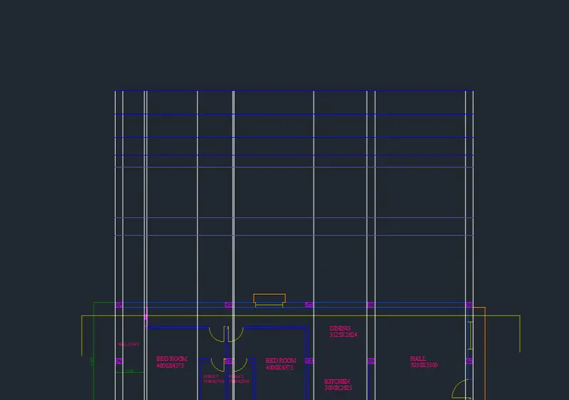
Now using the TRIM command trim the lines.Proper hathing for the SLAB and P.C.C
Draw the footings of the COLUMN as shown in the below.
Now give the dimensions to the section required.Using DIMLIN,DIMCONT commands.
TEXT to the SECTION using the MTEXT, MULTI LEADERcommand.
SECTION BB
PROCEDURE:
Now using the CONSTRUCTION LINE command XL and selecting the HORIZONTAL lines draw the projections.
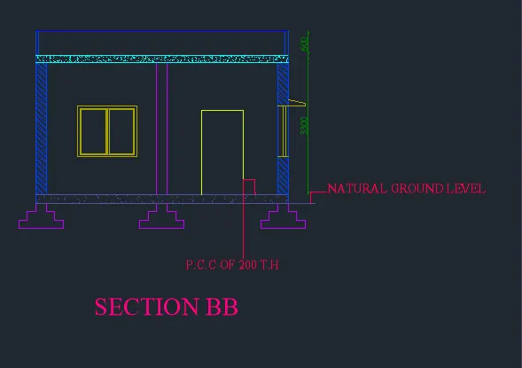
By using the OFFSET command draw the INTERIOR WALLS and EXTERIOR WALLS of the section BB by observing the section.
Draw a VEERTICAL take it as GROUNND LEVEL.
Using OFFSET 200 thickness of P.C.C.
OFFSET OF 900mm SILL LEVEL.
OFFSET of 2100 LINTEL LEVEL.
OFFSET OF 3300 SLAB,150mm SLAB THICKNESS.
OFFSET PARAPET WALL OF 600 mm, from slab thickness.
Now using the TRIM command trim the lines.Proper hathing for the SLAB and P.C.C
Draw the footings of the COLUMN as shown in the below.
Now give the dimensions to the section required.Using DIMLIN,DIMCONT commands.
TEXT to the SECTION using the MTEXT, MULTI LEADERcommand.
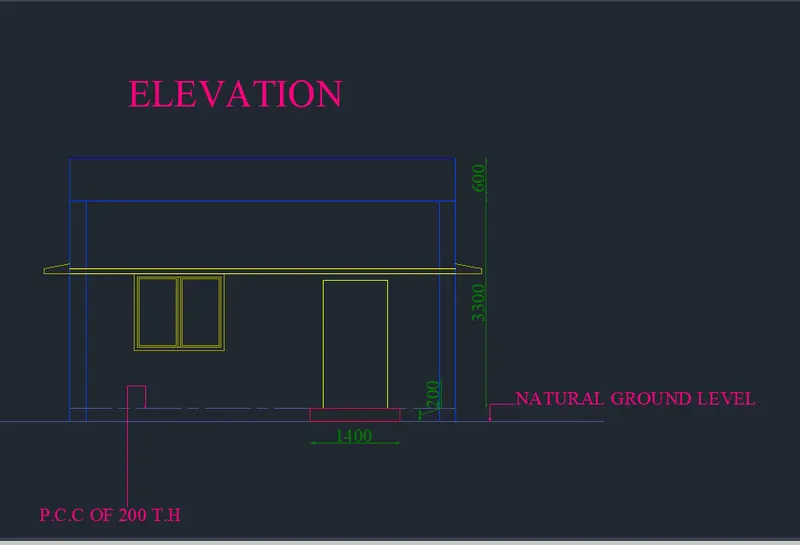
ELEVATION:
Now copy the SECTION BB and draw the ELEVATION.
TRIM the columns and internal walls and slab thickness.
Draw a SAJJA on the elevation of height above the 2300mm and thickness of 75mm.
Draw a STEP as 250mm TREAD,200mm RISE.
Now give the dimensions to the section required.Using DIMLIN,DIMCONT commands.
TEXT to the SECTION using the MTEXT, MULTI LEADERcommand.
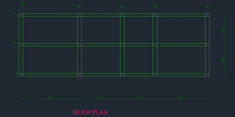
BEAM LAYOUT:
Turn off All the Layers except columns and center line.
Use the copy command and Select all the columns from plan view drawing and move them to a different position.
Using the LINE,SANP,ORTHO ON commands draw the line from one column at one end to another column end as shown in below.
Using the DIMLIN,DIMCONT give the dimensions to the LAYOUT.
Using the MTEXT command name the columns as shown in the PICTURE.
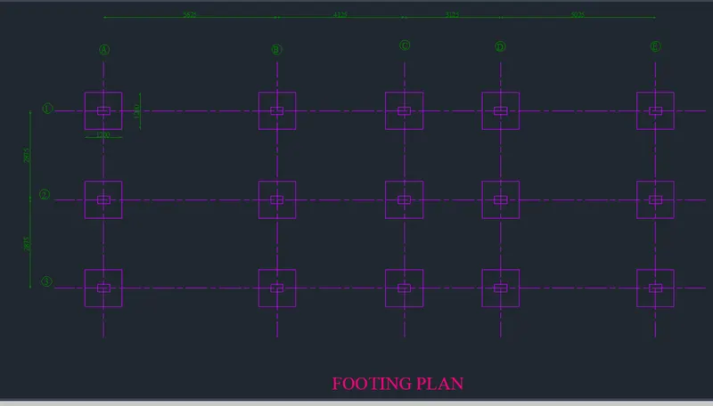
FOOTINNG PLAN:
Turn off All the Layers except columns and center line.
Use the copy command and Select all the columns from plan view drawing and move them to a different position.
Using the LINE command and select the LINE TYPE draw center lines of the columns.
Using the LINE command 600 mm from center on all the sides draw the line,repeat same for each and every column.
Using the DIMLIN,DIMCONT give the dimensions to the LAYOUT.
Using the MTEXT command name the columns as shown in the PICTURE.
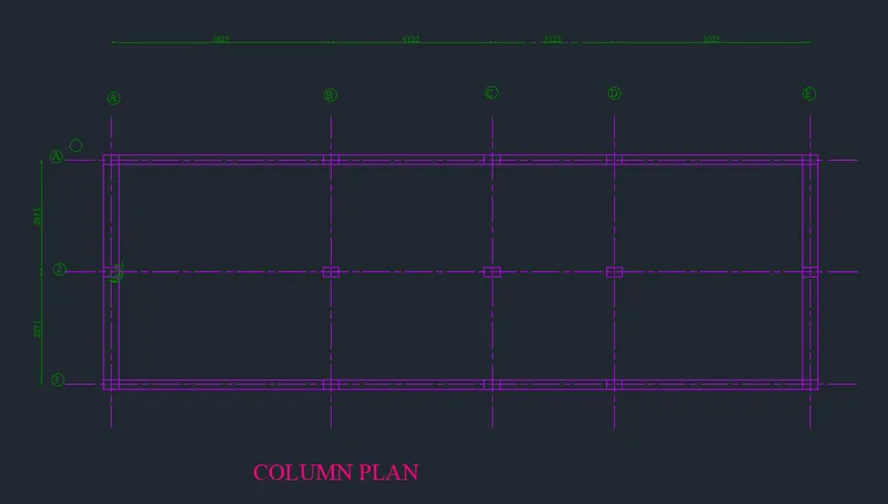
COLUMN PLAN:
Turn off All the Layers except columns and center line.
Use the copy command and Select all the columns from plan view drawing and move them to a different position.
Using the LINE command and select the LINE TYPE draw center lines of the columns.
Using the DIMLIN,DIMCONT give the dimensions to the LAYOUT.
Using the MTEXT command name the columns as shown in the PICTURE.
RESULT:
1.Architectural Drawing (Floor Plan, Elevations, and Sections) 2. Structural Drawing (Column, Bean, Footing Plan) are completed.