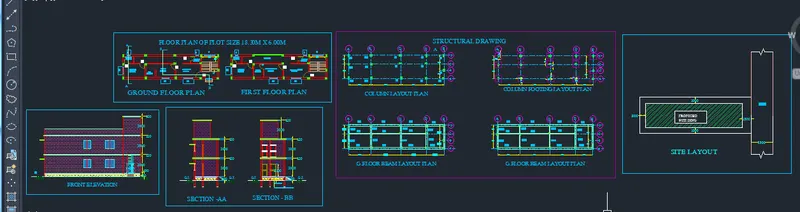
Project 1 _Creating an Architectural plan for the provided plot size and develop relevant basic structural drawings
PROJECT ON:
Creating an Architectural plan for the provided plot size and develop relevant basic structural drawings
AIM:-
To Design and Draft a layout of a residential building with the following details:
a. Plot Size: 60’x20’(18.3m x6m)
b. Orientation- Facing East
c. Develop the following: 1. Architectural Drawing (Floor Plan, Elevations, and Sections) 2. Structural Drawing (Column, Bean, Footing Plan)
- Architectural drawing
- Site plan
- Ground floor plan
- First floor plan
- Elevation
- Section
- Structural Drawing
- Colum layout plan
- Beam layout plan
- Footing layout plan
- INTRODUCTION:-
The general commands that are used for the drawing the architectural and structural plans by using the AutoCAD.
- Line
- Offset
- Trim
- Circle
- Rectangle
- Erase
- Blocks
- Text
- Dimensions
- Mirror
- Copy
- Rotate
- Move
Etc…..
PROCEDURE:-
To start the drawing
- Click on the AutoCAD application and open this application
- Type QNEW in command bar press enter
- Select the default setting as metric
- Type UNIT in command bar press enter
- Select the unit as Decimal – precision as 0 – milimeter
- Keep object snap, ortho>ON
- Keep snap and grid are OFF
Site plan:-
- Take the line command
- Specify the start point randomly
- Specify next point @18300<0
- Specify next point @6000<90
- Specify next point @18300<180
- Close
- Take the offset command
- Offset the top and bottom horizontal line specifying the distance as 1000 unit
- Offset the left vertical line taking distance 1000
- Offset the right vertical line taking distance 1500
- Again offset the line at 3500 units for the Road width
- Press ESC.
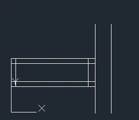
- trim all unwanted lines
- Take the breakline command
- Draw the breakline for road by at top and bottom
- Take the H command
- Select the ANSI32 , give the pattern size 1500
- Click the pick point inside the drawn box.
- Write the text and give the dimensions. By taking the colours and size.
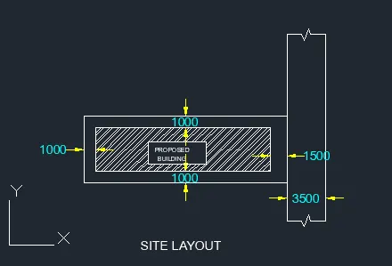
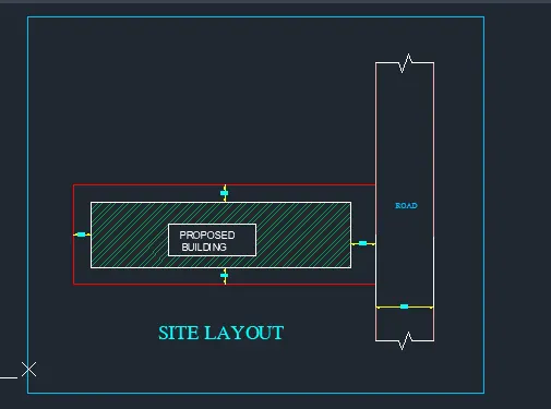
- Click on the layer properties , give the layers
RESULT:-
GROUND FLOOR PLAN AND FIRST FLOOR PLAN:-
- Take the line command , specify the start point anywhere on screen
- Specify next point as @15800<0
- Specify next point as @4000<90
- Specify next point as @15800<180
- Close
- Take offset at distance of 230 unit and click inside by selecting both right and left vertical lines and both top and bottom horizontal lines
- Take the offset again draw all the appropriate lines to create all the units of the plan
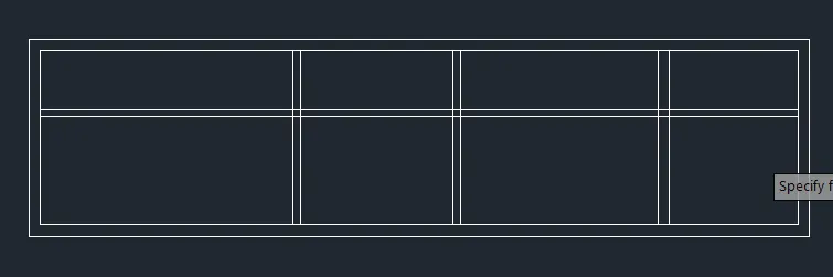
- and trim all the unnecessary lines
- Sizes of Door and windows:-
- W = 1800x1350
- W1= 1500x1350
- W2=1200x1350
- V=450x1050
- D1=1000X2100
- D2=900X2100
- D3=800X2100
- GATE opening size = 1100 mm width
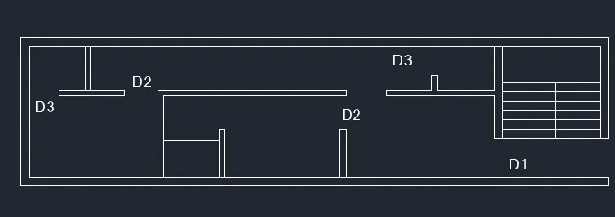
- Create all the opening by use of the line offset and trim command.
- To draw the door as the Block
- Take the line tool
- Draw the line of length 1000mm
- Take rec command , specify the size as 50x100mm
- Copy the rectangle and place on the corners of the line
- Trim the line by use of trim command
- Take the line command
- Specify the start point on the rectangle center of right vertical line
- Specify the distance as 20 <0
- Specify distance on 880<90
- Take the offset of that line at the 30 unit
- Take extend command and extent the h-line
- Take the circle command
- Pick the start point
- Specify the diameter of the circle as 1760
- Press enter
- Trim all the unwanted line
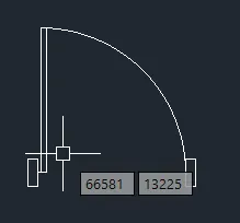
- Take B for block command press enter, give the name
- Enter
- Select the object and select the insertion point and press ok
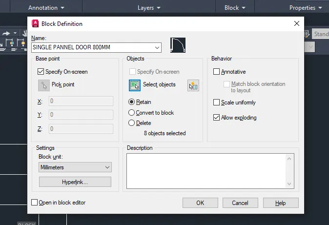
By following the above procedure the different doors and the windows drawn as Blocks
- Inset the block of doors and windows
- Place the blocks by selecting the proper positions.
- Create the steps at entrance of gate tread =250mm
- Draw that by use of line offset and trim tool.
- Draw the projected lines for the sunshade by selecting the lintype ISO Dashline , scale 10 unit
- Create all the projections for the window and ventilators.
STAIRCASE UNIT:-
- ASSUME Rise = 260mm and Tread=250mm
- Take the offset at 1000mm for the landing by selecting the top inner side H-line
- Offset bottom side of the lines at 250mm for treads six times
- Take the offset at 1200mm and 200mm ,select the vertical inner right side line
- Click at the left
- Here steps are divided into two part
- Trim all unwanted lines
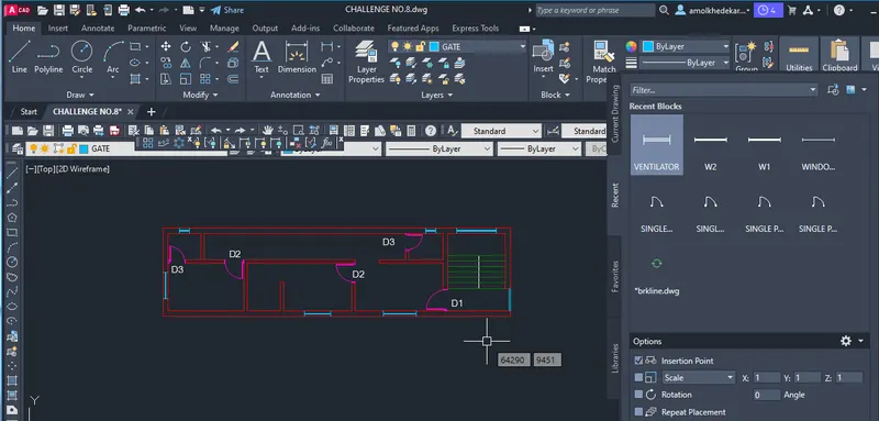
- Select the left side steps and make in invisible (means show it by linetype ISO dash lines choose the linetype scale as 10 unit) for ground floor plan
- Select the right side steps and make in invisible (means show it by linetype ISO dash lines choose the linetype scale as 10 unit) for ground floor plan
Column size = 250mmx 350mm
Take the rec command specifying start point randomly
Take the dimensions as length=250mm press enter and take width=350mm press enter
Select the column, take copy command
Place the column in the positions.
Here I rotate the column by giving the rotation angle as 90 and place in positions wherever I want.
Create all the columns. for the building
Creating of LAYER:-
- click on the layer properties
- click on the create new layer
- specify the names as wall, windows, steps,railing, column,doors, etc give the colour also.
RESULT:-
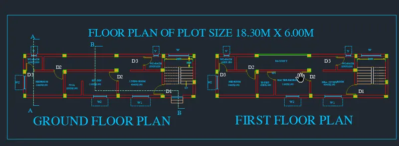
ELEVATION:-
- take the xline command
- draw the projection line by picking the point on that line which are visible in front of house
- take the line command and draw the line perpendicular to the projection line at bottom side by knowing the proper distance or height of the building
- take the offset command
- offset the line at the distances of 600mm, 900mm,2100mm,3000mm,120mm
- make the again offset from the slab line of the ground floor for the first floor and for the headroom
- trim all the unwanted lines.
- Take the H command select
- GRAVEL take the pattern scale as 500mm
- BRICK take the scale of pattern 1000
- Solid scale 1 create the hatches by taking the proper colours.
- Give the proper text and the dimensions.
RESULT:-
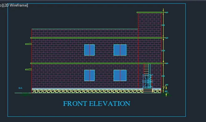
SECTION AT A-A AND SECTION B-B
- Take the line command
- Draw the vertical line of length as 17000mm
- Offset at 150 mm, click on left side of line
- Offset at 230mm, click on the right side
- Offset at 1200mm, click on right side
- Offset at 150mm, click on right side
- Offset at 2190mm, click on right side
- Offset at 150mm , click on right side
- Press ESC.
- Take the line command , draw the horizontal lines at bottom
- Take offset command
- Offset at 450mm for boulder filling thickness
- Offset at 150 mm for the p.c.c thickness
- Offset at 900mm for sill height
- Offset at 3000mm for ceiling
- Offset at 120 mm to show the slab thickness
- Repeat the same procedure above up to the height of the building
- Trim all unwanted line
- Take the H command select
- GRAVEL take the pattern scale as 500mm
- BRICK take the scale of pattern 1000
- AC CON and scale for the pattern as 20
- Solid scale 1 create the hatches by taking the proper colours.
- Give the proper text and the dimensions which is necessary for the sections.
RESULT:-
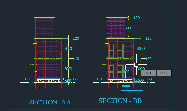
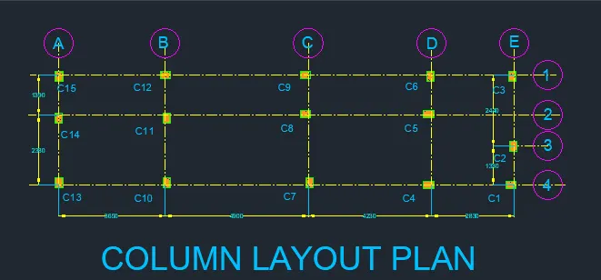
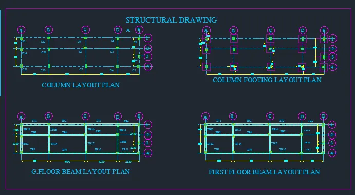
COLUMN LAYOUT PLAN:-
- copy the floor plan
- trim the lines / units excluding the column and walls
- take the center line command
- select the lines press enter
- like wise create all the vertical and horizontal center lines for the columns
- trim the wall lines using trim command
- create the circles at the ends of all center lines for the numbering the center lines as 1,2,3.. and A,B,C,D,E,F… ETC
give the text and the layers for the plans
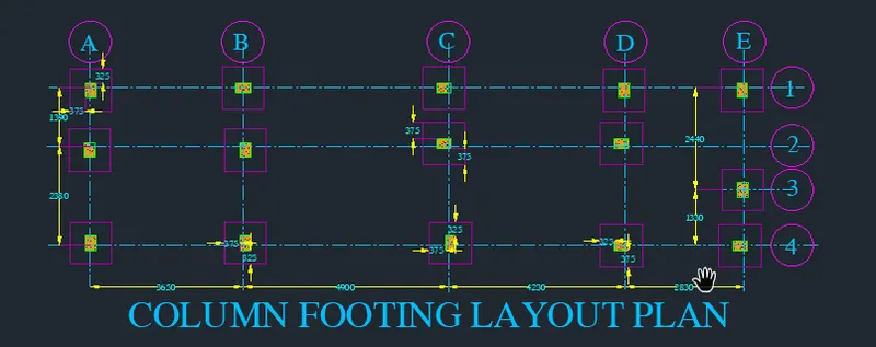
COLUMN FOOTING LAYOUT PLAN:-
- Copy the column layout plan
- Assume the size of footing as 1000x1000mm
- Take rec command specify the point anywhere
- Take the dimensions as length=1000mm and width=1000mm
- Press enter.
- Copy the rectangle
- Place the footing for column as shown in below drawing
- create the circles at the ends of all center lines for the numbering the center lines as 1,2,3.. and A,B,C,D,E,F… ETC
- give the text and the layers for the plans.
RESULT:-
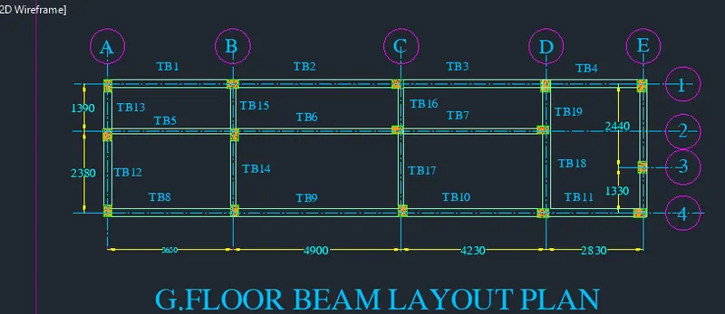
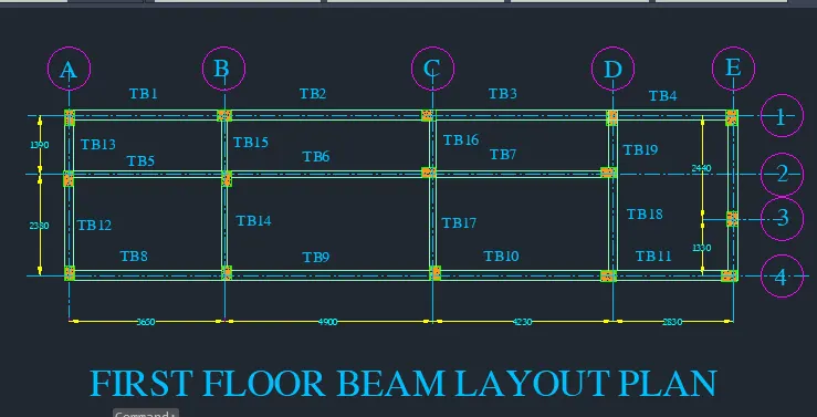
BEAM LAYOUT PLAN :-
FOR GROUND FLOOR AND FIRST FLOOR
- copy the floor plans
- trim the lines, units text excluding the column and the wall lines
- take the center line command
- width of beam as 230mm
- select the lines and make the center lines for the beam layout
- take the circle command select the center point as the end of any center line
- specify the Radius as 500 mm and press enter
- create the circles at the ends of all center lines for the numbering the center lines as 1,2,3.. and A,B,C,D,E,F… ETC
- give the text and the layers for the plans.
RESULT:-
RESULT WITH THE COMPLETE SET OF ARCHITECTURAL DRAWING:-
RESULT WITH THE COMPLETE SET OF STRUCTURAL DRAWING:-
COMPLETE SET OF DRAWINGS:-