Project 1 _Creating an Architectural plan for the provided plot size and develop relevant basic structural drawings
AIM : TO DRAFT THE PLAN IN THE PLOT SIZE 60’X20’ AND SKETCHING PLAN, ELEVATION, SECTION, LAYOUT OF BEAM , LAYOUT OF COLUMNS, LAYOUT OF FOOTINGS OF THE PLAN.
INTRODUCTION :
FOLLOWING TOOLS IN THE AUTO CAD ARE USED TO DRAW THE DRAWINGS :
- Line: Draw lines in AutoCAD
- Polygon: Draws polygons with three or more sides
- Rectangle: Used to draw rectangles
- Circle: Command used to draw circles
- Ellipse: Used to draw ellipse.
- Erase – Erase object in the drawing area
- Copy – Used to copy one or more objects
- Mirror – Command used to mirror an exact duplicate of an object.
- Offset – Used to offset one object from another a distance you specify
- Extend – Used to extend one line to another
- Array – Use to make a rectangular or polar array of an object
- Move – Used to move objects around in the drawing area
- Rotate – Used to rotate an object around a base point
- Scale – Command used to make an object larger or smaller
- Trim – Command used to trim an object from another object
- Chamfer – Used to put a chamfer between two lines
STEPS FOR DRAWING PLAN- (GROUND AND FIRST FLOOR PLAN)
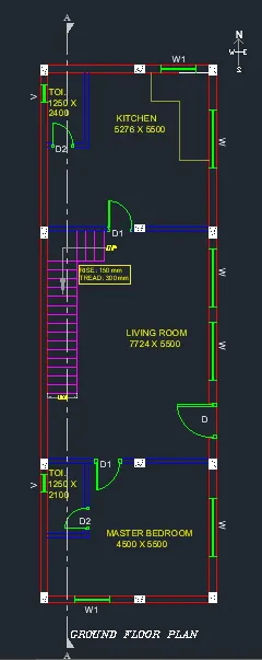
- Open auto Cad and enter UN (Units command) in the command box and select type as decimal and set precision of decimal as 0
- Select X line command and draw horizontal line and vertical line.
- Trim the unwanted line.
- Offset 250 as external wall to both horizontal and vertical line.
- Trim the corner points.
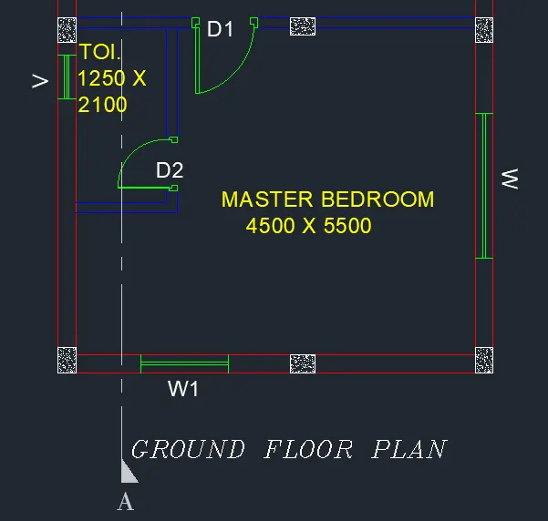
- Offset in X direction and in Y direction for bedroom.
- Offset 600 for shaft.
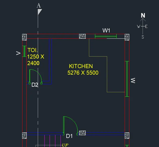
- Offset 1250 and 2100for toilet.
- Offset 150 for internal wall.
- Offset horizontal for kitchen and in vertical direction for kitchen.
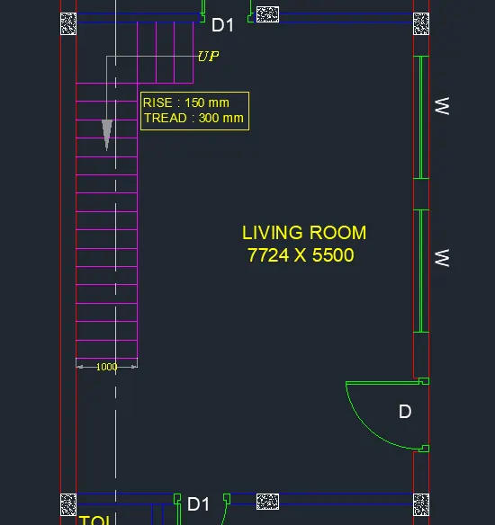
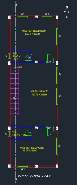
- Offset 1000 for landing o staircase.
- Offset 300 for tread of staircase.
Drawing of doors and windows- Line command is used for drawing of windows and doors.
Sizes of doors and windows are as follows
- Doors (DIMENSIONS ARE IN MM)
- D= 1200 X 2100.
- D1= 900 X 2100.
- D2= 750 X 2100.
- Windows & Ventilators (DIMENSIONS ARE IN MM)
- W= 20000 X 1200.
- W1= 1200 X 1200.
- V= 600 X 1050.
- Windows are drawn by using line command.
- Section lines are drawing by using layer and changing the layer type.
- Hatch- For hatching the columns type hatch in command box- open settings -select pattern- select pattern as AIR-CONC- select global scale factor as 0.7.
- Dimension- For drawing dimension using dimension tool in the ribbon.
- Text- For naming of plan use text in ribbon in that use multiline text and keep the height of text as 220.
GROUND FLOOR PLAN -
FIRST FLOOR PLAN -
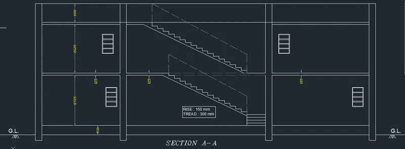
STEPS FOR DRAWING SECTION A-A -
- Rotate the entre plan drawn earlier in the 90 degrees direction to draw the section
- Select x line command and take the projectors of the rotated plan in the downward manner.
- Take the projections of all internal walls of 150 mm and external walls of 250mm.
- Offset 500 mm from the ground level.
- Offset 2725 for ground floor.
- Offset 2625 for second floor.
- Offset 1000 for parapet wall
- For drawing of staircase offset 300 for tread and offset 150 for rise of staircase.
- Draw the chajjas and windows as per the sizes considered and standards.
- Draw the railing of staircase in dash manner from the layers and change the layer to ACADISO03W100.
- Thickness of slab is 125mm.
- Offset 125 below the line of first floor of 2765.
- Give the dimensions by dim linear or dim continue command.
- Select the multiline text for naming of the section.
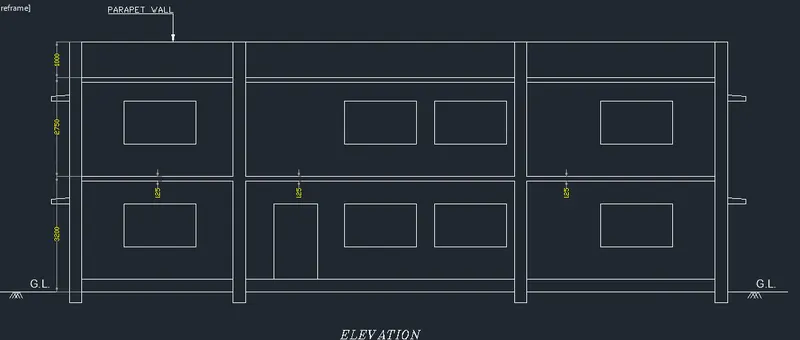
STEPS FOR DRAWING ELEVATION-
- Select x line command and extend the lines from the plan in the downward manner to create projections.
- Offset 500mm from the ground level for plinth
- Offset 2765 for ground floor.
- Offset 1000 for parapet wall.
- Draw the chajjas and windows as per the sizes considered and standards.
- Give the dimensions by dim linear or dim continue command.
- Select the multiline text for naming of the section.
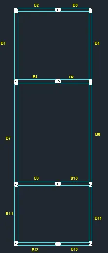
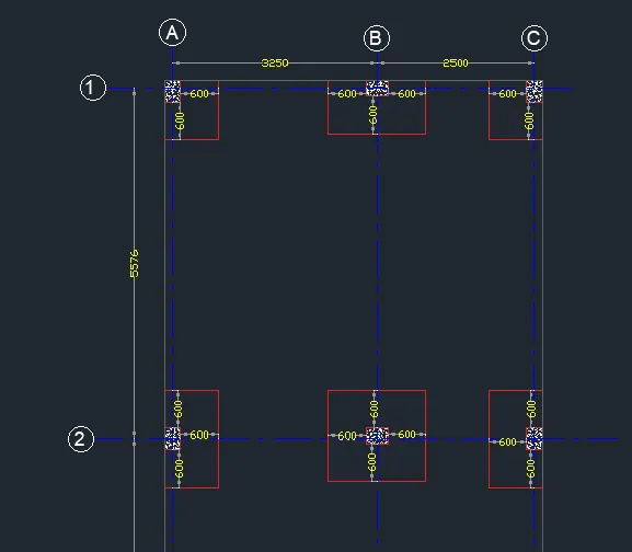
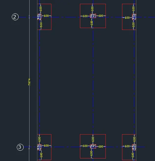
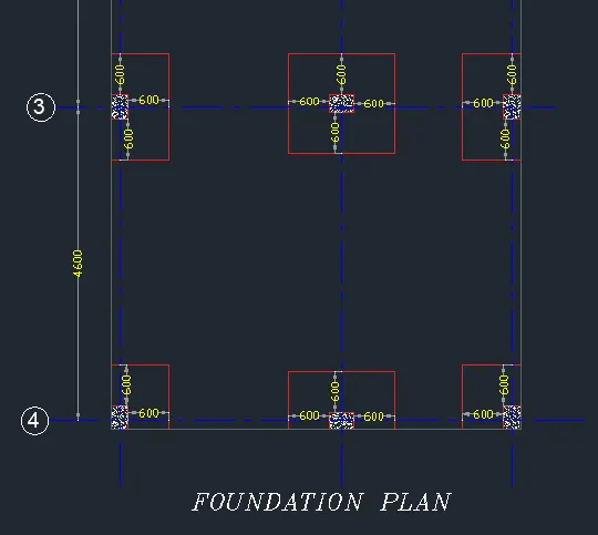
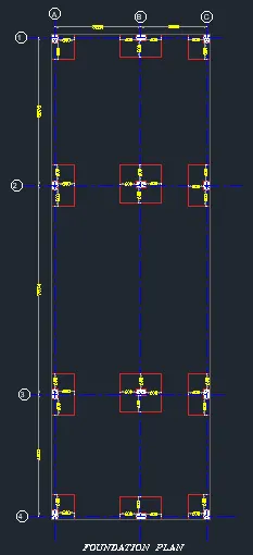
STEPS FOR DRAWING COLUMN LAYOUT, BEAM LAYOUT, FOOTING LAYOUT.
- Line command is used for drawing the layouts.
- Size of column is assumed as 250 x 350.
- Dim linear command is used for dimensions of centreline.
- Line type is changed from layer to continuous dash type.
- Hatch is used for hatching the columns as AIR CONC type.
COLUMN LAYOUT DRAWING -
BEAM LAYOUT DRAWING-