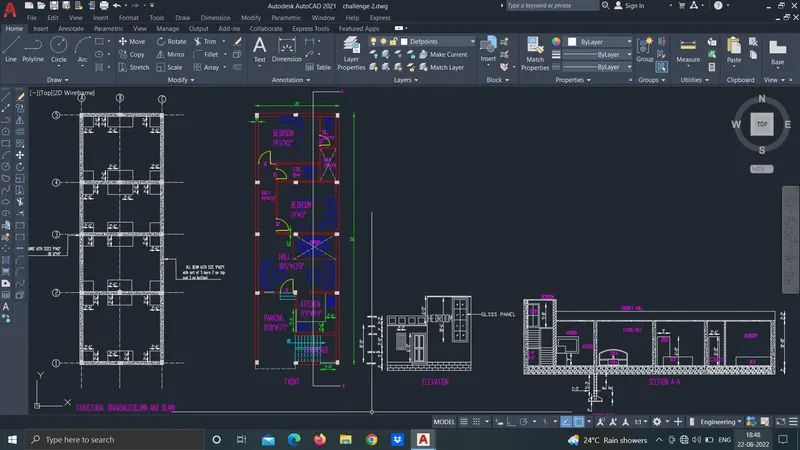
Project 1 _Creating an Architectural plan for the provided plot size and develop relevant basic structural drawings
AIM: Application of autoCAD to make drawings of building with dimension 20'*60' such structural drawings, plan, elevation and section of building.
INTRODUCTION: In this project, application of autoCAD is used to build plan of house, to make structural drawing beam and column, to make elvation of building and to make section of building.
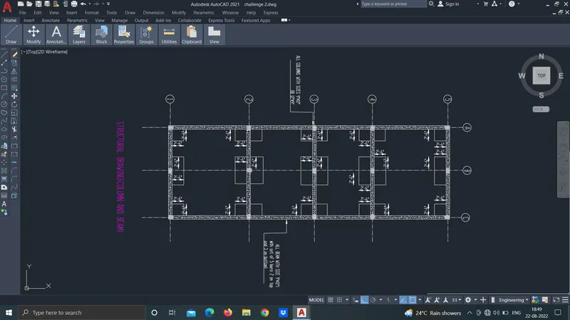
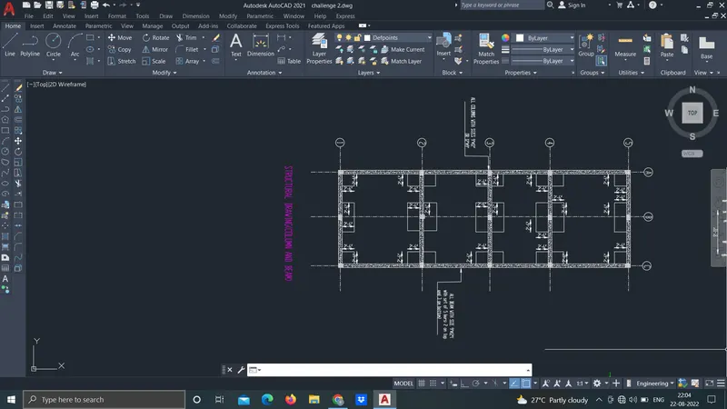
PROCEDURE FOR STRUCTURAL DRAWING : Following steps are used for making structural drawing.
- Set units and limits as per requirement.
- Draw outer line using center line.
- Offset the inner outer line using outer line with specifying distance.
- Mark column using rectangle.
- Size of column used as 9'*12' or 12'*9'.
- Draw excavated area using pl command.
- Dimension of excavated area is 2'6" from column corner on each side.
- Beam is drawn using pl command, join the all column with corner with perfect measurement.
- Make sure columns should be along the beams.
- From rebbon select text object then specify heigth of text then provide rotation angle of text.
For editing text used text edit command or double quick on text.
- According to requirement single and double text is used.
- For setting of text command ST and set diallog box.
- In this drawing, dimension line with dot end is used.
- Do dimensioning using dimlinear command.
- For continuning dimension from last point command dimcontinue.
- We we have to setting of dimension for changing of dimension unit, text and arrow setting command dst and enter.
- Diallog box open.
- After modifying dimension setting dont forget to quick on set current, otherwise before setting exists.
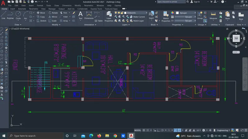
PROCEDURE FOR PLAN : Following steps are used for drawing of plan, elevation and section of building.
- Set units and limits as per requirement.
FOR PLAN:
Drawing external and internal wall:
- By using horzontal and vertical xline draw walls.
- Use Trim, Fillet, Offset tools for drawing of walls.
- Use 230 mm thickness for external wall and for internal wall 150 mm.
Drawing of Door and Window:
- For drawing of door and window make opening on wall.
- Make door using circle, rectangle and trim tool.
- Make window using pl, rectangle and trim tool.
- Move this to perfect position by using snap tools.
Drawing of furniture, kitchen blocks and bath and wc block:
- For adding this block command ADC.
- Drag the require blocks to autoCAD screen.
LAYER:
- After completion of drawing work, specify objects of building to different layer.
- Objects like wall, door, window, staircase, furniture, text, dimension, hatching and projection etc. are make layer with different colour.
- Use layer command, then specify colour, line weight and line type.
Text:
- From rebbon select text object then specify heigth of text then provide rotation angle of text.
For editing text used text edit command or double quick on text.
- According to requirement single and double text is used.
- For setting of text command ST and set diallog box.
Dimension:
- In this drawing, dimension line with dot end is used.
- Do dimensioning using dimlinear command.
- For continuning dimension from last point command dimcontinue.
- We we have to setting of dimension for changing of dimension unit, text and arrow setting command dst and enter.
- Diallog box open.
- After modifying dimension setting dont forget to quick on set current, otherwise before setting exists.
LEADERS:
- When we have to note information about specific object and there is no space near the object then leader is neccesary.
- When we require leader with more than 4 points then command qleader.
- Fill dialbox and enter.
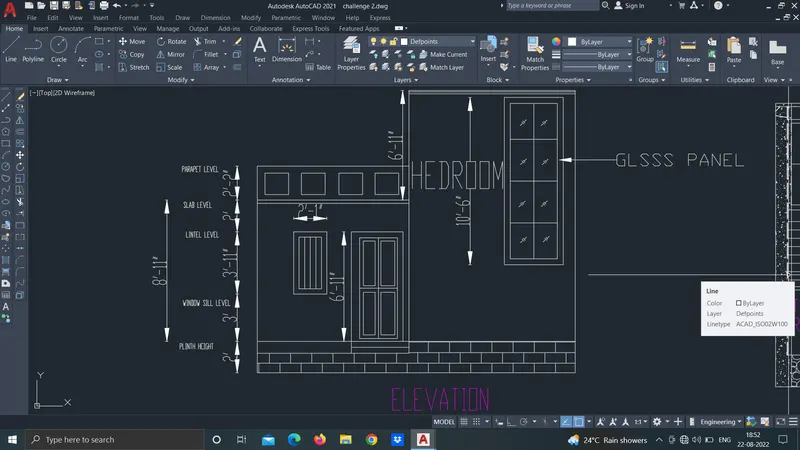
PROCEDURE FOR ELEVATION:
- After setting limits and units, draw external wall using xline.
- Atfter that mark the different height on elevation like window height, lintel height, slab height and plinth height.
- Take projection from plan of object which will show in elevation.
- Draw door, window, column, slab thickness, plinth details.
- Draw staircase, make sure rise will shown in elevation.
-All others instructions are same for drawing of elevation as that of plan as discussed above in detailed.
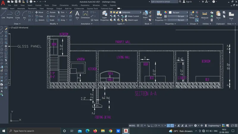
PROCEDURE FOR SECTION :
- Make sure the section line passing through plan is correct or not with related to section which is to be drawn.
- Taking projection from elevation plan, mark different levels.
- You have to imagine, how will object show after cutting from given section.
- Verify before drawn.
- Hatch the necessary objects.
- If you are able to draw plan and elevation then you automatically known how to draw section of building.
- All other instructions are same as that of plan and elevation as discussed above.
RESULT: After the completion of this 7 challenges and this project, I am able to draw structural drawings of buildings, plan, elevation and sections of building, footing details of building with great efficiency.