Project 1 _Creating an Architectural plan for the provided plot size and develop relevant basic structural drawings
AIM & INTRODUCTION
To create a floor plan with plot size 60'x20' and develop structural drawings in AutoCad
1. Architectural Drawing
-Floor Plan
-Elevations
-Sections
2. Structural Drawing
-Column layout
-Beam Layout
-Footing Plan
PROCEDURE
1. Architectural Drawings
- Open Autocad and open new drawing
- Drawing units are set to Engineering and '0-0.0" and Inches in the Drawing Style dialogue box.
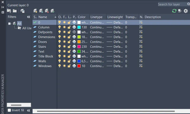
- Using Layer Properties Manager by giving LAYER command the required layers are created and given unique colours.
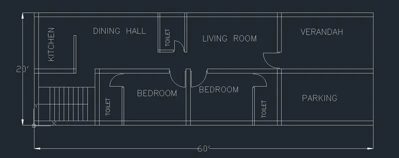
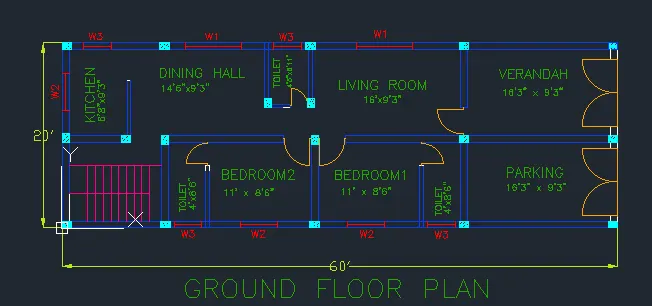
GROUND FLOOR PLAN
- XLINE command is given and vertical and horizontal construction lines are created.
- Using OFFSET command the outer walls of the building is created and the rest of the lines are trimmed off using TRIM.
- The inner walls, rooms are then created using OFFSET and TRIM commands.
- The current layer is changed to Stairs from Layers Panel in Ribbon.
- The stairs are created using LINE tool and the tread distance is taken as 10".
- The treads are offseted using OFFSET to create the stairs.
- The current layer is changed to Doors and windows from Layers Panel in Ribbon.
- The Doors and windows are inserted in the required areas using INSERT command.
- The sunshade is given loading ISO dash line from LINETYPE manager.
- The current layer is changed to Columns from Layers Panel in Ribbon.
- One column of size 1'x9" is created.
- It is then copied and placed wherever necessary using the COPY, MOVE, ROTATE commands.
- This Layout is copied and pasted in another location.
- Dimensions and text is set as current layer from Layers Panel in Ribbon.
- DIMSTYLE command is used to specify the dimension style, font, and size.
- DIMLINEAR command is used to create overall dimension.
- DIMCONTINUE command is used to create the rest of the dimensions.
- MTEXT command is given to create the text.
- It is copied and pasted in every room using COPY command.
- The text is then editted as required using Mtext edit by right clicking after selecting the text
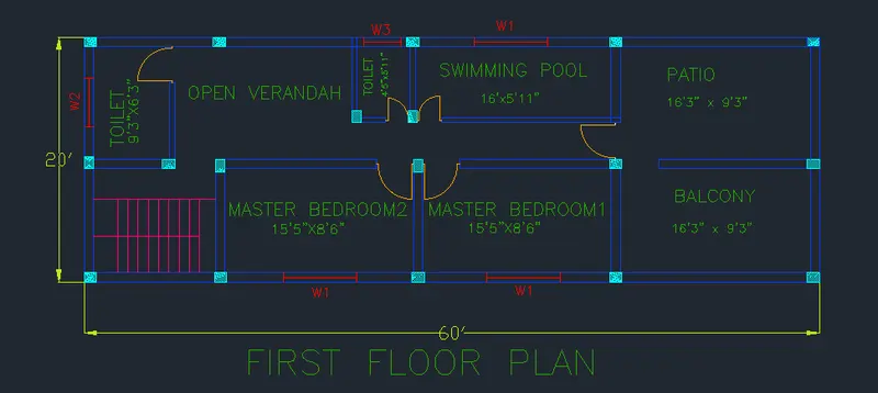
FIRST FLOOR PLAN
- The layout copied from the ground floor plan is edited as required using ERASE, TRIM commands.
- The Walls and slabs layer is set as current layer from Layers Panel in Ribbon.
- The required walls are created using LINE and OFFSET commands.
- The current layer is changed to Doors and windows from Layers Panel in Ribbon.
- The Doors and windows are inserted in the required areas using INSERT command.
FRONT ELEVATION
- The Ground floor plan is copied and pasted in another location using COPY.
- Then it is rotated using ROTATE command to 90 degrees.
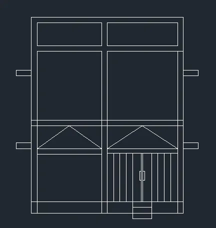
- Using XLINE command the projections of the sunshade, stairs, columns, doors and windows are made.
- The rest of the lines are trimmed off using TRIM.
- Parapet walls are created using LINE and OFFSET commands.
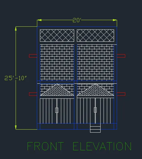
- HATCH command is given and BRSTONE hatch is used for the front wall.
- DIMLINEAR command is used to create overall dimension.
- DIMCONTINUE command is used to create the rest of the dimensions.
- The components are then selected and placed in their respective layers from the layer panel in the ribbon.
SECTION - A
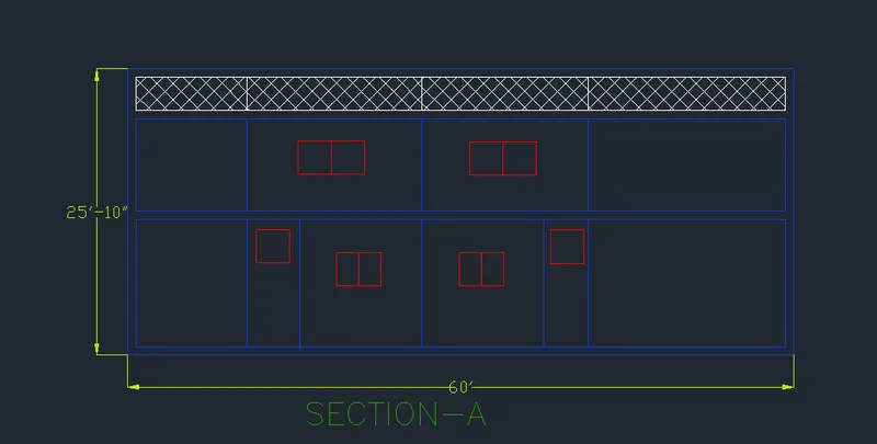
- The Ground floor plan and elevation drawing is copied and pasted in other locations using COPY.
- Using XLINE command the projections are made.
- The rest of the lines are trimmed off using TRIM.
- The components are then placed in their respective layers from the layer panel in the ribbon.
- Current layer is set to Dimensions and text from the layer panel in the ribbon.
- DIMLINEAR command is used to create overall dimension.
- DIMCONTINUE command is used to create the rest of the dimensions.
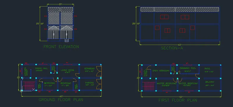
RESULT OF ARCHITECTURAL DRAWINGS
2. Structural Drawings
PROCEDURE
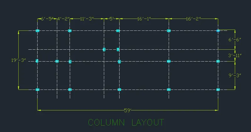
COLUMN LAYOUT
- The columns are then copied and pasted in another location using COPY command.
- Grid lines are drawn using XLINE command thorugh the middle of each column.
- The lines are selected and in properties menu the Linetype is changed to ISO dash.
- Dimensions and text is set as current layer from Layers Panel in Ribbon.
- DIMLINEAR command is used to create overall dimension.
- DIMCONTINUE command is used to create the rest of the dimensions.
- DTEXT command is given to create the text.
- It is copied and pasted in every room using COPY command.
- The text is then editted as required using by right clicking after selecting the text.
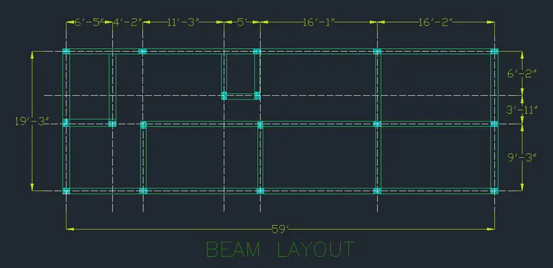
BEAM LAYOUT
- The beams are drawn using LINE and OFFSET commands.
- The rest of the lines are trimmed off using TRIM command.
- Dimensions and text is set as current layer from Layers Panel in Ribbon.
- DIMLINEAR command is used to create overall dimension.
- DIMCONTINUE command is used to create the rest of the dimensions.
- DTEXT command is given to create the text.
- It is copied and pasted in every room using COPY command.
- The text is then editted as required using by right clicking after selecting the text
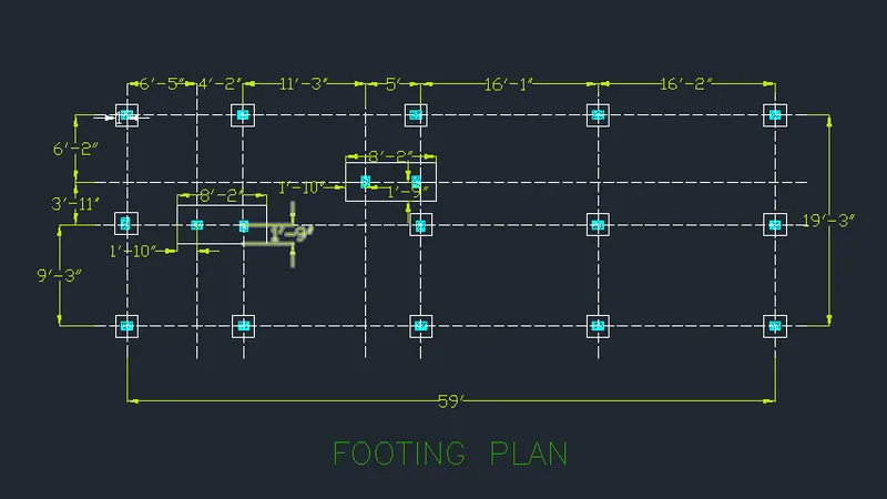
FOOTING PLAN
- The remaining columns and grid lines are copied and pasted to a new location using COPY.
- Dimensions and text is set as current layer from Layers Panel in Ribbon.
- DIMLINEAR command is used to create overall dimension.
- DIMCONTINUE command is used to create the rest of the dimensions.
- DTEXT command is given to create the text.
- It is copied and pasted in every room using COPY command.
- The text is then editted as required using by right clicking after selecting the text.
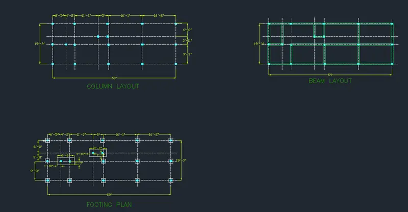
RESULT FOR STRUCTURAL DRAWINGS
RESULT
Thus the plan with the plot size 60'x20' is plotted and the architural drawings and structural drawings are drawn in AutoCad
The plan,sections and elevation are drawn
The column layout,beam layout and footing plan are drawn