Project 1 _Creating an Architectural plan for the provided plot size and develop relevant basic structural drawings
PROJECT 1
Creating an Architectural plan for the provided plot size and develop relevant basic structural drawings.
QUE:
Design and Draft a layout of a residential building with the following details:
a. Plot Size: 60’x20’(18.3m x6m)
b. Orientation- Facing East
c. Develop the following: 1. Architectural Drawing (Floor Plan, Elevations, and Sections) 2. Structural Drawing (Column, Bean, Footing Plan)
Aim: To draw residential building of dimensions 55’X60’ with following drawings
a) Plot drawing
b) Ground Floor Plan
c) First Floor Plan
d) Elevation
e) Center line drawing
f) Footing Layout
g) Beam Layout
h) Section View
INTRODUCTION:
The residential building to be drawn with plot dimensions 55’X60’. The plinth dimensions are chosen as 35’X40’. The G+1 floor is designed as duplex house with stairs inside the house. The plot is north facing. The building is designed with following rooms
- Ground Floor Living Room
- Kitchen
- Main Bedroom
- Puja Room
- Staircase to first floor
- First Floor Living room
- Bedroom-2
- Guest Bedroom
- Balcony
- Staircase to roof
Building is designed with main door at the North-East (Ishan) facing north and main gate at north west position. Initially layers are created for all the components of the house.
The dimensions of the components of house are as follows
Walls
1) Thickness of main walls is taken as 9”
2) Internal wall thickness is taken as 4.5”
Columns and Beams
1) All the columns are of size 9”X12” or 12”X9” respectively
2) All the beams are of size 9”X9”
3) Rebar specifications are explained in procedure
Doors
There are three door types
1) Dimension of Main door and entrance 4’X8’ and at the balcony access
2) Dimension of doors of all bedrooms are 3’6”X7’
3) Dimension of doors of all toilets and Puja room are 2’8”X7’
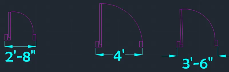
D3: 2’8”-wide (Small Door)
Windows
1) Windows to the side of main door are taken as 2’7.5”X4’5”
2) Windows in main bedrooms and in both halls 3’X5’6”
3) Windows over the bed lights as 1’6”X4’6” in all bedrooms
4) Ventilators as 1’6”XN depending on its preferred height

Add windows at the stairway and both side of the main door each of 2’7” and top right wall edge corner
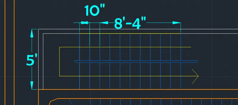
Staircase
a) Inner Staircase consist of 21 steps with curved steps at the change in flight direction making it single flight straircase
b) Thread and Raiser are taken as 10” and 6” respectively
c) Curve radius is also taken as 10”
d) Outer staircase is connected to the roof with 21 steps
e) Thread and Raiser are taken as 10” and 6” respectively
f) Hand rails are 2” in diameter and height of 2’9”
Compound wall
a) Height of compound wall is taken as 6’
b) Thickness of compound wall is similar to wall thickness i.e. 9”
PROCEDURE:
Open AutoCAD
In Start-up settings start from scratch select Imperial (Feet and Inches)
Open grid and snap settings
- Change snap and grid spacing to 1’
- Change major line every grid line to 10
- Turnoff adaptive grid
Type ‘un’ in command box and press enter
Change units’ type to decimal and precision to 1’1/16” and insertion scale to inches
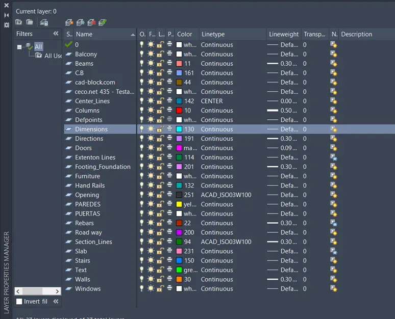
Step 1: Creating Layers
Open Layer properties and create new layers by clicking on new layer or right click on any layer and select new layer to create new layer
Layers are created as follows
Step 2: Creating Plot Drawing
Initially direction mark is made drawing perpendicular lines and adding text and respective layer is assigned
Change the current layer to wall layer
- Draw a rectangle of dimensions 60’X54’9.625” at any point on the screen
- Draw a line vertically up from top left corner of distance 21’
- Offset the left and bottom line of rectangle drawn to distance of 2’ right and up respectively
- Offset the top line of rectangle drawn to distance of 18’ to downwards
- Offset the right edge line of rectangle drawn to distance of 18’ to downwards
- Trim off the extra portions of inner rectangle
- Draw the roadway of width 15’ along with center alignment line
- Add relative text to the plot drawing
- Hatch the plinth area using hatch type ANS137 and hatch scale 100
Step 3: Creating Ground Floor Plan View
A. Creating Walls
Change the current layer to walls layer
- Draw a rectangle of dimensions 60’X54’9.625” at any point on the screen
- Offset the left and bottom line of rectangle drawn to distance of 2’ right and up respectively
- Offset the top line of rectangle drawn to distance of 18’ to downwards
- Offset the right edge line of rectangle drawn to distance of 18’ to downwards
- Trim off the extra portions of inner rectangle
- Offset both rectangle to a distance of 9” to inside to give the wall thickness
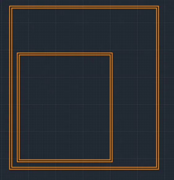
- Draw the inner walls of thickness 4.5”
- Offset the bottom inner wall edge to a distance of 12’
- Offset the last offset line to a distance of 4.5”
- Offset the last offset line to a distance of 4’7.5”
- Offset the last offset line to a distance of 4.5”
- Offset the left inner wall edge to a distance of 14’
- Offset the last offset line to a distance of 4.5”
- Offset the last offset line to a distance of 4.5”
- Offset the last offset line to a distance of 4’3”
- Offset the last offset line to a distance of 4.5”
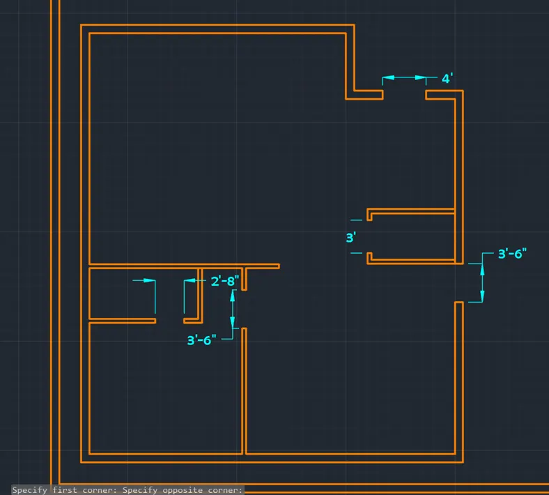
- Trim off the extra lines to obtain the figure as shown below
Create the front door inside the top right corner as shown in below figure
Create the main door opening of the dimension 4’
. Drawing the plot, and giving setback.Given plot size as 18.3m x6m.Mark the direction N, S, E, W. By rectangle, draw the plot giving dimensions as 6 and 18.3 m.
3. Next give setback from the plot, 4.3m and 3m for the sides.The proposed building should come inside the setback drawn.
4. Drawing wallOffset 0.25 m from the boundary after the setback is taken for the wall thickness.
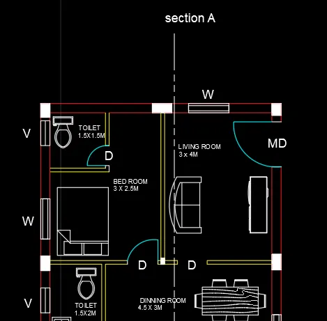
5. As the orientation is given as East, main door should face East.For living room, give 3m offset horizontally from the West side and size of the room will be 3 x 4 m.
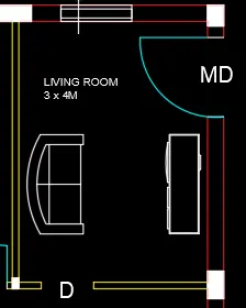
6. As per Vaastu Shastra, North-East is favourable for living room and the entrance should face North or East.
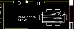
7. Same the dining room Again offset 3m from the living wall for dining room.Width will be 4.5m
8. Offset 2m horizontally from dinning wall and 4m vertically.The size of kitchen is 2 x4 m.Trim 1 m for the door opening. According to Vaastu Shastra the ideal position for kitchen is South-East ,with cooking place facing East.
9. Drawing Master bedroom and toilet From the South wall offset 4m and width of 4m joining the kitchen wall.
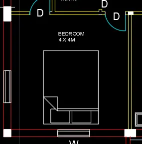
10. The size of bedroom is 4x 4m.Create opening of 0.80 m by offset and trim commands.
For toilet, draw an offset horizontal of 1.5 m from the Dinining wall and Size of toilet is 1.5 x2m.
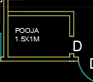
11. Drawing of Puja room From the Toilet offset 1.5m and from master bed room offset 1m and Size of the puja room is 1.5m x1.0m as per North-East should be good for puja room according to Vaastu Shastra
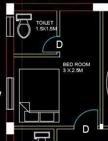
12. Drawing of Bed room with toilet From Living room offset 3m and from dining room offset 2.5m .Size of the bed room is 3m x 2.5m and Draw a toilet of 1.5m x 1.5m inside the bed room.
13. With multiline text, draw the text box, text height as 0.15m and style as Times roman.
14. Place the doors and windows in the respective places.
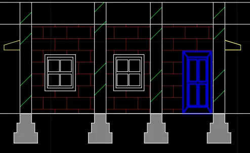
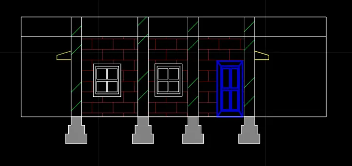
15. Elevation part the Projecting lines to draw the elevation.Project the wall lines to the top.
16. Draw a horizontal line.Offset 1 m for the plinth level.Offset 2.1m for the Lintel level.Offset 3.5m for the floor level .Offset 0.6m for the parapet wall .
17. Trim off the extension lines and make shutters and panels for doors and windows.For architectural purpose, create some hatches.
18. Project the lines from the elevation for the height and from the section line of plan for the horizontal members. Drawing windows, doors and stairs in section.
19. Using hatch hatch the walls with the bricks hatch and foundation with the concrete hatch.
20. Project the lines from the elevation for the height and from the section line of plan for the horizontal members.
21. Drawing windows, doors and stairs in section.Draw the window and door which we see after cutting the section line.
22. Using hatch hatch the walls with the bricks hatch and foundation with the concrete hatch.
Place the windows and foundations in the respective layers and give colours.
Structural drawings:
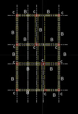
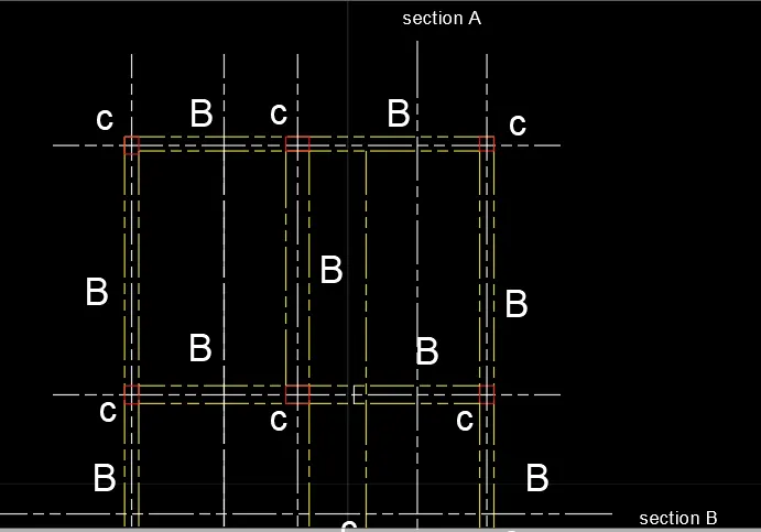
1. Column layout : Column of size 0.25m x0.25m is considered.Columns are placed in all corners of the wall and intersection of walls wherever required.

2. Now draw the centre line for column from the annotate tab -centre line and mark the grid line as 1,2 in the y direction and A, B, C, D, E, F in the x direction.
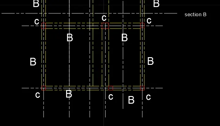
3. Footing Layout: Isolated footing of size 0.5m x0.5m is provided.Create a rectangle with dimension 0.5x0.5 m, place the centre of rectangle with the centre of column.
4. Drawing of plinth beam connect the columns by beam of width 0.25m, as the wall thickness is 0.25.Plinth beam is provided below all the walls.
5. Create a layer for beam and put the plinth beam in that layer.
RESULTS: Architectural and structural plan of a residential building is drawn
ELEVATION DRAWING
STRUCTURAL PLAN
Leave a com