Drafting of various geometries using Chamfer, Fillet tool in AutoCad
AIM: To draw the geometries using Chamfer, fillet tool in Autocad.
Commands used: Line, circle, chamfer, fillet, mirror, trim, move, rotate, annotate.
Procedure:
DRAWING 1:
a) Open new file and set decimal and precision to 0.00.
b) Command line: From random point draw 3.00 m line and @2.12<45, @2.83<135 then 2.00m line and close.
c) Command offset:Offset 3.00m line to 1.00m and 2.50m.
d) Command circle:From midpoint of 3.00m line at 2.50m and 1.0Om draw a circle of diameter of 1.20 at 1.00m and 0.80 at 2.50m.
e) Command erase:Erase the offsets.
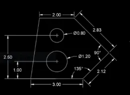
DRAWING 2:
a) Select architectural and polar tracking for angles 15,30,45,60 and so on.
b) Command line: Draw a horizontal line and draw 2'6'' line at 225 degrees, 3' line perpendicular to it, 2'5'' vertical line and 8' horizontal line, 1'9'' vertical line and 2'10'' @225 degrees and close.
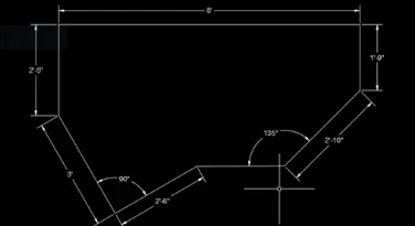
DRAWING 3:
a) Open new file and set engineering and precision to 0'-0.0"
b) Command line: 2'-6.5" in -ve X-axis, 3-3" in -ve Y-axis, 5-0.1" in +ve X-axis, 1-6.0" in +ve Y-axis and close.
c) Command offset: offset 3'-3" line at a distanceof 1'-3.0" and 5'-0.1" at a distance of 1'-6.0"
d) Command circle: draw a circle of diameter of 1'-6.0" from the centre of offsetted lines.
e) Command erase: Erase the offsets.
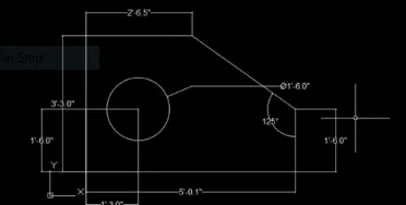
DRAWING 4:
a) New page and select decimals with precision 0.00 while keeping ortho on.
b) Command line:Draw 3.00m line in +ve X axis
3.0.50 In -ve Y axis, 2.50m in +ve X axis, 2.50m in +ve Y axis, 2.00m in -ve X axis, 3.00m in +ve Y axis, 2.50m in -ve X axis, 2.00m in -ve Y axis, 3.00m in -ve Y axis and close.
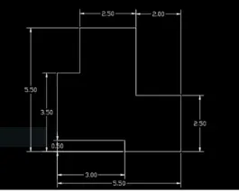
DRAWING 5:
a) New page select decimal and precision 0.00 while keeping ortho on.
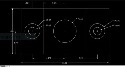
b) Command line: 6.00m vertical. 11.50m horizontal and 6.00m vertical and 11.50m horizontal.
c) In object snap setting keep midpoint, centre, intersection and geometric centre on.
d) Command Circle: Draw circle at the centre with diameter 3.00m
e) Command offset: offset 6.00m line at a distance of 3.00m on both sides and offset the 11.50m line at adistance of 3.00m.
f) Command circle: Draw concentric circles at the intersection of the offsetted line of diameter 1.00m and 2.00m on both sides.
g) Command erase: Erase the offsets.
DRAWING 6:
1.New page select decimal with precision 0.0.
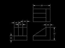
2.Command line:1.Sm horizontal and 1.5m vertical on both sides.
3.Command offset offset 1.5m line to 0.5m.
4.Command divide: Divide 1.5m line into 3 segments.
5.Command line-: Join the divided lines.
6.In object snap setting keep the Extension On
7.C0mrmand line: Draw 2.0m line and 1.5m line and O.5m horizontal on top and ln vertical and 1.5m horizontal and O.5m vertical and join the slant line.
8.Command line:2.0m horizontal and 1.5m vertical on both sides.
9.Command offset: offset 1.5m line to O.5m.
10.Command divide: Divide 1.5m line into 3 segments.
11.Command line: Join the divided lines.
DRAWING 7:
a) New page and set decimal and precision to 0
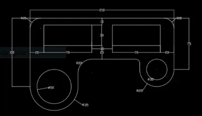
b) Command line: Drawing 210m horizontal line and 100m vertical line on left side and 75m vertical line on right side, since arc has radius of 35m drawing a line of 70m on left side and has a radius of 25m drawing a line of 5Om on right side.
c) Command Arc: From start, end and radius draw an arc of radius 35m on right side and an arc of radius 25m on leh side.
d) Command Circle: From midpoint of 70m line on left side draw a cirle of diameter of 5Om and 30m on right side.
e) Command offset Offset 210m line at a distance of 60m.
f) Command fillet:Filleting to radius 15m on top right and left and radius of 20m on inner left and radius of 6m on inner right.
g) Command offset:offsetting 210m line to !Om and 100m and 75m line to 20m.
h) Command rectangle·:70m length and width of 30m from off setted line on both sides.
i) Command erase: Erasing the otfsetted line and unwanted lines.
DRAWING 8:
a) New page set decimal and precision to 0.00
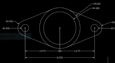
b) Command cirde:Draw concentric circles of diameter 5.00m and 4.00m
c) Command line: From the centre point of circle draw 4.275m line on both sides.
d) Command circle: Drawing a circle of diameter 0.90m on both sides.
e) Command arc: from start, end and radius draw an arc of radius 0. 90 on both sides
f) Command line: Join the lines to the arc.
DRAWING 9:
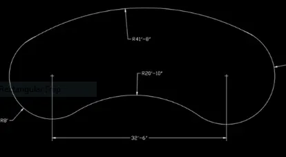
a) New page and set Engineering and precision to 0'-0"
b) Command Line: Draw a 32'-6'' horizontal line.
c) Command circle:Draw a circle of radius 8' on left side of line and radius of 9' on right side of line.
d) Command Arc: From start, end and radius drawing a arc of 41'-8" on top and 20'10" on bottom.
e) Command trim: trim the unwanted line and curves.
DRAWING 10:
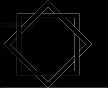
a) Command rectangle: Draw a rectangte of same length and same width of one smaller size and another slightly bigger one from common centre.
b) Command Rotate: Rotating the drawn squares by 45 degree keeping the copy
c) Command trim:Trim the crossing lines according to the figure.
DRAWING 11:
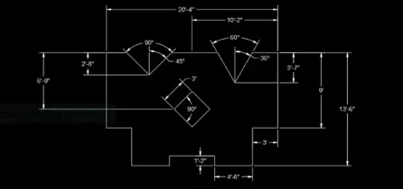
a) New page and set engineering and precision 0'0"
b) Command line: Draw 10' -2" horizontal line, 9' vertical line, 3' horizontal line,4'-6" vertical and horizontal line and 1'-2" vertical line.
c) Command mirror: Mirror the above lines at centre axis.
d) Command offset: offset the 20'-4" to a distance of 6'-9" arnd 13'-6'' to a distance of 10'-2".
e) Command Rectangle: Draw a rectangle of length and width 3' from the centre point of off setted line.
f) Command Move: moving the centre of rectangle to the centre of offsetted line.
g) Command rotate: Rotating the Rectangle by 45 degrees
h) Command offset: Offsetting 20'-4" to a distance of 2'-8" with polar tracking on draw an angle of 90 degrees. Offset 20'-4" to a distance of 3'-7' with polar tracking on draw an angle of 60 degrees.
i) Command erase: Erase the unwanted lines.
RESULT: The given drawings have been drawn using autocad.