Project 1 _Creating an Architectural plan for the provided plot size and develop relevant basic structural drawings
Introduction: Autocad is a commercial Computer Aided Design(CAD), It is marked and developed as Autodesk. It was first released on december 1982. Autocad derived from a program, which was beganed in 1977 and then released in 1979 called as Interact CAD, and also called in early documents od autocad as microCAD, Auto desk cofounder was Michael Riddle.
The first version of cad was released in december 1982 and was supported on CP/M-80 computers, By march 1986 Aotocad has became most uniquitous cad program worldwide. The file format of autocad was .dwg, and its interchange file format to DXF, have become a standard. Autocad was included support for .dwf, a format developed and promoted by Autodesk, for publishing CAD date. In year 2022 the Autocad 36th major version was released and the 12th consecutive year of Autocad foe Mac.
CAD is a technology which replaces manual drawing with automated process, if you are a drafter, desingner, architect or engineer you have been used 2D or 3D CAD programs i.e., Autocad or Autocad LT software. Autocad helps you in draft construction documentation, explore ideas for design, viaualise concepts through photorealistic renderings and gives how a design performs in real world.
Autocad mailnly used by industries, architects, engineers, city planners, project managers, graphic designers and other professionals.
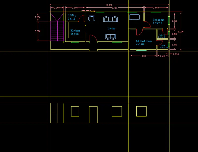
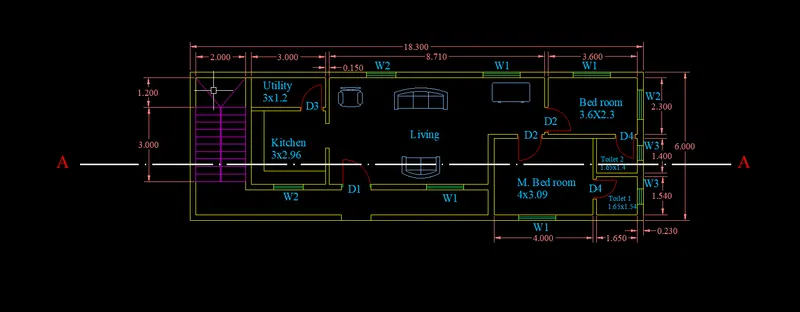
AIM: To create Architectural plan of a Residential building of plot size 60'X20' or 18.3mX6m Facing East, sectional drawing, elevation, and Structural drawings column, beams and footing layout
Steps:
1. Type units command and select decimal and meters, and set limits from (0,0) to (100,100)
2. First create Layers, by going to layers in layer properties and create new layers as
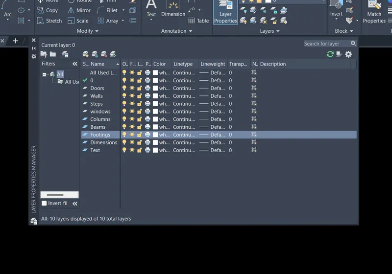
3. Set the current layer as Walls and Draw one vertical and horizontal line using Xline command.
The thickness of external walls is taken as 0.230m and internal wall is 0.150m
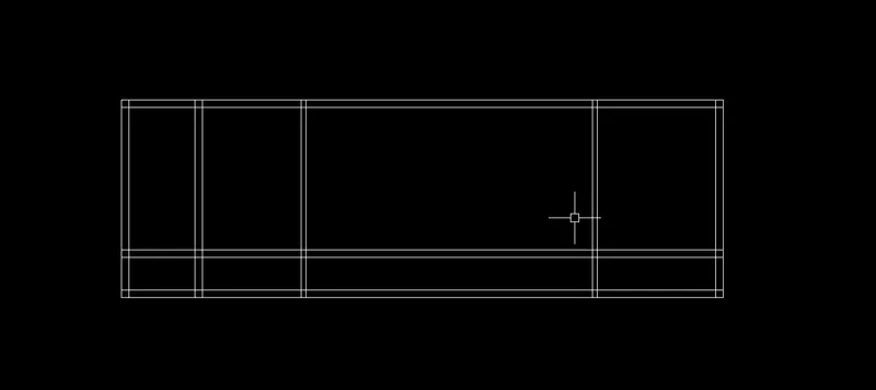
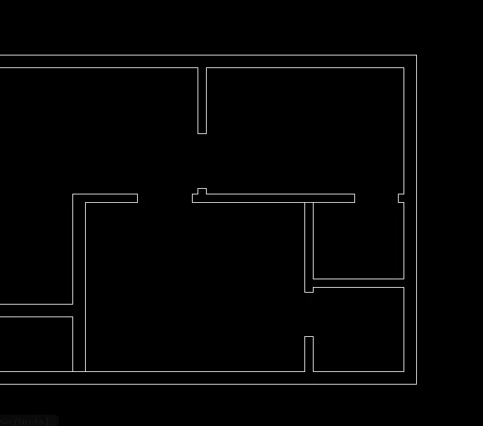
Use Offset command and offset the vertical line in right direction by 0.23, 2, 0.23, 3, 0.15, 8.71, 0.15, 3.6, 0.23
Use Offset command and offset the horizontal line in upward direction by 0.23, 1, 0.23, 4.31, 0.23
Trim all the extra lines then we get,
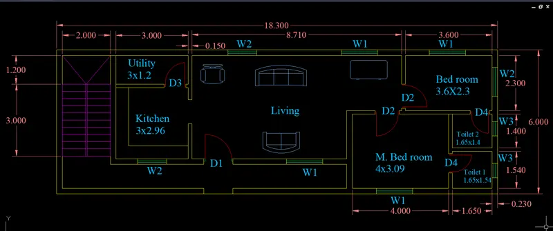
4. To create Utility ann Kitchen, Offset the top horizontal line in downward direction by 1.2, 0.15m
And create a door D3 from kitchen to utility width is 0.9m, and the Opening door from Hall to kitchen is D2 width is 1m
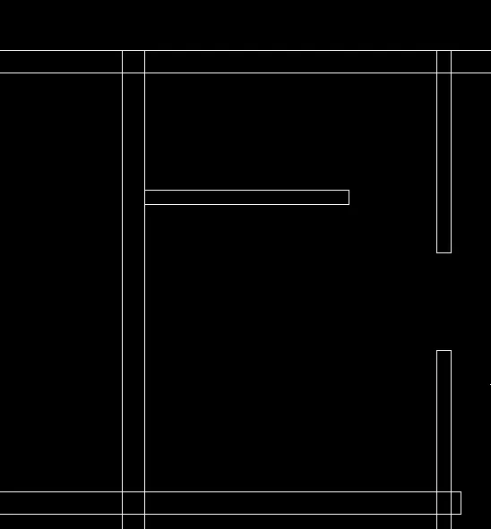
5. To create Master bedroom of size 4X3.09m and Guestbedroom of size 3.6X2.3m
And Toilet 1, attached to master room has size 1.65X1.54
And Toilet 2, attached to guest bed room has size 1.65X1.4
First the top inner horizontal line in offsetted inward direction by 2.3,0.15,1.4,0.15 and trim the extra lines
Now use Breakatpoint and break the right inner vertical line at 2.3 from top and offset that line to 1.65,0.15, 4, 0.23. And trim all the extra lines.
The Door D2 of width 1m is kept for two bedrooms
The door D4 width 0.8m is kept for both toilets
6.Door D1 of width 1.2m is kept for Hall at an offset of 0.5m from kitchen
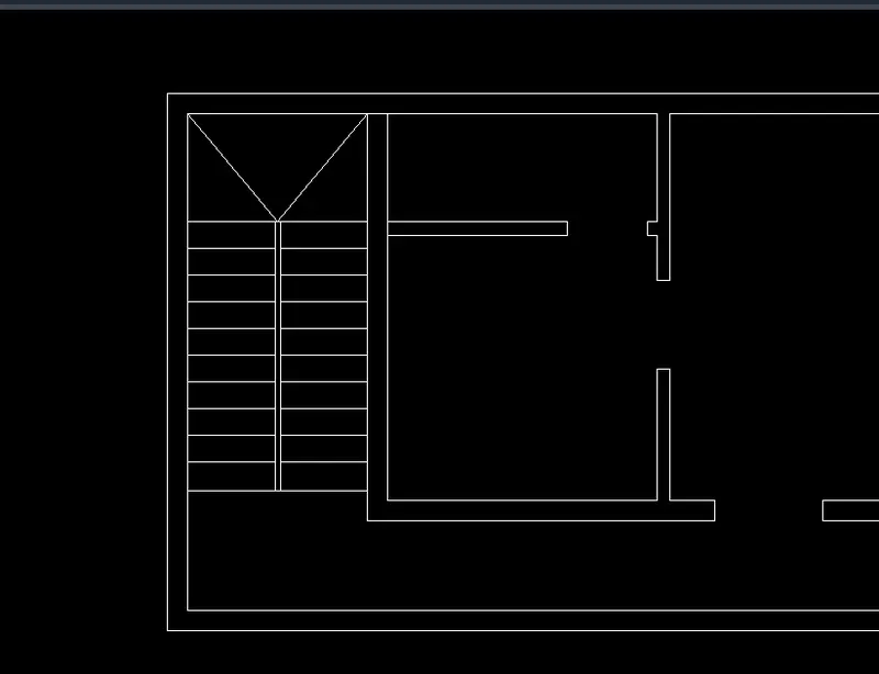
To create Stairs, Set the Current layer as Stairs
Provide step width= 1m, Thread= 0.3m and rise=0.15m
Offset the top inner horizontal line by 1.2m and then by 0.3, then Copy and use Array for 10 numbers at placed it at a distance of 0.3
Trim and remove all the Extra lines.
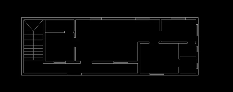
7. The windows taken sizes are, and change the layer to Windows
W1=1.5m
W2= 1.2m
W3=0.6m
For kitchen window is W2 and is placed at 0.9m from left vertical wall use offset and trim command
For Hall, W1 window is placed at a distance od 1m from master bedroom , and on top horizontal wall W1 is placed at 1m from guest bed room
on top horizontal wall of hall W2 is placed at a distance of 1.5 from left vertical wall
For guest bedroom, W1 is placed on top horizontal wall at a distance of 1m from hall and W2 is placed on right vertical wall at a distance of 0.5 from horizontal
For Toilets W3 window is provided at adistance of 0.5m from the common wall of both toilets.
Trim all the extra lines.
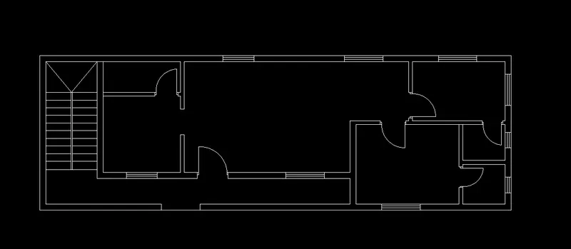
8. Change, Set current layer as Doors and place droors
D1 width= 1.2m provided at main entarance
D2 width= 1m provided for two bed rooms and opening for kitchen
D3 width= 0.9m provided for utility
D4 width= 0.8m for two toilets
9. Change the colours of the different layers as you like and then
Set current layer as Dimensions and measure dimensions
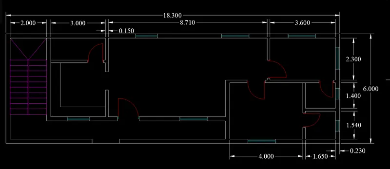
10. Set current layer as Text, Provide the text using Mtext and use Times New Roman Greek font style and height of Font is 0.4
Type DC and keep the furniture you wanted
Change the colours as you like
Elevation:
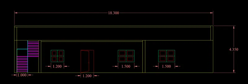
1. To draw elevation, Setcurrent layer as walls and draw XLines from the plan vertically
and take horizontal Xline and Offset upward direction by 3, 1.35
height of the floor is 3m
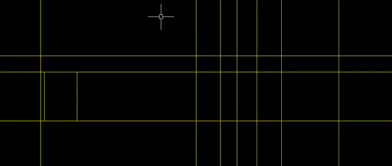
2. Window W1 size is taken as 1.5X1.1m and placed at 1m from bottom
W1 is at bedroom and living room
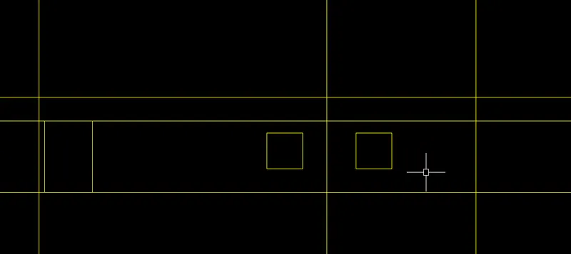
3. Xline lines are drawn from door and W2 window of kitchen
W2 size is 1.2X1.1 and placed at 1m from bottom
Door size is 1.2X2.1 is placed
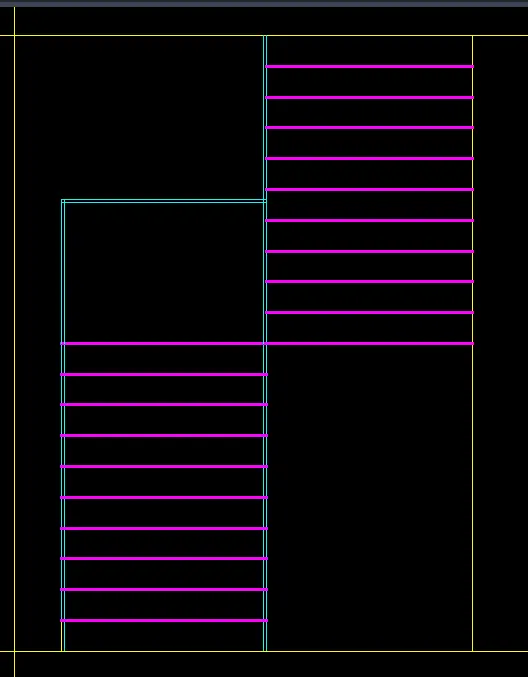
4. Change the current layer to Stairs and place the steps at a rise of 0.15m
The green colour represents hand rails
the step size is 1mX0.3X0.15
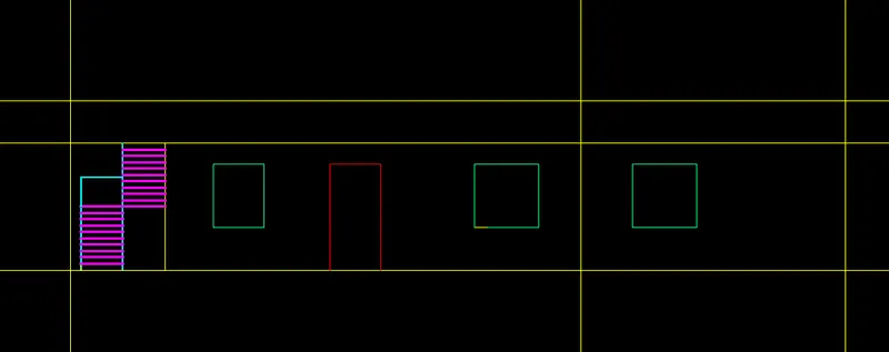
5. Select the windows and go to properties and change the layer as windows
similarly select door and change the layer as doors
6.The floor height provided is 3m and parapet wall height is 1.2m
Delete all the Xlines and trim all the extra lines
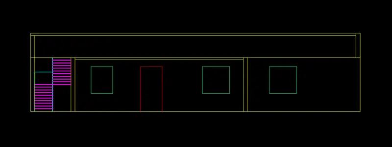
7.Set current layer as dimension and measure dimensions and edit where required
Section:
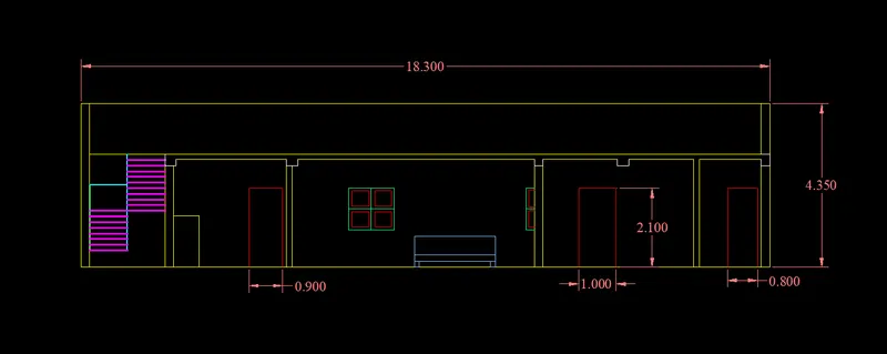
1. Consider section A-A as shown in the below figure
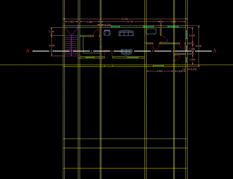
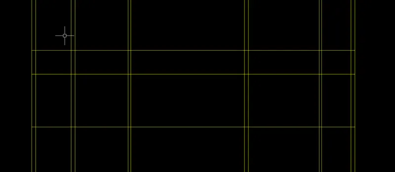
`2.Draw the Xlines from the plan and and draw the hrizontal line and offset it upward by 3,1.35
3. The doors for Toilet 1 and master bedroom can be seen when we cut A-A section
First Set the current layer as Door and draw
the toilet has door D4 size 0.8X2.1
the bedroom has door D2 of size 1x2.1
Trim the Xlines
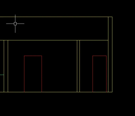
4. Set current layer as window and draw W2 of size 1.2X1.1 at 1m from bottom
and a part of W1 can be seen so w1 size 1.5x1.1 by using xlines draw w1
Set the current layer as Door and draw the utility door of size 0.9X2.1m
Place the front view of soft, drawn by using line and rectangle command
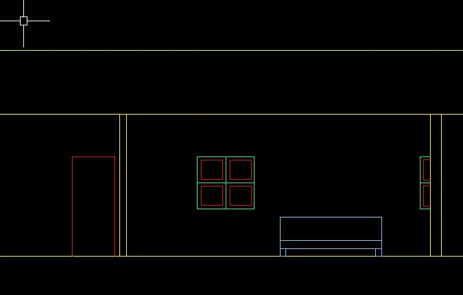
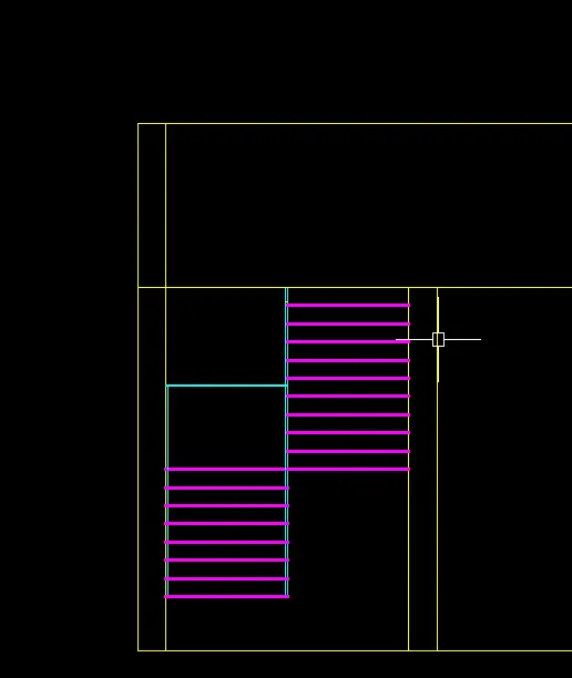
5. Set the current layer as stairs,
now as the section passes after the second step, we cant see the first two steps so draw without twosteps.
place the steps at a rise of 0.15m
The green colour represents hand rails
the step size is 1mX0.3X0.15
6. Set the current layer as dimensions and measure dimensions
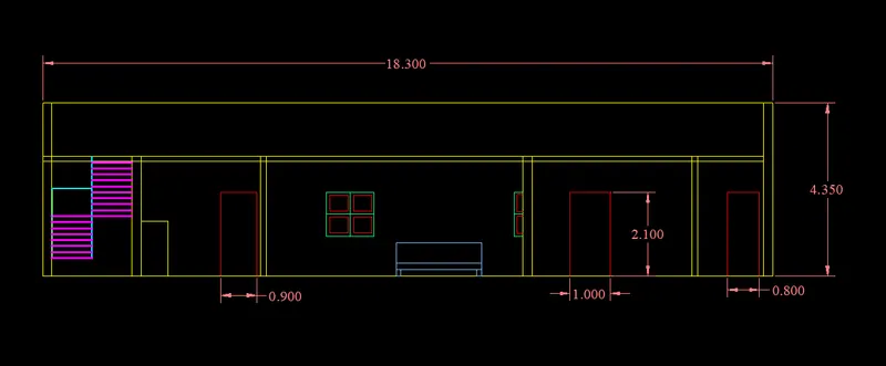
7. Provide the slab thickness as 0.125
and change the current layer as beams and provide beams
the crosssection of right most beam is 0.23X0.3
The second beam from right has cross section 0.3X0.3 and the mid of beam is a distance of 3.905 from outer right vertical wall
the crosssection of left master bed room beam is 0.23X0.3
the crosssection of Kitchen beams are 0.3X0.3
Trim the extra lines
Structural drawings:
Columns:
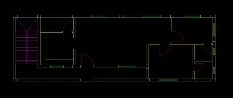
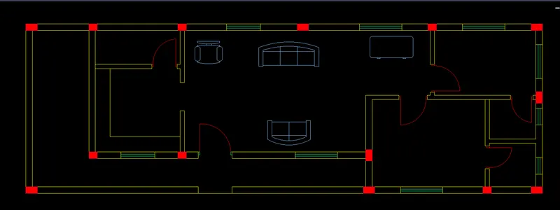
1.First Set the current layer as columns and hide the dimension and text layer
Column size of 0.4X0.23 is placed on top and bottom corners on left
And column size of 0.3X0.23 is placed at the corners of Kitchen and utility
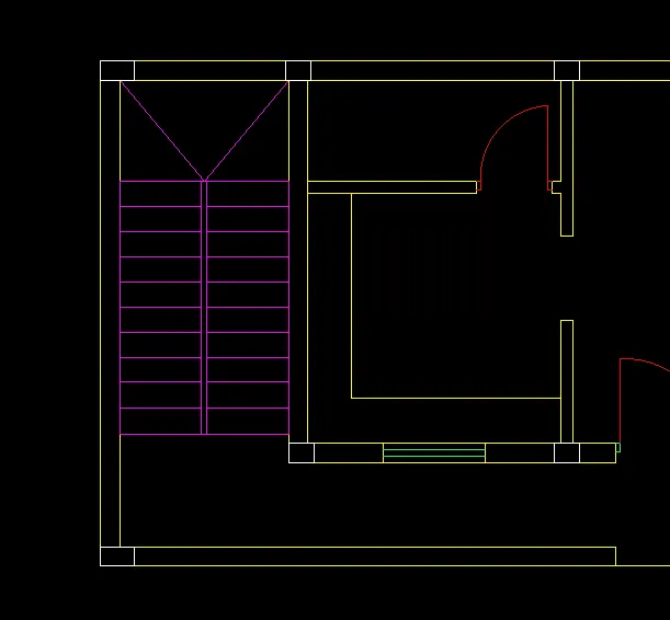
2. Place a column of size 0.4X0.23 from 4m of living room left inner vertical wall
and a place a column 0.4x0.23 on bottom left corner of master bedroom
column size 0.23X0.4 is placed at junction of living and master bedroom
Column size 0.3X0.23 placed at the top left corner of guest bedroom
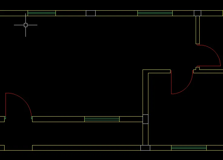
3.Column size of 0.4X0.23 is placed on top and bottom corners on right vertical wall
column size 0.4x0.23 placed at right bottom corner of guest bedroom
column size 0.3x0.23 placed at right bottom corner of master bedroom
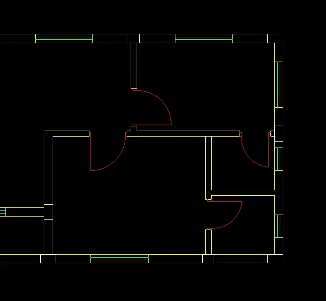
4. Total column layout
5.Provide hatch inside the column with red colour
Column layout:
1. Hide all the layers, only on columns and join all the columns at coners by drawing mid of external wall thickness
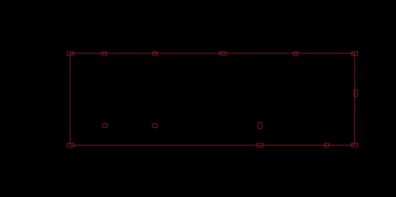
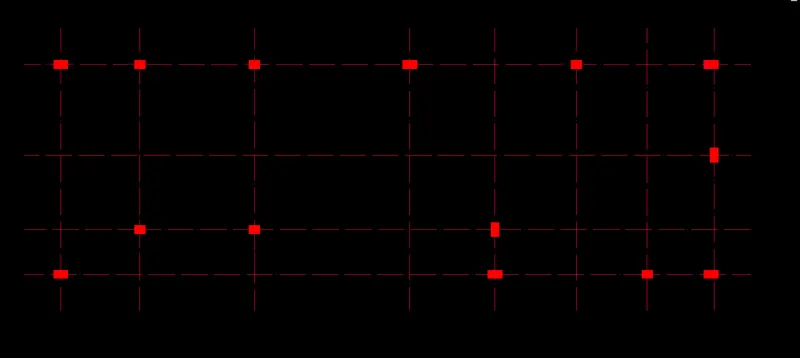
2. Draw the lines using Line command from the center points and extend the lines and join

3. Make all the lines ad dash lines and hatch columns
Beam layout:
1..First Set the current layer as Beams
Take column layout and draw
The beam cross section of 0.4X0.3 is provided at the left ,
The beam cross section of 0.3X0.3 is provided for utility and kitchen
The bottom and top beams as cross section 0.23x0.3
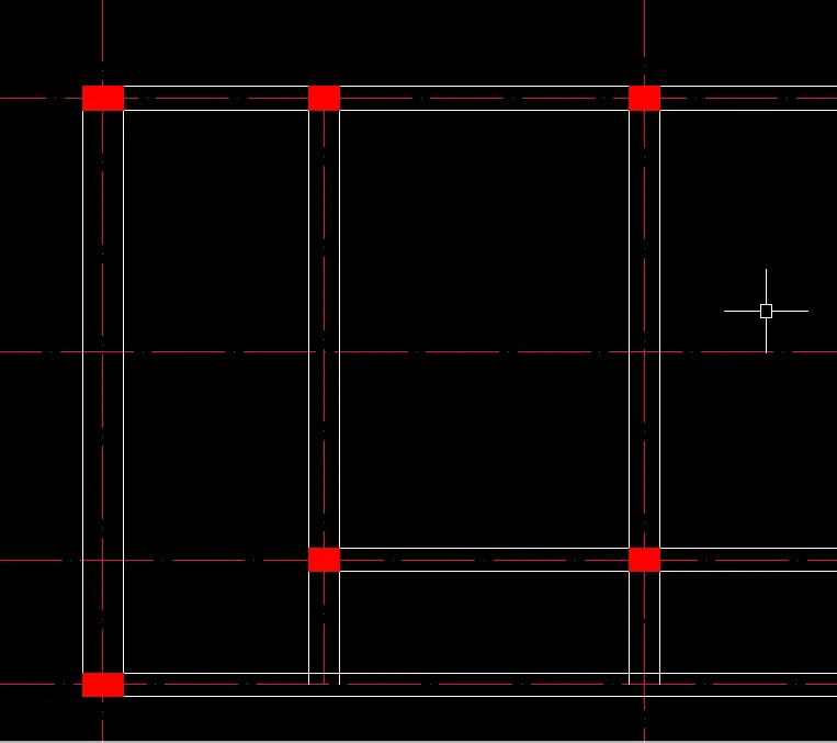
2. The beam cross section of 0.23X0.3 is provided for top and bottom horizontal and right vertical beam
The beam crossing master bedroom column is 0.23X0.3
The beam cross section of 0.3X0.3 is provided for guest bedroom that connects to beam
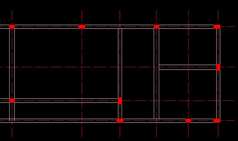
3.
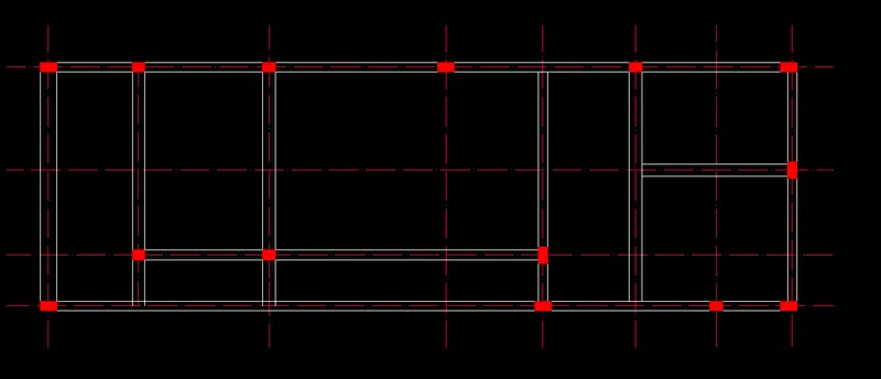
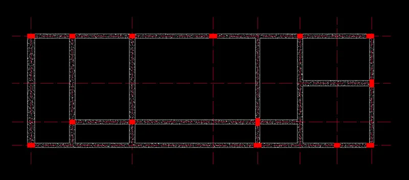
4. Join beam from master bedroom left upper column beam to next beam and
using hatch command, hatch the beams with concrete
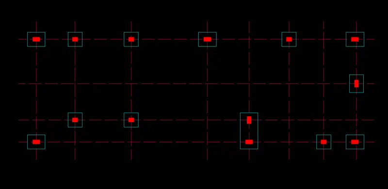
Footing layout:
1..First Set the current layer as footings
Take column layout
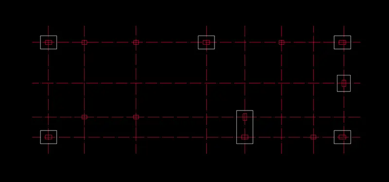
A footing size of 1X0.8m is placed for columns of size 0.4X0.23
A footing size of 0.8X1 is placed for columns of size 0.23X0.4
Combined footing is provided at masterbedroom of size 1X2.03m and the column sizes are 0.4X0.23 and 0.23X0.4
2. A footing size of 0.8X0.8m is placed for columns of size 0.3X0.23
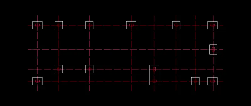
3. Provide hatches for columns and change the colour of footing by going to layer properties