Project 1 _Creating an Architectural plan for the provided plot size and develop relevant basic structural drawings
To Create an Architectural plan for the provided plot size and develop relevant basic structural drawings
Introduction and Prerequisite :
- Open autocad application
- Type Qnew and open new drawing
- Set units according to drawing
- Switch on object snap and object snap modes : Endpoint, Midpoint, Center, Nearest, Intersection, Perpendicular and Node
- Ortho mode is ON
- Using autocad G+1 east facing residential building is created
Procedure :
- Set units to decimal, precision zero and units to scale as "m"
- Procedure for dimensions setting : Enter command dimstyle
Click on new and create a new style "STYLE 1"
1. Now go to Lines section and set the following:
Color, linetype and lineweight remians "ByBlock"
Extend beyong dimlines as 0.18
Offset from origin as 0.0625
2. Next go to symbols and arrow section and set the following:
Arrow size 0.18
3. Next go to Text and set the following:
Text style : Standard : Font style - Arial, Font name regular
Text color : Byblock
Text height : 0.18
Text placement both vertical and horizontal as centered, View direction as left to right
Offset from dimline : 1
Text aligment : Horizontal
4. Next go to Fit and set the following:
Use overall scale of 1
5. Next go to Primary units and set the following:
Unit format : Decimal
Precision : 0.00
Press okay and click on set current
Press close - Text font is arial and text height is taken as 0.2
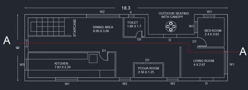
- In this plan internal wall thickness is taken as 0.1m and external wall thickness is taken as 0.3m
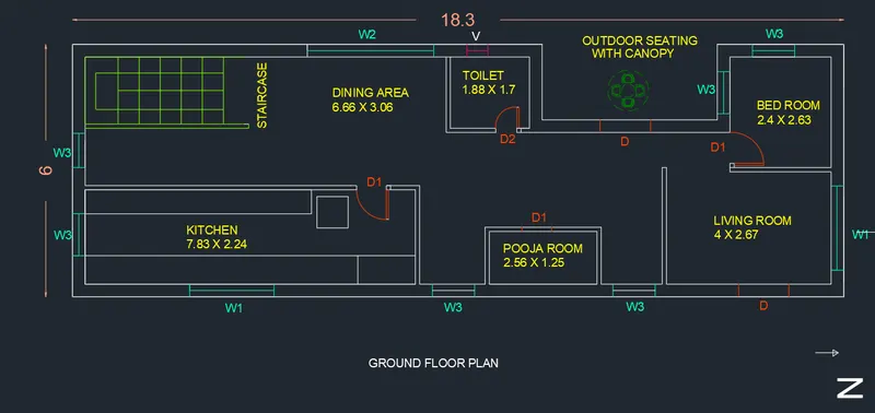
GROUNDFLOOR
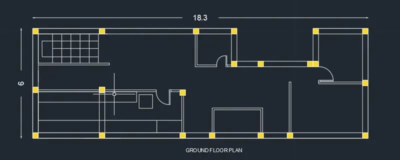
- Draw a rectangle of size 18.3 X 6m
- Draw another rectangle by taking offset at a distance 0.3m towards inside
- Now draw a rectangle of size 4 x 2.67m at right bottom corner - Living room
- Draw a rectangle of size 2.4 x 2.63m at right top corner - bedroom
- Draw a rectangle of size 7.83 x 2.24m at left bottom corner - Kitchen
- Create a space for outdoor area as shown in the figure beside bedroom
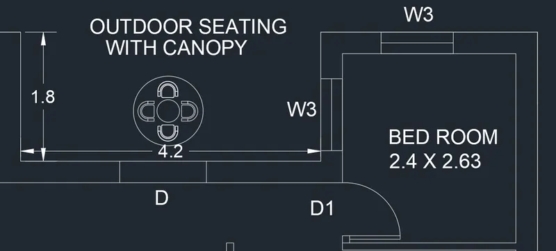
- Then create a toilet of size 1.88 x 1.7
- At top left side create a staircase as shown below
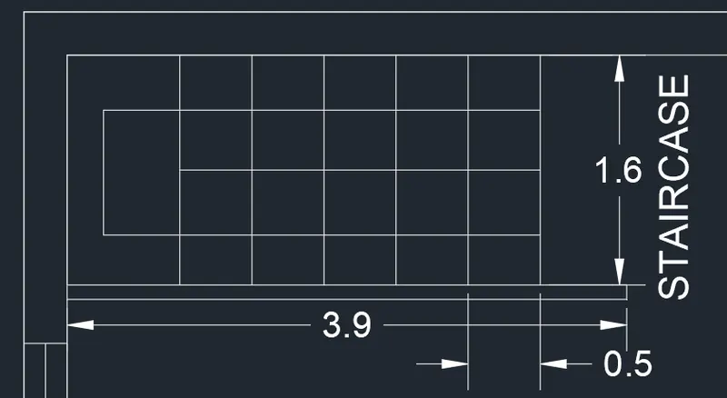
- Create pooja room of size 2.56 x 1.25 at a distance 1.4m from living room
- Door, windows, ventilator are created with width dimension given below
- Doors
D = 1.2m
D1 = 0.7m
D2 = 0.5m
D3 =
D4 = - Windows
w1 = 2
w2 = 3
w3 = 1 - Ventilator v = 0.5
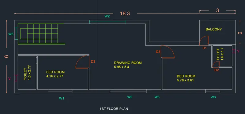
FIRST FLOOR
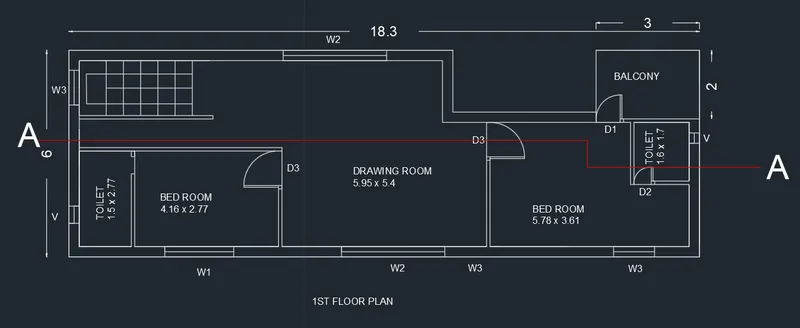
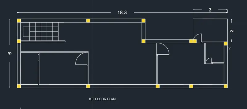
- Draw a rectangle of size 18.3 X 6m
- Draw another rectangle by taking offset at a distance 0.3m towards inside
- Create a rectangular balcony of size 3 x 2m at top right corner
- Draw a rectangle of size 5.78 x 3.61m at right bottom corner - bedroom and inside bedroom draw a toilet of size 1.6 x 1.7m
- Draw a rectangle of size 4.16 x 2.77 m at left bottom corner - bedroom and inside bedroom draw a toilet of size 1.5 x 2.7m
- Draw staircase as per dimensions given before
- Door, windows, ventilator are created with width dimension given below
- Doors
D1 = 0.7m
D2 = 0.5m
D3 = 1m - Windows
w1 = 2
w2 = 3
w3 = 1 - Ventilator v = 0.5
Elevation
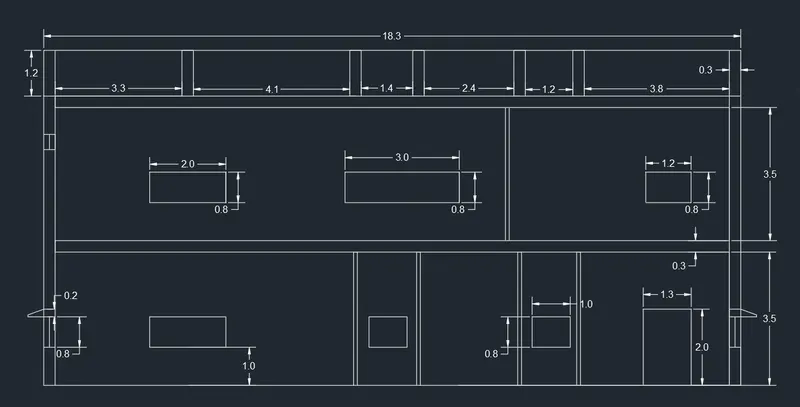
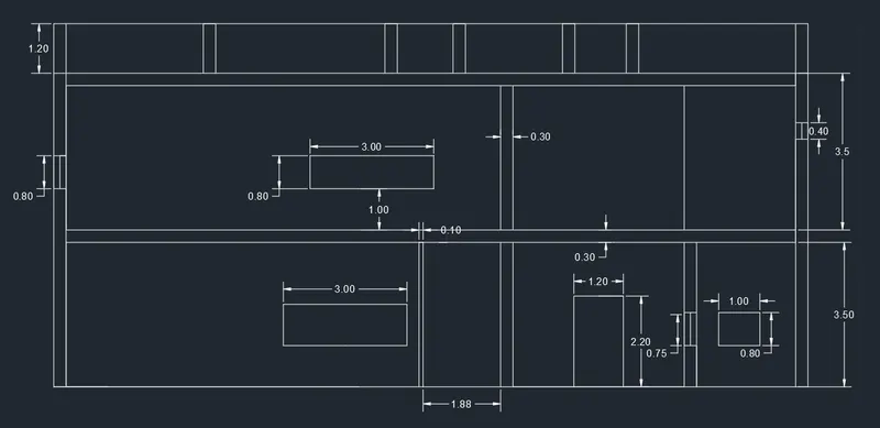
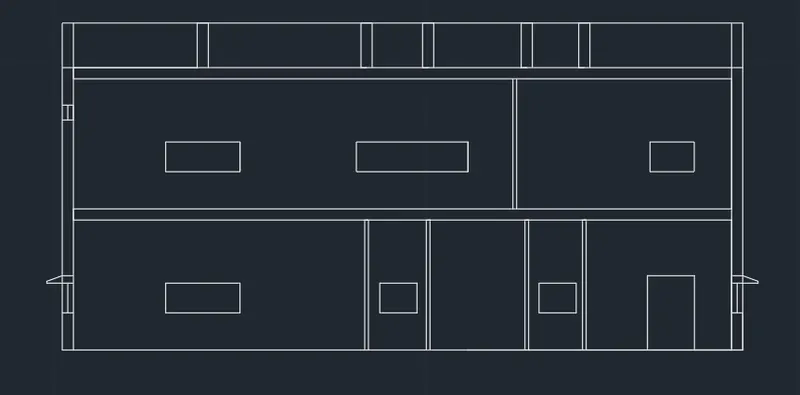
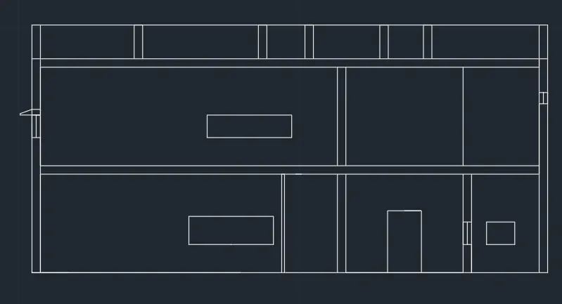
Front elevation and back elevation
- Draw a rectangle of size and draw external walls using offset
- Draw windows, doors, external walls and internal walls as per dimensions shown below
- Draw sunshades above the windows
Front elevation
Back elevation
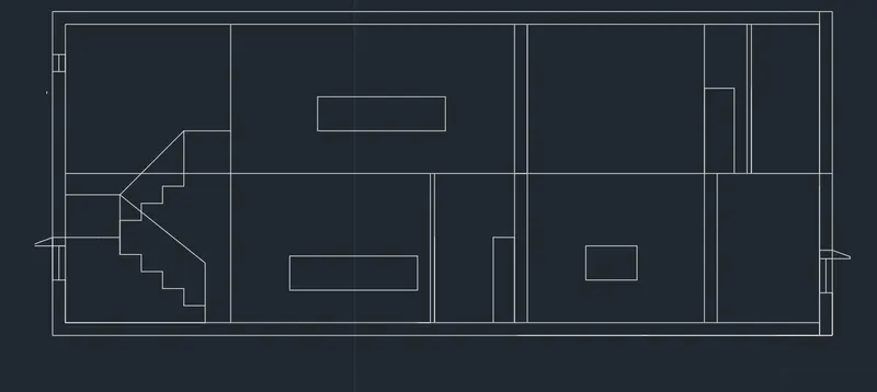
Section
- Section AA is taken as shown below
- Draw section plan consisting windows, doors, staircase, external walls and internal walls as per dimensions shown below
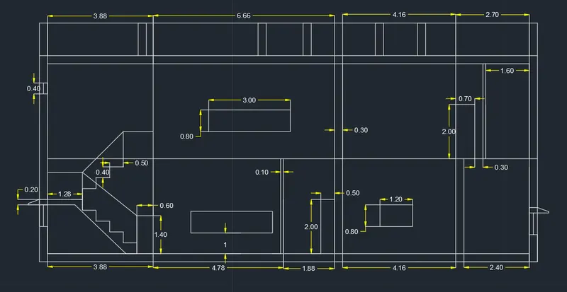
- Draw sunshades above the windows
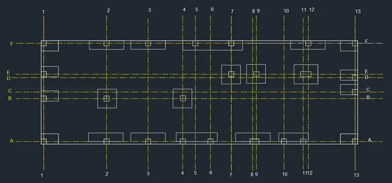
Column plan
- Column size is taken as C1= 0.3 x 0.3 , C2= 0.6 x 0.3
- Placed at different areas as shown below and hatched using hatch pattern (SOLID) and hatch scale 1
- Central lines are drawn using centerline tool
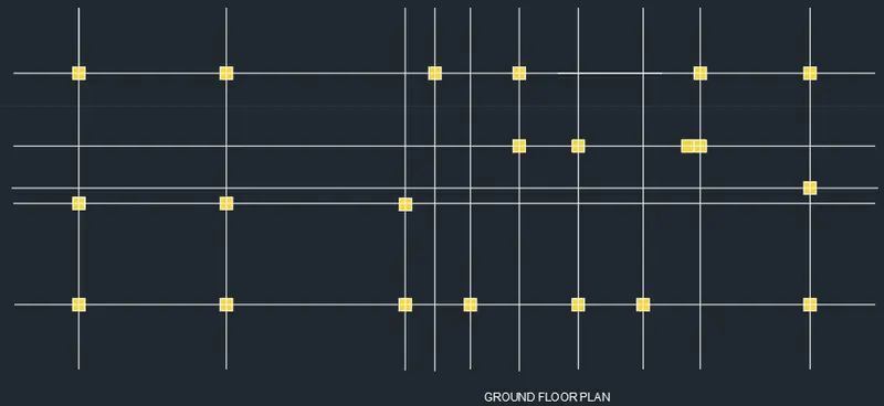
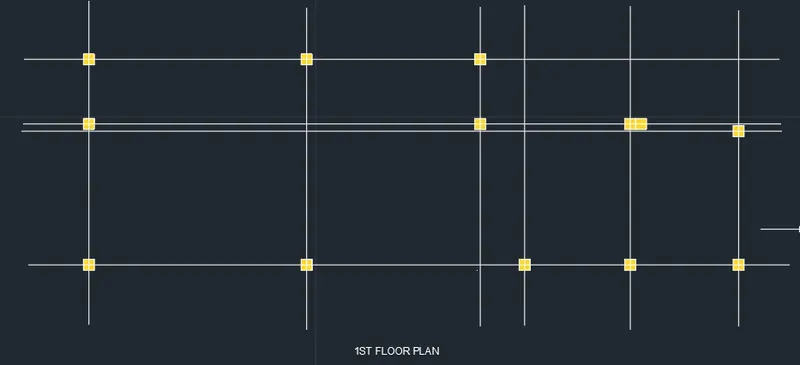
- Linetype of centerline given as DASHED
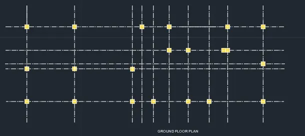
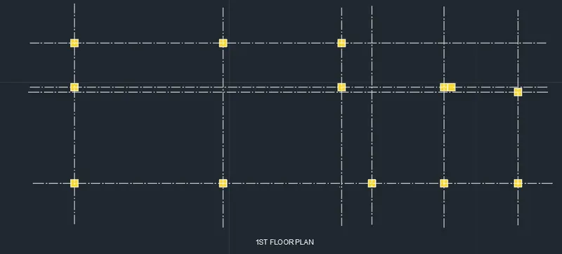
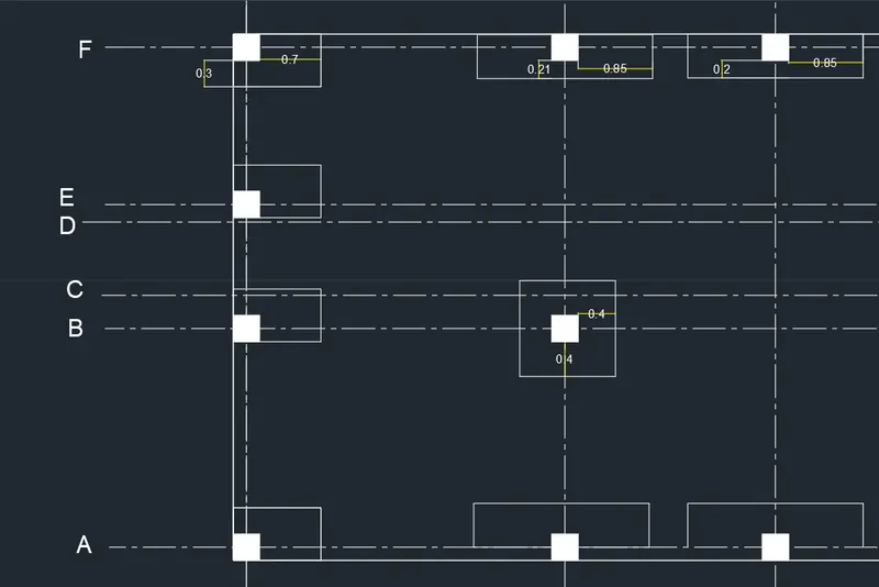
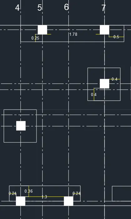
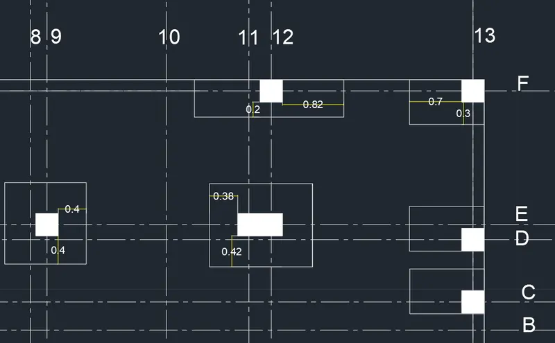
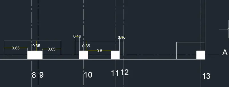
Footing plan
These are drawn by projecting column plan
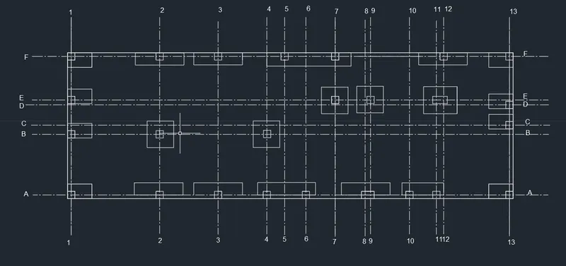
Dimesions taken for the excation of footing is given below
Beam sections
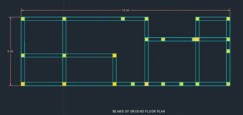
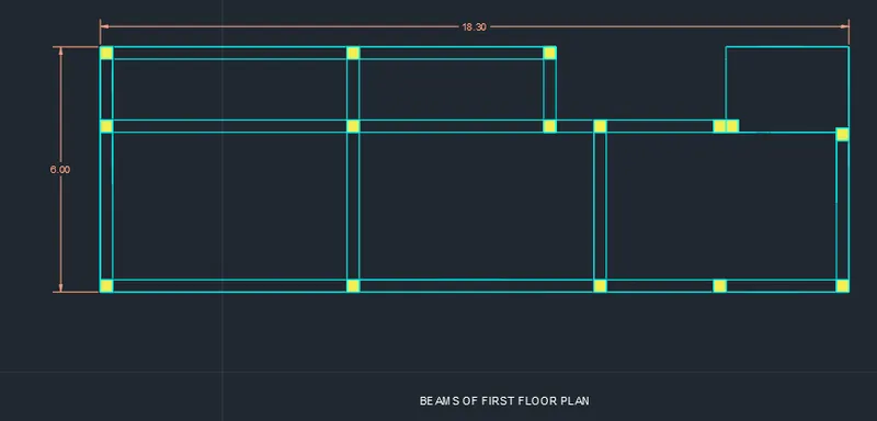
These plans are drawn by projecting floor plans and columns plans and beam dimensions taken are given below :
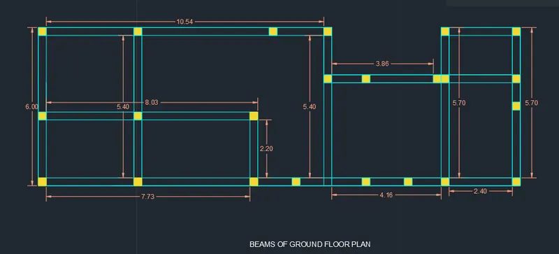
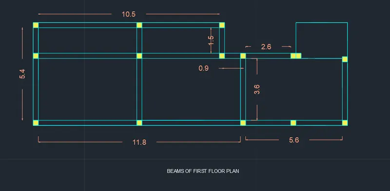
- Different layers are created such as windows, doors, ventilators, staircase, dimensions, text, centerline, outdoor and assigned accordingly
RESULTS:
GROUND FLOOR PLAN
FIRST FLOOR PLAN
FRONT ELEVATION
BACK ELEVATION
SECTION
COLUMN PLAN
FOOTING PLAN
BEAM PLAN