Project 1 _Creating an Architectural plan for the provided plot size and develop relevant basic structural drawings
Aim: To Design and Draft a layout of a residential building with the details such as:
a. Plot Size: 60’x20’(18.3m x6m)
b. Orientation- Facing East
c. Develop the following: 1. Architectural Drawing (Floor Plan, Elevations, and Sections) 2. Structural Drawing (Column, Bean, Footing Plan)
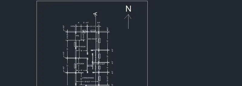
Introduction: The given project consists of a plan based on the given dimensions 60’x20’(18.3m x6m) which includes drwings such as floor plan, elevation of the structure, section of the plan, Column,beam, and footing plan. The sizes of the room of the plan are assumed as per the requirements and sizes of the structures such as column, beam and footing are assumed as per the plan and can be subjected to change as per the calculations. The proposed plan in this project consists of two floors and a balcony at the top with head room. 1st and 2nd floor consists of a living/dining room of 10'/24'x18.5' and two bedrooms of size 9'x15' respectively,kitchen of 9'x12' size, pooja room of 10'x4.5' , and two toilets of size 8'x4.5' and 6.5'x5' respectively. A balcony of size 4'x6.5' is also provided on the left side room of the plan. The wall sizes provided are 9" and 4.5" sizes wherever needed. The main door is provided as per the required facing towards East.
Steps:
a.) plan
1.
2.
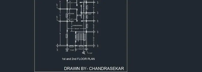
- Initially a rectangle of the plot size 60'x20' was drawn and a offset of 9" was done to set the boundary of the plot.
- Then using the offset and trim option the rooms are designed as per the fixed sizes
- The external and internal walls of sizes 9" and 4.5" are provided in the plan wherever required.
- The staires are provided at the right side bottom of the plan.
- The openings for doors are provided with width of 36" and 30" as per the room sizes.
- The midway between rooms are given with width of 4.5'
- Windows of sizes 3'x4' and 2'x2' are given as per the room sizes.
- Columns of sizes 9"x24" and 9"x30" are provided at the ends of the plan and in intenal places of the plan wherever required.
- For Colums and Windows using rectangle command the fixed sizes are drawn and all are converted into blocks and inserted in the plan using the insert command.
- Then a dimension style is fixed using the dimstyle command the plan is marked of its dimensions using the dimlinear and dimcontinue command. Dimbreak command is used to avoid the intersection between the dimension lines wherever required.
- The columns are hatched using the hatch command.
- Then using the mtext command after setting the text style texts are inserted in the plan to mark the rooms.
b.) Section AA
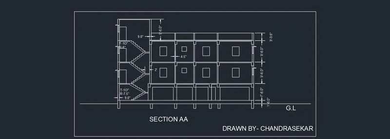
- The side section AA of the plot is considered and drawn with floor to floor height of 9.5'.
- The ground floor level height is 7.5' and a parapet wall of 3.5' is provided.
- The stairs are provided with Tread-10' and Rise 1-7.5" , Rise 2-8" respectively.
- The Cover provided at the top of the slab in paraper level is 3"
- The height from ground level is fixed at 1.5'
- For the proposed section drawing the using xline command projection lines are drawn from the plan
- A horizontal line of tentaive size is drawn.
- Then as per the floor to floor heights adopted are drawn using the offset option and the unwanted lines are trimmed.
- The doors and stairs are drawn at the left corner of the section
- For doors a rectangle of 3'x6.5' is drawn and converted into block and are inserted using the insert command.
- The Stairs are drawn using the line command as per the adopted size.
- A slab of depth 5" is assumed and provided in the section drawing of the proposed plan.
- Then using the dimlinear command dimensions are marked. The dimcontinue command is used for continous dimensioning towards the vertical direction of the diagram
- Using Text command texts are inserted wherever required
c.) Front Elevation

- The front elevation of the proposed plan is drawn as per the fixed floor heights.
- For the elevation diagram using xline command lines are projected from the plan drawing
- A horizontal line of tentaive size is drawn.
- Then the line is offseted in +y direction as per the plan height and windows are provided as per the plan.
- For windows rectangle of 3'x4' is drawn and are coverted into blocks and are inserted in the elevation using the insert command.
- The height from GL is considered as 1.5'
- Then using the dimlinear command dimensions are marked. The dimcontinue command is used for continous dimensioning towards the vertical direction of the diagram.
- Using Text command texts are inserted wherever required.
d.)

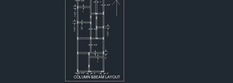
- For the Column&Beam layout the drawn plan diagram is copied and the objects such as windows are deleted from the plan
- Then the beams of sizes 9"x12" and 12"x12" are assumed and provided using the line and offset command
- Beams are connected between the columns and act as a support for slab.
- The columns are already inserted in the plan as they are converted into blocks and hatched using the hatch command.
- Then using the dimlinear command dimensions are marked.
- Using Text command texts are inserted wherever required.
e.)
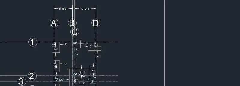
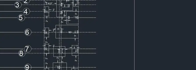
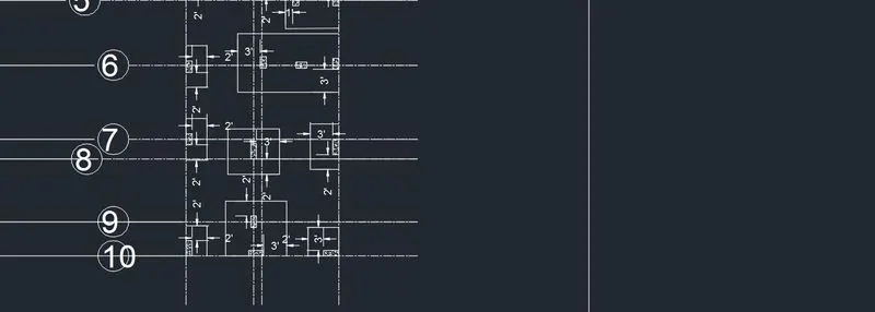
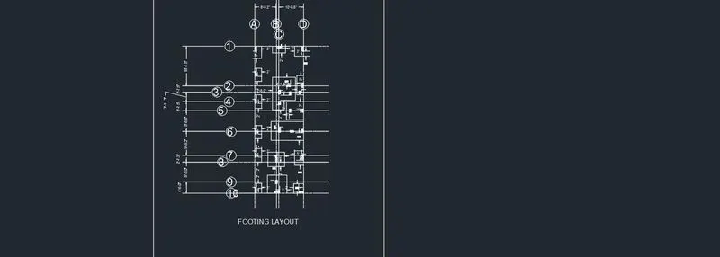
- For the footing layout the drawn plan is copied and the walls,doors,windows,stairs are trimmed off the plan.
- Then centrelines are drawn passing throught each column.
- Then the linetype of the lines are changed to Centrline from the linetype table option from the ribbon and the scale is set as per the requirement
- Then the markings are given to each centreline with numbers in the vertical direction and alphabets in the horizontal direction
- For providing markings a circle of 2' radius is drawn. Then Attributes ar defined using the Attdef command with the tag markings and are placed inside the circles and both are converted into blocks
- Then the markings are inserted and placed using the insert command
- Then Foundation of sizes 2'x3' ,2'x2',2'x1',2.5'x3' are assumed , adopted , drawn using the line command
- Combined footing is also assumed and adopted as per the requirement of the plan.
- Then using the dimlinear command dimensions are marked. The dimcontinue command is used for continous dimensioning towards the vertical and horizontal direction of the diagram.
- Using Text command texts are inserted wherever required.
Result: The given plan of plot size is drawn and the structural drawings such as column&beam layout, footing layout and architectural drawings such as Plan,Section,elevation are drawn and better insight of sectional and elevational view of the plan diagrams are learnt and provided. Usage of blocks and attributes, leader are defined and used to give better detailing in a faster way.