Project 1 _Creating an Architectural plan for the provided plot size and develop relevant basic structural drawings
AIM:
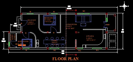
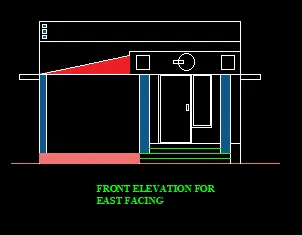
- To determine design and draft the residential layout, section and elevation with dimensions using AutoCAD.
INTRODUCTION:
- LINE: Draw lines in AUTO CAD
- POLYCON: Draw polycons with three or more sides
- RECTANGLE: Used to draw rectangles.
- CIRCLE: Command used to draw circles
- ELLIPSE: Used to draw ellipse
- ERASE: Erase object in the drawing area.
- COPY: Used to copy one or more objects
- MIRROR: Command used to mirror an exact duplicate of an object.
- OFFSET: Used to offset one object from another a distance you specify
- EXTEND – Used to extend one line to another.
- ARRAY – Use to make a rectangular or polar array of an object.
- MOVE - Used to move objects around in the drawing area
- Rotate- Used to rotate an object around a base point.
- SCALE- Command used to make an object larger or smaller.
- TRIM: Command used to trim an object from another object.
- CHAMFER- Used to put a chamfer between two lines.
- FILLET – Used to put a fillet between two lines of a radius you specify.
- DIMSTYLE- Used to modify the dimensions.
- HATCH – for hatching the objects.
- STRETCH – Used to stretch the one point of object
- SCALE – Used to resize the model/drawing itself.
PROCEDURE:
STEPS FOR PLAN:
- Open auto cad and enter UN(units command) in the command box and select type as decimal and set precision of decimal as 0.
- Select X line command and draw horizontal line and vertical line.
- Trim the unwanted lines.
- Now select offset command and give an offset of 250mm to both horizontal and vertical line drawn by X line.
- Give the offsets as follows in the X direction.
- Offset 3100 for bedroom.
- Offset 115 for internal wall.
- Offset 2250 for kitchen/drawing room/ dining room.
- Offset 115 for internal wall.
- Offset 1250 for both toilet.
- Offset 230 for external wall.
- Give the offsets as follows in the X direction.
- Offset 3100 for bedroom.
- Offset 115 for internal wall.
- Offset 3225 for bedroom.
- Offset 230 for wall on both sides of stars.
- Offset 230 for treads.
- Offset 1200 for landing of staircase.
- Offset 2400 for width of staircase.
- Offset 2250 for kitchen dining bedroom.
- Offset 1000 for veranda.
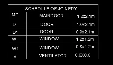
LEGENDS OF WINDOW:
SIZE OF WINDOWS ASSUMED:
- W1= 1000 X 1200
- W2=900X1200
- W=1200X1200
LEGENDS OF DOOR:
SIZE OF DOORS ASSUMED:
- D=1200 X 2100
- D1=1000 X 2100
- D2= 900 X 2100
- Windows and doors are drawn by using line command.
- Section lines are drawing by using layer and changing the layer type.
- Hatch- For hatching the columns type hatch in command box – open settings- select pattern – select pattern as AIR-CONC – select global scale factor as 0.7
- Dimension – For drawing dimension using dimension tool in the ribbon.
- Text – for naming of plan use text in ribbon in that use multiline text and keep the height of text as 200.
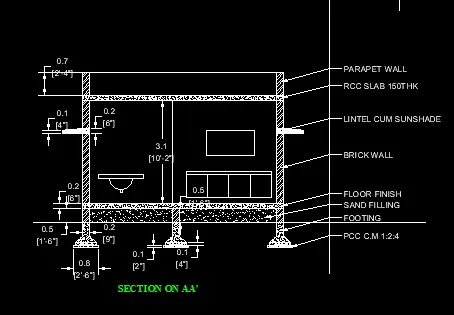
STEPS FOR DRAWING SECTION AA-
- Select x line command and external the lines from the plan in the downward manner to create projections.
- Offset 150mm from the ground level.
- Offset 3100 for ground floor.
- Offset 3100 for second floor.
- Offset 3100 for third floor.
- Offset 1000 for parapet wall.
- Offset 2500 from terrace level.
- Offset 450 from mumty for parapet wall of mumty.
- Offset 600 and offset 1200 for O.T.H
- For drawing of staircase offset 1250 for tread and offset 150 for rise of staircase.
- Offset 115 below floor level for slab.
- Draw the chajjas and windows as per the sizes considered and standards.
- Draw the railing of staircase in dash manner from the layers and change the layer to ACADISO03W100.
- Dimensions by dim linear or dim continue command.
- Select the multiline text for naming of the section.
STEPS FOR DRAWING SECTION BB-
- Rotate the entre plan drawn earlier in the 90 degrees direction o draw the section BB.
- Select x line command and take the projectors of the rotated plan in the downward manner.
- Take the projections of all internal walls of 115 mm and external walls of 230 mm.
- Draw a base line to draw the section BB.
- Offset 150 from base line.
- Offset 2450 for ground floor.
- Offset 2850 for first floor.
- Offset 2850 for second floor.
- Offset 2850 for third floor.
- Offset 1000 for parapet wall.
- Thickness of slab is assumed to be 125mm.
- Offset 125 room each floor in downward manner.
- Dimensions – Use dim linear or dim continuous for giving the dimensions.
- Draw the windows as desired by using the line command.
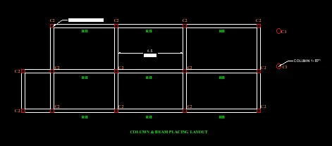
- Calculate the self- weight of these Columns and Beams:
C1 (230 x 230) :
Let’s take a column of size C1 (230x230)
Assume height =1m
Self weight of column C1 is,
Total volume of concrete = 0.23x0.23x1
=0.053KN/m3
Unit weight of concrete = 25KN/m3
Self weight of column = 25 x 0.053
=1.33 KN
C2 (R-150MM) :
Let’s take a column of size C2 150MM
Assume height =1m
Self weight of column C2 is,
Total volume of concrete = 3.14X(0.15)2 X1
=0.07KN/m3
Unit weight of concrete = 25KN/m3
Self weight of column = 25 x 0.07
=1.77 KN
Calculate the wall load on a beam of height 3.1M?
Let’s calculate the wall load for a height 3.1 m
-Height of the wall = 3.1m
- Thk.of the wall = 230mm
- Unit.wt of brickwall = 20KN/m3
- Dead load of wall = 20 x3.1 x0.23
=14.3KN/m
TOTAL LENGTH OF WALL = 69.5m
=14.3x69.5
=991.1KN
Calculate the self-weight of a slab of 150mm thickness and span 18.3m x 6.1m?
Self – weight of column is,
Total volume of concrete
=18.3 x6.1x0.15
=16.75KN/m3
Unit weight of concrete= 25KN/m3
Self weight of slab = 25x 16.75
= 418.6KN
RESULT:
To determine design and draft the residential layout, section and elevation with dimensions using AutoCAD.