Project 1 _Creating an Architectural plan for the provided plot size and develop relevant basic structural drawings
AIM-: Design and drafting of the plan of a residential building of plot size 20x60'{18.3mx6.0m) plot orientation is East facing.
after drafting of plan than also creating the section and elevation and design of Beam and columns and footings as structural drawing details.
Procedure :-
Start AutoCAD 2020
- Command UN @ engineering with Precision 0.0
- Xline command and drawn lines in X&Y Directions @ offset outer walls 9" and inner walls 4.5" by taking outer plot dimensions 20',60'.
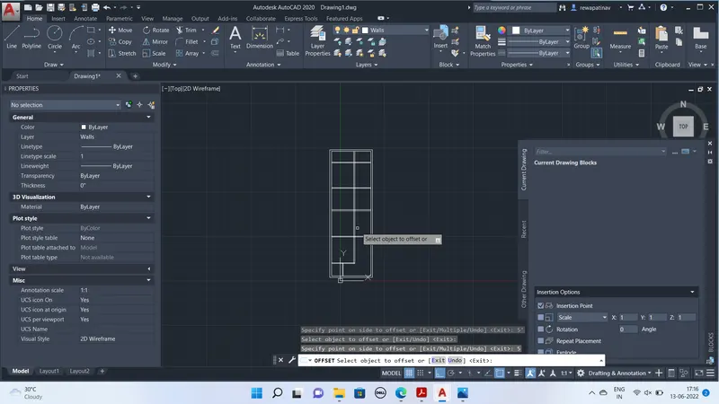
by makig offset and Trim plan is drawn WIth Following spaces
Bedroom 2 nos
Kitchen 1 nos
Hall/
Dining Hall
Porch for parking
OLT Duct
Layers Created
Walls
Columns,text, Dimensions,Floor HActing, walls hatching and
For floor hatching transperenacy setup done at 70%
Blocks Created for
Window Door and Columns of Size 9x12"
Doors size taken as 3' ,2'6" As per the required for the specific perticulars
In main date of 7' approx is ddrawn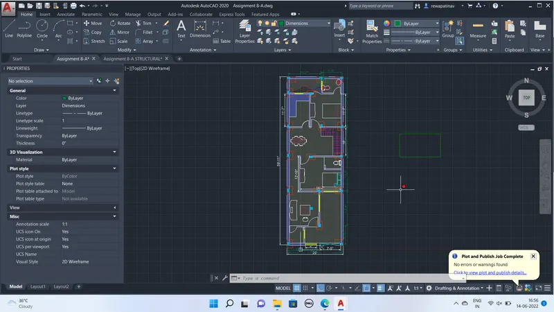
Facing is setup by rotate the plan with 90 anticlockwise
ADC Command :=Autodesk design center used to insert sofa, dining table sink WC and all the blokcs shown oin the figure above and scaled accoding to the fit apperance.
Preparation oc coliumn Layout
Columns are placed at the specific distance and intersection of wall avoiding the columns= nit obstruct the spacing of the rooms
Than Footin plan layer created with red color and drawn the rectangle of 2'x3'
and footing layout palced at the columns matching geometric centers except coluimns at corners.
DiMLIN Used to dimensons.
Creation of Columns Layout
Disabled all layers excepting tge column and footin layer than Copy the Column and foorting component at a place
Than Create a layer of dashed Line with scaled suitablly and than join all the collumn Lines . See the figure Below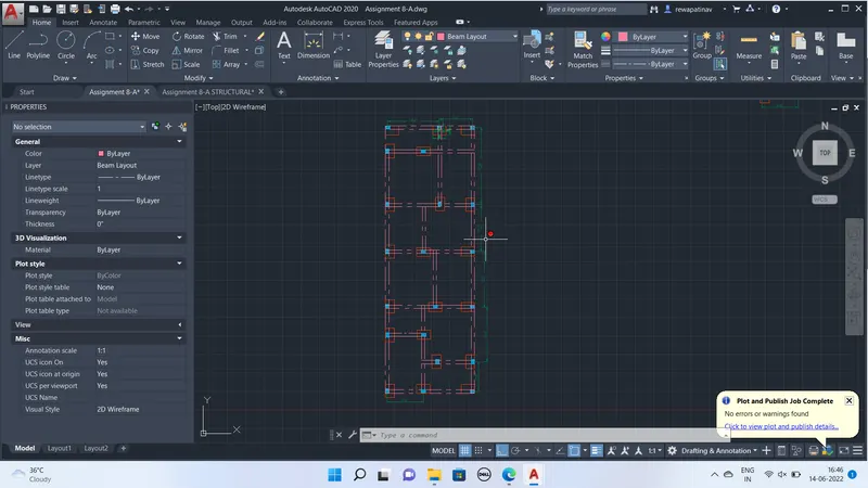
Creating of Structural drawings of Footing design Columns And Beam i am sharing my snaps below
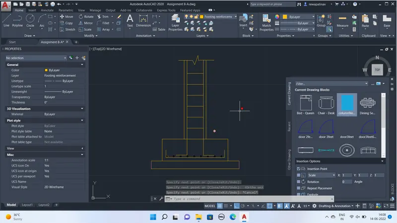
By assuming the footing thickness 8" M20 and for PCC 4" M10
Reinforcement details are drawn woth the spacing of the main and distribution reinforcement of 6"and size of footin is taken as 3'x2'
and for PCC offset of 4"
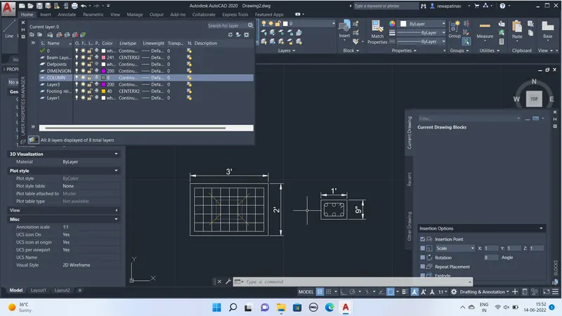
Hatching is provided for the concrtete and PCC work As shown
Also Columns and beams reinforcement details are provided in the drawing layout below
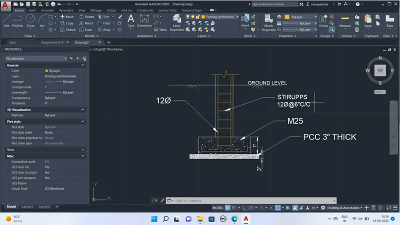
Command used Mleader ,Text ,dimensions and to fit in the layout double viewport is used and than Modelspace command used to fit in the viewports
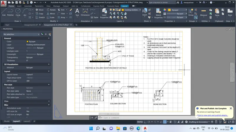
Beams layout with the dimension of 9"x12" are drawn with dashed lines see the snap below
Creating of elevation-:
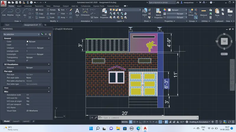
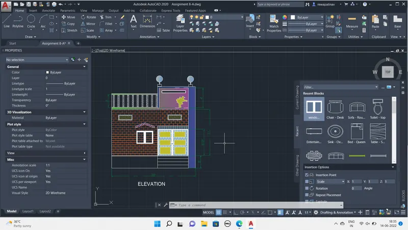
For creation of elevation of the plan Projection :Lines are drawn and than Floor Height of 11' is taken by Offset and plinth level at 3 Feets
Also satirs before the Main gate is drawn with riser of 6" and treads with 9"
I created the Main door as the block by using using various opions of hathcing and providng the paterna and color that i am sharing the some snaps of main gate creation below of size 7'6" and height of 8'
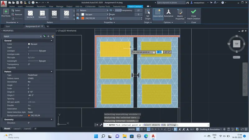
Also created the Block for window elevation with panels Tranceparancy 80% and Choosen color as to the glass and than Parapat walls and design is provided above the slab
Result :-Finally all the drawing are ploted on the A3 pages with suitable orientations and Collected all the drawings as PDF for whole Project