Project 1 _Creating an Architectural plan for the provided plot size and develop relevant basic structural drawings
AIM:
*To create an architectural drawing (Floor plan, Elevation and Sections ) for the given plot size with relevant structure Drawings.
INTRODUCTION:
*The Architectural drawing is done by using Autocad software and its various tools.
*The instructions and details provided are :
*Plot size :60' x 20'
*Facing east
*PROCEDURE:
1.ARCHITECTURTAL DRAWINGS:
STEP1:
*New drawings is opened in autocad with imperical setting , engineering usit of measurement and 0'-0'0" is set as per precision.
*Limits are set by using Limits command.
*Drawing uniktys are sert to engineering and 0-0'.0".and inches in the drawing style dialouge box.
*STEP2:
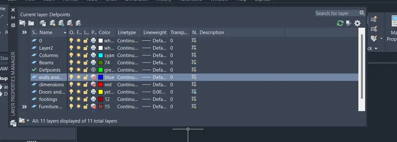
*Useing layer properties manager by giving layer command the required layers are created and given nunique colours.
STEP 3:
*Doors and Windows is set as current layer from from layers panel in ribbon.
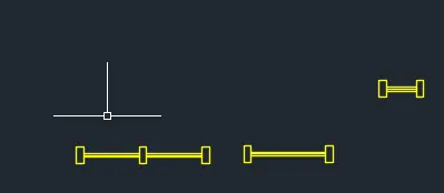
*Window frames are created using RECTANGLE command.
*Then the line and offset command is used to create the windows.
*Two windows and one ventilater W1,W2 and W3 of lengths 6',4' and 2' respectively are created.
*Block command is given and the windows are converted into blocks with their respective names.
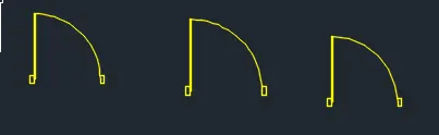
*The door hinges are created using rectangular command .
*The door frame is created by using LINE and OFFSET command.
*The swing is then created using circle command and the rest is trimmed off using TRIM command.
*Three doores arre craeted D1,D2, and D3 with the sizes 3'3",3' and 2'6" respectively.
*BLOCK command is given and the doors are converted into blocks with their respective names.
*BEDIT command is used to convert them into Dynamic blocks in block editor mode.
STEP4:
The north direction is depicted using Qleader and Dtext commands.
*The Walls layer Slab layer is set as current layer from layers panel in Ribbon.
*Xline command is given and vertical and horizontal construction lines are created.
*Using Offset command the outer walls of the building is created and the rest of the lines are trimmed off using trim.
*The inner walls,rooms, are then created using Offset and Trim commands.
*The current layer is changed to stairs from layers pnel in Ribbon.
*The stairs are creted using line tool and the tread distance is taken as 10".
*The treads are offseted using OFFSET to create stairs.
*The current layer is changed to doors and windows from layers panel in ribbon.
*The doors and windows are inserted in the required areas using INSERT command.
*The sunshade is given loading ISO dash line from LINETYPE MANEGER.
*The current layer is changed to columns from layers panel in Ribbon.
*One column of size 1"x9" is created .
*It is then copied and placed wherever necessary using the COPY, MOVE , ROTATE commands.
*This Layout is copied and pasted in another location.
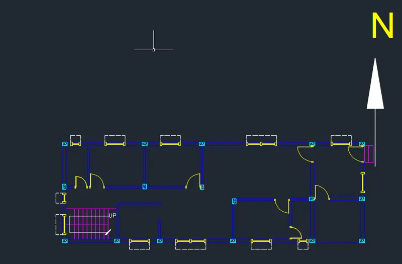
STEP5:
*ADC command is given to open the Design Centre.
*The required drawings are imported to the drawing which are saved are blocks.
*They are selected and placed in the furniture and fittings layer from layers panel in Ribbon.
*They are then inserted in the plan using INSERT command.
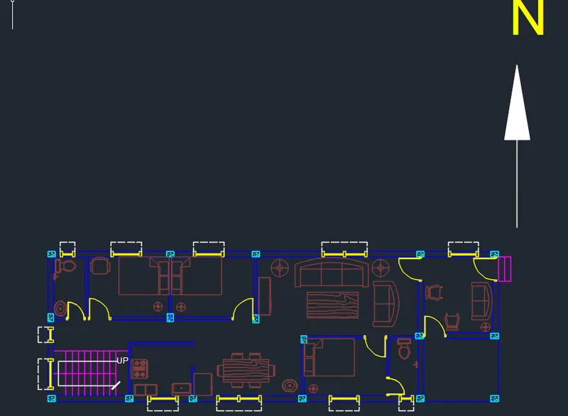
STEP6:
*Dimensions and Text is set as current layer from layers panel in ribbon.
*DIMSTYLE command is used to specify the dimension style , font and size.
*Dimlinear command is used to create overall dimensions.
*Dimcontinue command is used to create a rest of the dimensions.
*MTEXT command is used to create the TEXT.
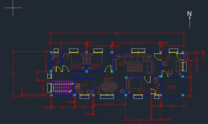
THE GROUND FLOOR PLAN IS CREATED.
STEP7:
FIRST FLOOR PLAN:
*The layout copied from thr ground floor plan is edited as required using erase,trim commands.
*The Walls and Slab layers is set as current layer from layers panel in Ribbon.
*The required walls are created using LINE and OFFSET commands.
*The current layer is changed to Doors and Windows from layers panel in ribbon.
*The doors and windows are inserted in the required areas by using INSERT command.
*The sunshade is given loading ISO dash line from LINETYPE manager.
*Furnitures and fittings is set as current layer panel in ribbon.
*Thet are then inserted in the plan by using INSERT command.
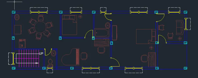
*STEP8:
*Dimensions and Text is set as current layer from layers panel in ribbon.
*DIMSTYLE command is used to specify the dimesions style,font, and size.
*DIMLINEAR command is used to create over all dimension.
*Dimcontinue command is used to create a rest of the dimensions.
*MTEXT command is used to create the TEXT.
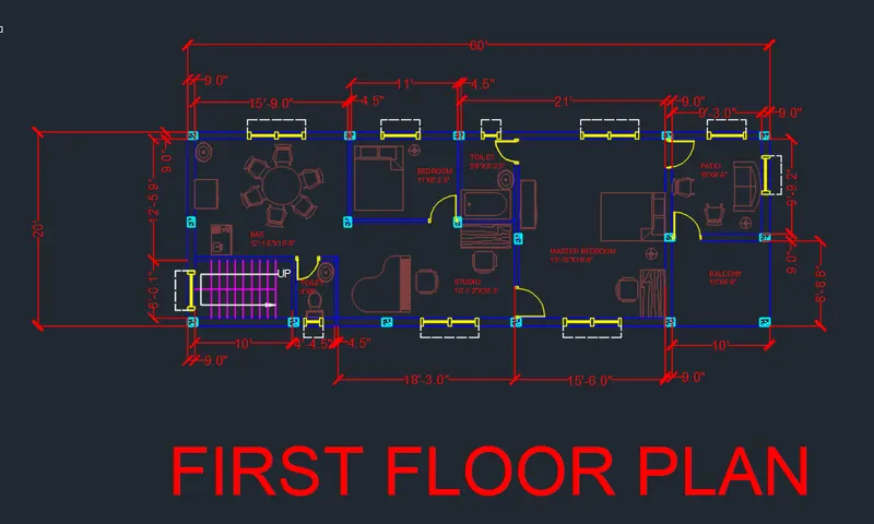
The first floor plan is created.
FRONT ELEVATION:
STEP1:
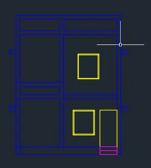
*The dimensions and text layer is froozen and the ground floor plan is copied and pasted in other location using copy.
*Then it rotated using command rotate for 90degrees.
*Using xline the projections of the sunshades,stairs, columns,doors and windows are made.
*The rest of the lines are trimmed off using trim.
*Parapet wall are craeted using LINE and OFFSET commands.
STEP2:
*Hatch command is given and brstone hatch is used for frontwall.
*DIMLINEAR command is used to create overall dimension.
*Dimcontinue command is used to create a rest of the dimensions.
*The components are then selected and then placed in their resoective layers from the layer panel in the ribbon.
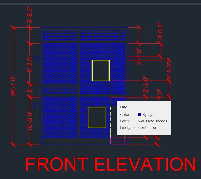
The front elevation is created.
SECTION A:
STEP1:
*The dimensions and text layer is froozen.
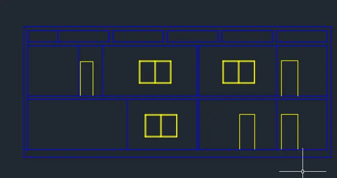
*The ground floor plan and elevation is copied and pasted in other location using copy.
*Using xline the projections are made.
*The rest of the lines are trimmed off using trim.
*The components are then placed in their respective layers from the layer panel in the ribbon.
STEP2:
*Current layer is set to Dimensions and text from the layer pnel in the ribbon.
*Dimlinear command used to create over all dimension.
*Dimcontinue command is used to create a rest of the dimensions.
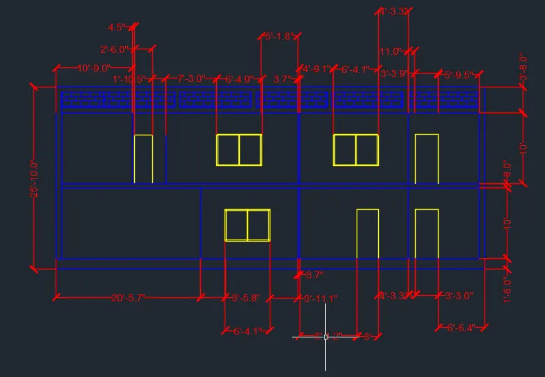
section-A drawing is created
FINAL RESULT:
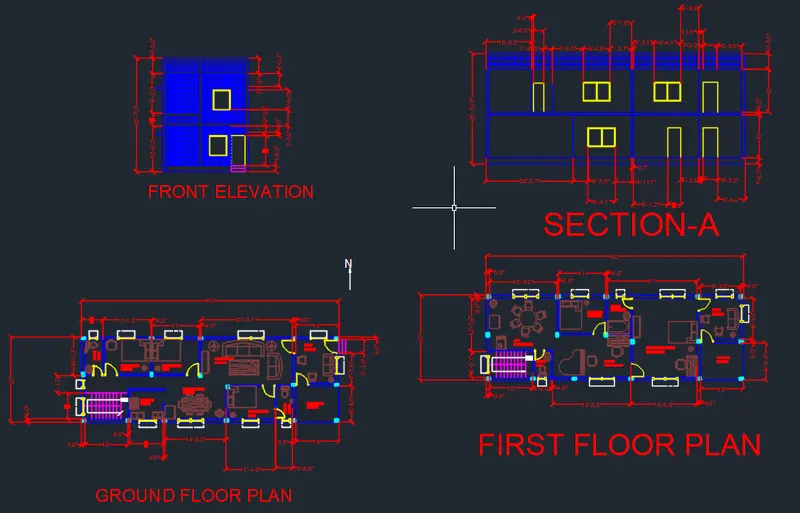
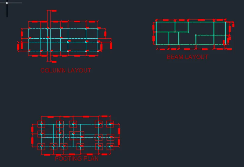
2.Structural drawings:
STEP1:
*Every layer other than collumn layer is frozen from layer panel .
*The columns are then copied and pasted in other location using COPY command.
*Grid lines are drawn using XLINE command through thr middle of each column.
*The lines are selected and in properties menu the line type is changed to ISO dash.
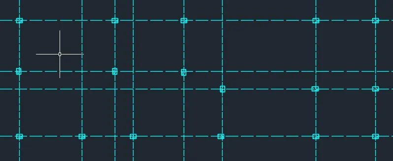
STEP2:
*Dimensions and Text is set as current layer from layers panel in ribbon.
*DIMLINEAR command is used to create over all dimension.
*Dimcontinue command is used to create a rest of the dimensions.
*DTEXT COMMAND is used to create the text.
*It is copied and pasted in every room using copy command.
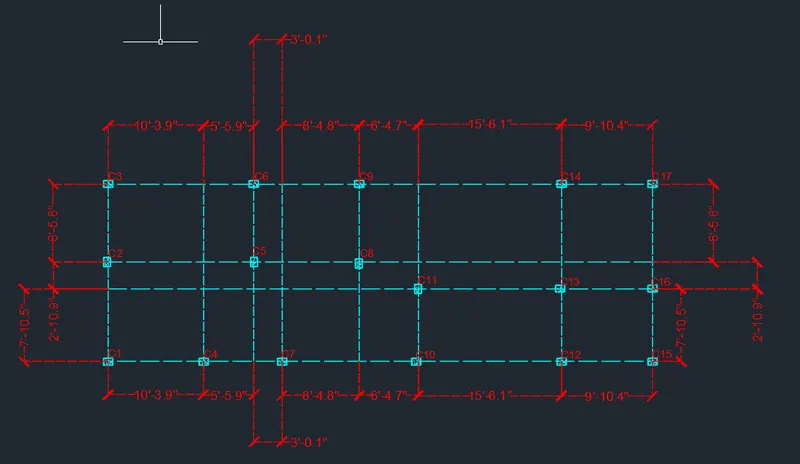
The Column Layer has been created.
STEP3:
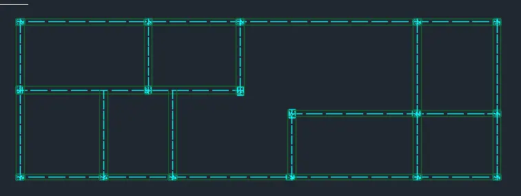
*Beams is set as current layer from layers panel in ribbon.
*The beams are drawn by using LINE and OFFSET commands.
*The rest of the lines are trimmed off using TRIM command.
STEP4:
*Dimensions and Text is set as current layer from layers panel in ribbon.
*DIMLINEAR command is used to create over all dimension.
*Dimcontinue command is used to create a rest of the dimensions.
*DTEXT COMMAND is used to create the text.
*It is copied and pasted in every room using copy command.
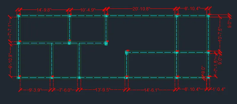
The Beam layout is created.
STEP5:
*In the column layout drawing the dimensions and text layer is frozen.
*The remaining columns and grid lines are copied and pasted to a new location using COPY.
*The footings are drawn after the layer is set to footing in the layer panel.
STEP6:
*Dimensions and Text is set as current layer from layers panel in ribbon.
*DIMLINEAR command is used to create over all dimension.
*Dimcontinue command is used to create a rest of the dimensions.
*DTEXT COMMAND is used to create the text.
*It is copied and pasted in every room using copy command.
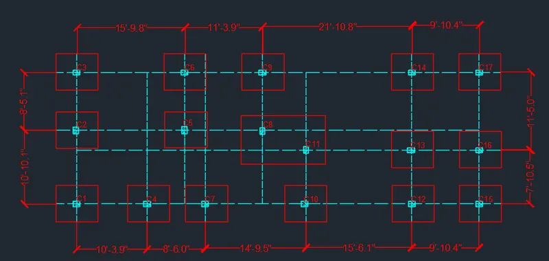
The FOOTING PLAN is created.
FINAL RESULT: