Creating a Floor plan, Footing detail and Isometric view using AutoCad
Aim : To create a details of floor plan ,footing and isometric view using autocad.
Introduction: Creating a 2-D plan by using the commands like line,PL,O,TR,etc.,by using this common commamands we can draw a number of floor plans and in the floor plan there will be a footing which shows the direction to go on the higher floor,atlast there will be explanation of isometric view using autocad.
procedure: Open a autocad software then open a new file, select default setting as imperial then select units as inches in engineering.
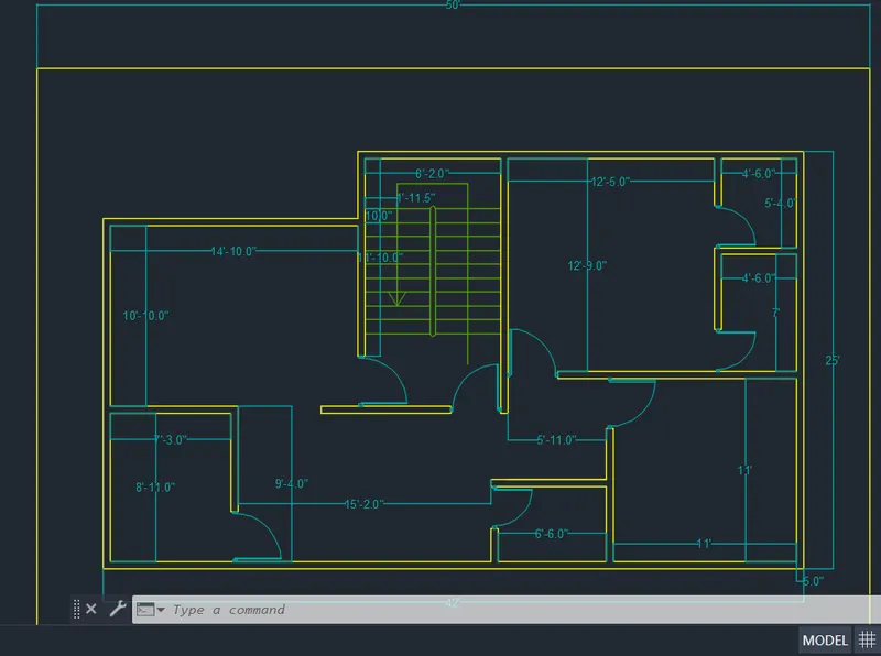
I] Draw a rectangle of size 50'x30' and assume it is a plinth area.
ii]Explode a rectangle and draw build up area of size 42'x25' by the command [O] OFFSET.
III] Then offset of 5" for all the build up area walls.
iv]Then all the rooms has been drawn according to the required sizes.all the walls has been taken the 5.0".
v]from the right side take offset of 11' then from bottom right take the offset of 11' up then remaing all lines trim it then a 11'x11' room will be drawn at bottom right of the plan.
vi]Again by doing offset the rooms size of 4'6"x7' and 4'6"x5'4" drawn for washroom and bathroom.
vii] Beside to left of this washroom and bathroom there is a bed room of size 12'5"x12'9" has been drawn with a wall thickness of 5".
viii]Left to this bedroom there is a stair cases drawn of size 8'2"x11'10" and the size of the tread is 1'11.5" and landing size of 3'.
ix]Beside to stairs there is a bedroom of size 14'10"and 10'10".
x]Below to this room there is a drawingroom
xi] Beside to this we have drawn a hall with dinning table
xii]At last there is a kitchen room and handwashing rooms.
xiii] Draw a doors by drawing a small rectangle with a line of door size
RESULT:A well designed plan has been drawn as per the required dimension area with proper waastu consideration, and staircases also drawn in the plan which is showing the direction of riser to top floor.
Isometric view using autocad: isometric is a view in which 2-d object represent 3d-object,it mean the 2-d object looks like 3-d but it is not 3-d.isometric object will be 2-d object itself, it only represent 3d.
i]UCS reprent X and Y directions, and cross hair represent 90degrees and 0 degrees,when we go on isometric view the angle gets changes.
Lets see how we can go from 2-d view to isometric view and different plane with angles.
Two methods to go for ismometric view
1]Menu bar 2]DS [Drafting setting] command.
ii]DS enter click on snap and grid ,then snaptype do it ismometric snap then ok.
iii]then crosshair angle gets changed.
iv] There are three planes in the isometric plane
1]isoplane left 2] isoplane right 3] isoplane top
*]In isometric left in top and left only the cursor moves
* In isometric right the cursor moves in top and right.
* In isometric top the cursor moves in both left and right.
* The circle drawn in isometric will be seen like ellipse.