Project 1 _Creating an Architectural plan for the provided plot size and develop relevant basic structural drawings
CHALLENGE-08
AIM: To create a plan, section, elevation, column position, beam position, and footing layout.
INTRODUCTION: In this drawing we can create a building layout and their dimension is assume and their position are also assume as per wastu the plot is east facing, in this plan I am creating plan, section, elevation, beam position, column position, and footing with their dimension.
PROCEDURE:
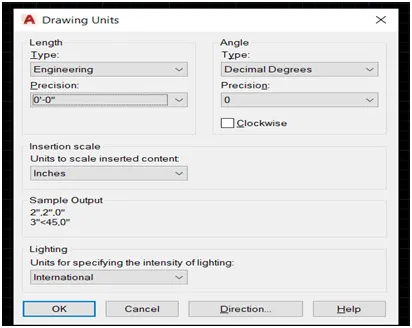
1.Open auto cad and set the drawing unit
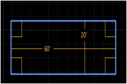
2.Create a rectangle 60’x20’
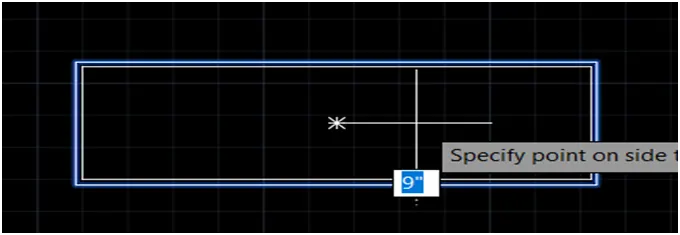
3.offset inner side 9”
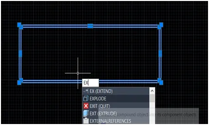
4.Explode the rectangles
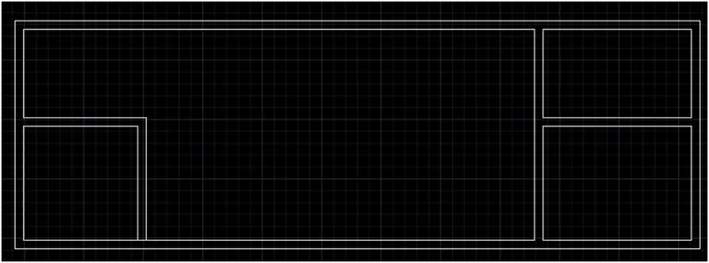
5.Offset the line 12’
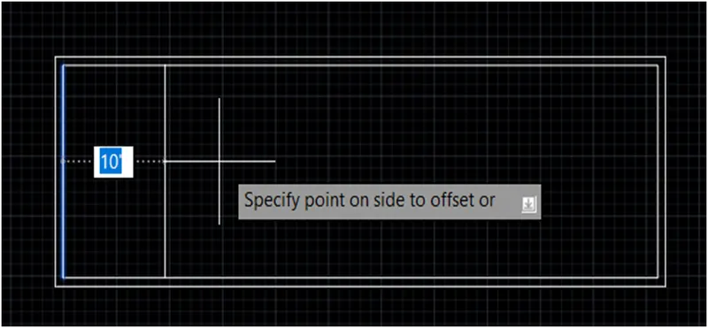
6.Again offset 9” and offset the bottom line 10’ and 9”
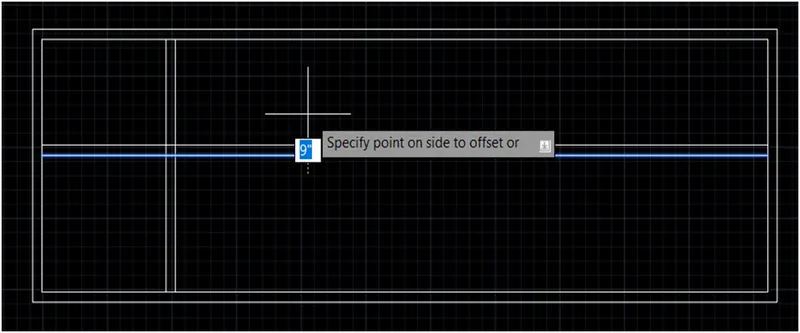
7.Offset right side13’ and 9”
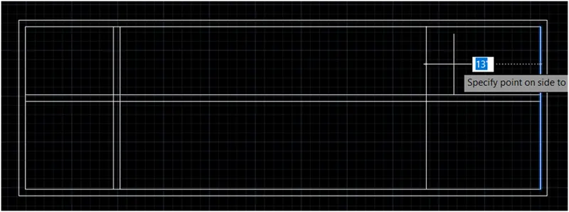
8.Trim the mid portion
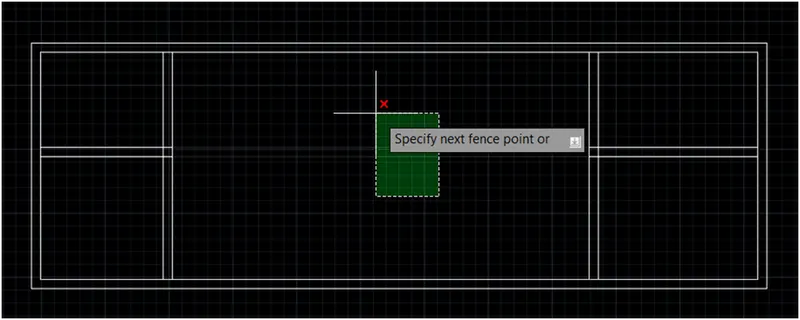
9.Then fillet the drawing as shown in figure
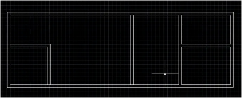
10.Again offset right to left 12’ and 9” as shown in figure
11.Then trim the top edge and offset 12’ and 9”
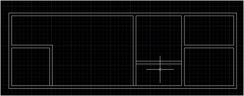
12.Then extend the line

13.Then fillet the line
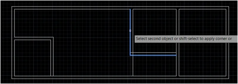
14.Then create a line at midpoint as shown in figure
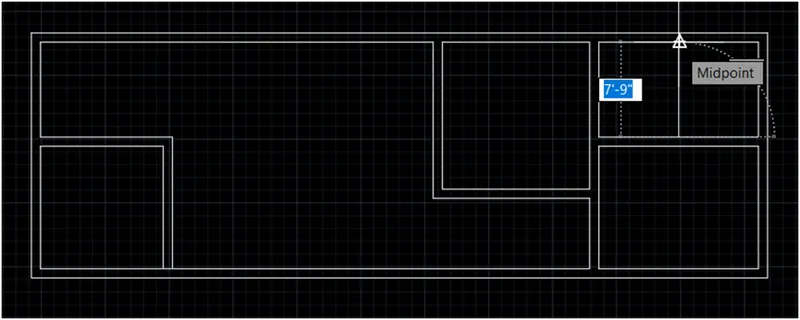
15.Go offset both side 2”
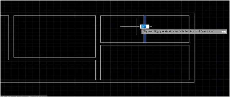
16.Delete the center line and trim the edge
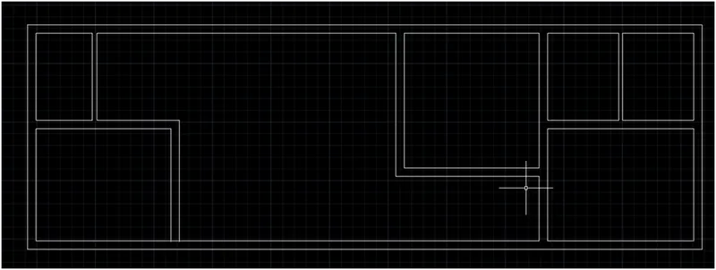
17.Then create a stair case trade 9”
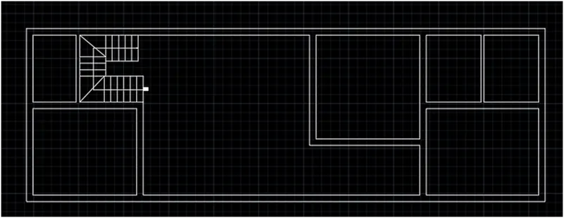
18.Then cut the door size is 3’3”
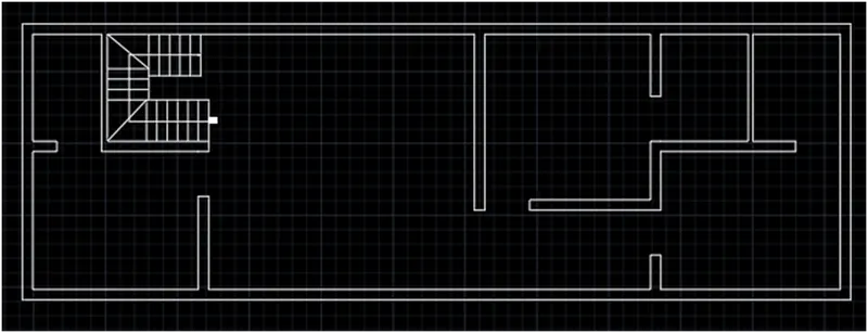
19.Then create a window and cut the main door 5’and window is also 5’
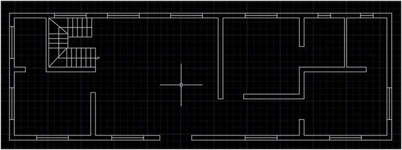
20.Then place a door symbol
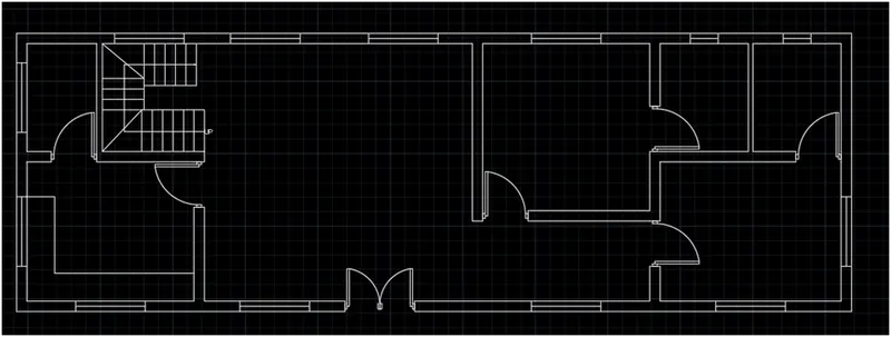
21.place the component of the drawing and give the details of the drawing through text command
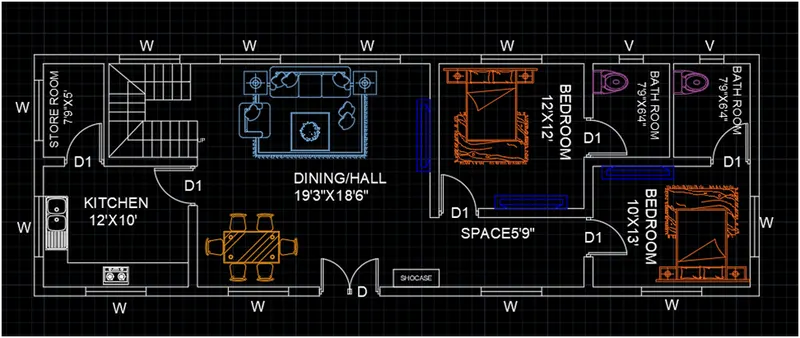
22.Then create cantilever of the window places and door also and change the line as dash line
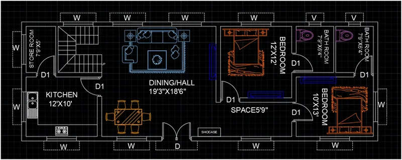
23.draw the section line and cut the section-AA of the drawing
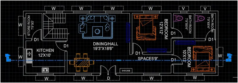
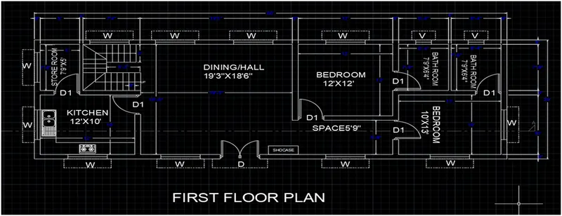
24.After creating ground floor we create a first floor as same as ground floor then give the name and dimension of the drawing before the dimension, set the dimension settings and also text settings
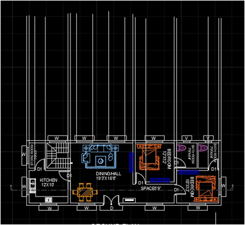
25.After creating a plan we go for section of the drawing draw the vertical line as shown in the section
26.create a horizontal line at any point and offset 6” two times
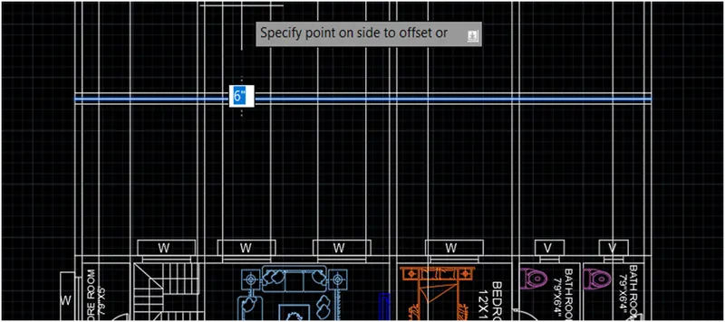
27.Then trim the bottom line
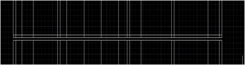
28.Then delete the all bottom line as shown in the figure
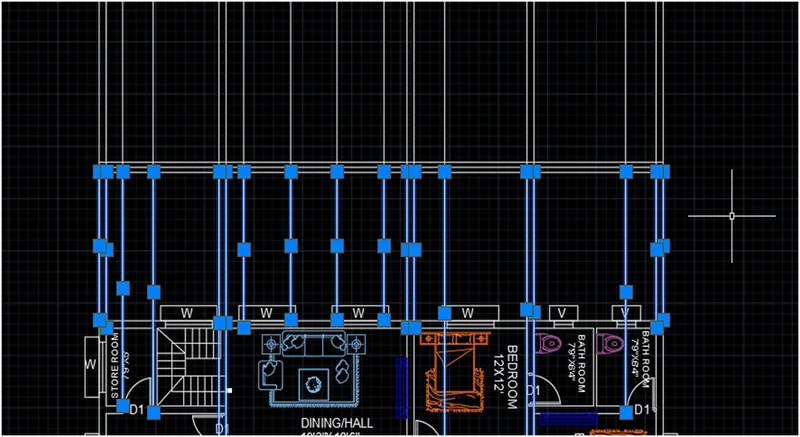
29.Then offset the floor height 10’ and 5” slab thickness again 10’ and 5”
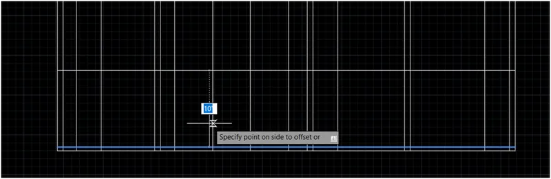
30.offset the floor line 7’ as door height and lintel level Then trim the other portion as shown in figure
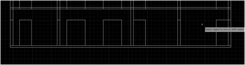
31.create a door window and cantilever as shown in figure
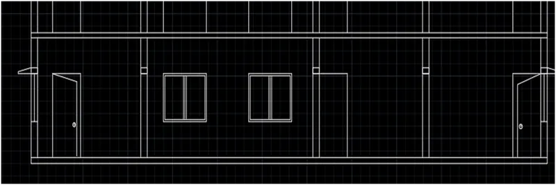
32.Hatch the wall portion and create a first floor as same as bottom process and also create a bottom portion 1”thick tiles and 6”thick H.F.s. or P.C.C. and 11” thick sand filling and bottom wall as shown as continuous line and hatch that portion
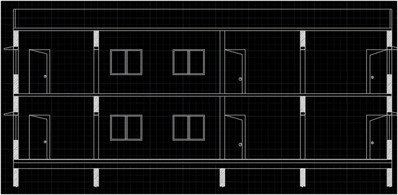
33.Hatch the window as glassed
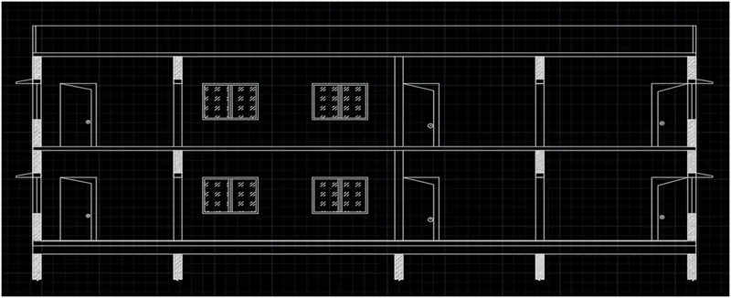
34.Then hatch the 11” sand filling
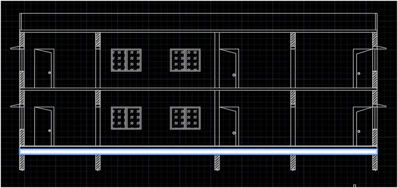
35.Also hatch P.C.C Layer and tiles layer
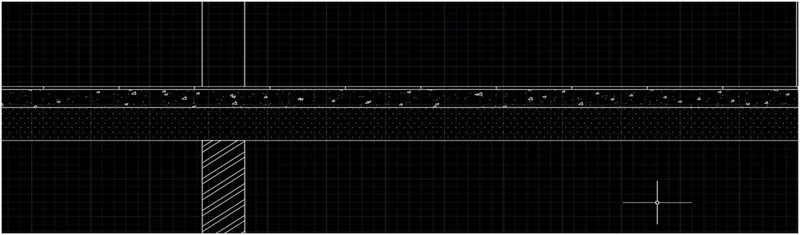
36.Then hatch the top slab as reinforced concrete
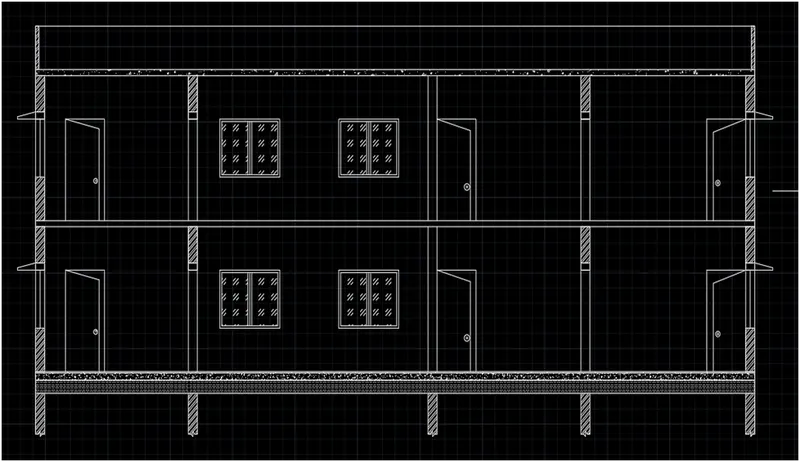
37.Then hatch the middle slab
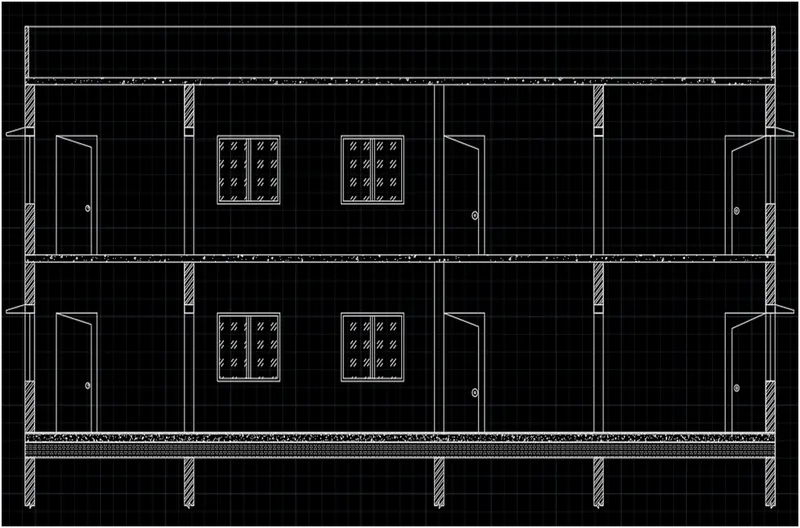
38.Then hatch the cantilever
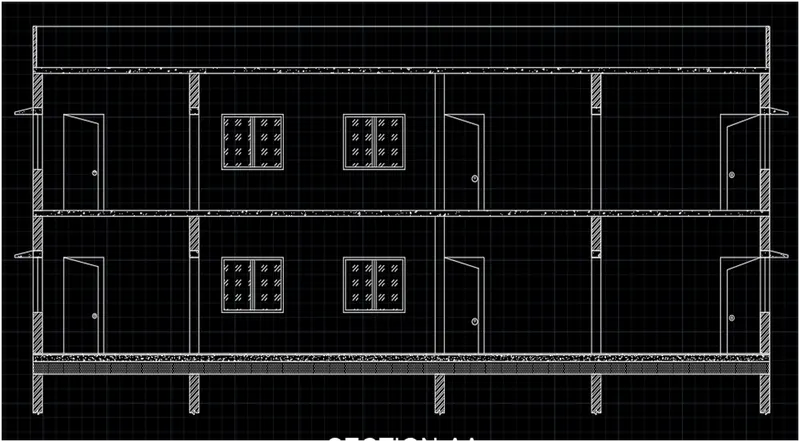
39.Then crate a tower of the stair case height is 10’ as floor height and give the dimension and the name of the drawing.
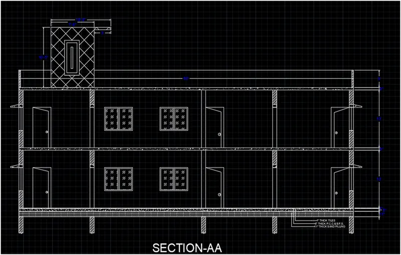
40.After completing section go for the elevation of the drawing draw the vertical line as shown in figure.
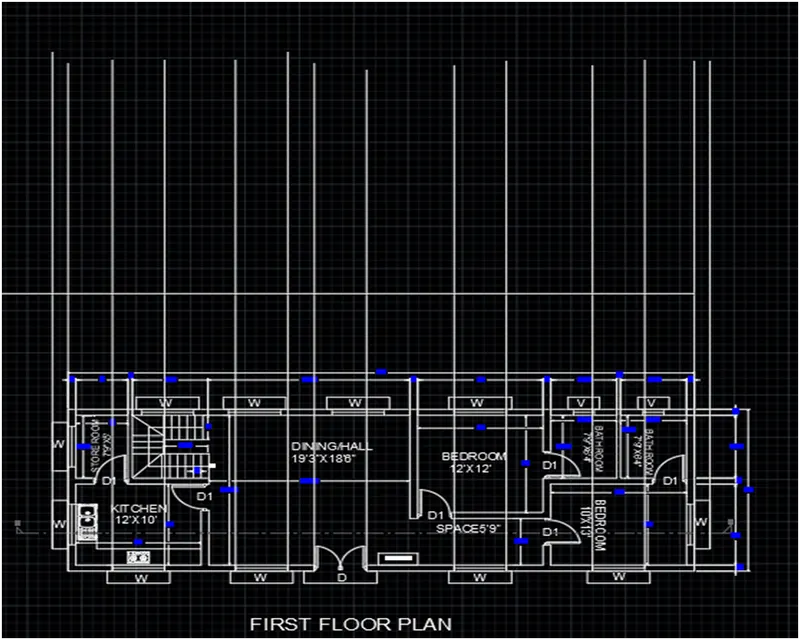
41.create horizontal line and offset the lone 9”, 9”, 10’, 5”, 10’, 5”, 3’, 7’
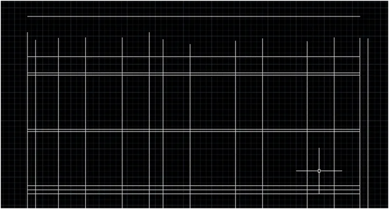
42.Trim the bottom line and delete the all bottom line as shown in figure
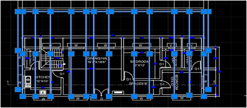
43.Go for 7’ offset and 4’ down word from 7”offset line because window height
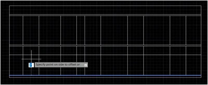
44.Then trim the mid line and unwanted line
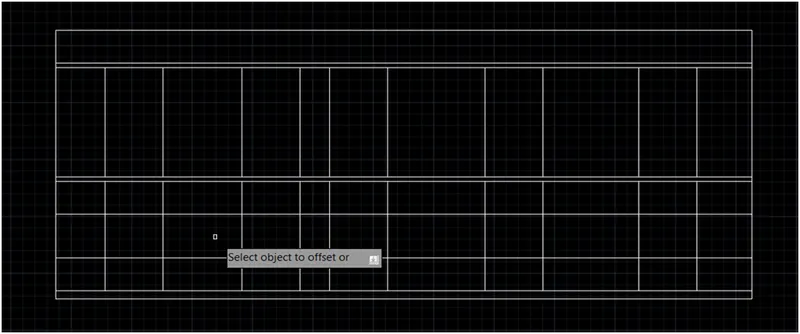
45.After the creating door window out line create a top slab of the door and window or cantilever
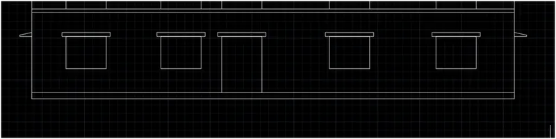
46.Then create a panel of the door and window and hatch the door and window and their cantilever slab
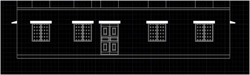
46.Draw the first floor as same as ground floor and offset 2’6” as parapet wall and top slab 3’ parapet wall and also create a tower portion and hatch the all portions as shown in the drawing
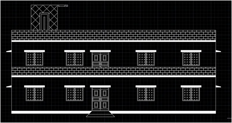
47.After creating a elevation we go for the beam plan of the drawing. create the outline of the drawing
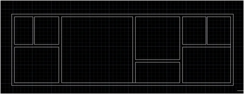
48.Then create a column 1’,9” Then place the intersection line or walls of the plan
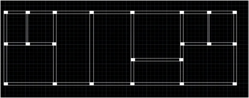
49.Then draw the center line of the walls
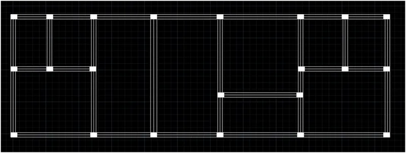
50.Then give the names of the beam and plan name
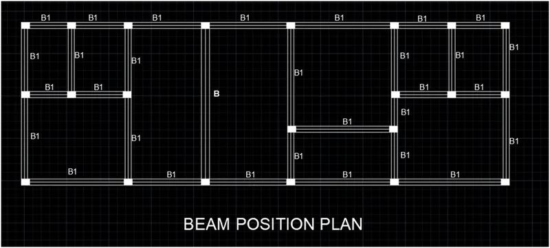
51.Ater creating a beam plan go for the column position plan copy the beam plan and delete the all lines
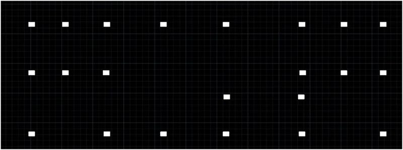
52.Then join the columns at mid to mid points as shown in the figure
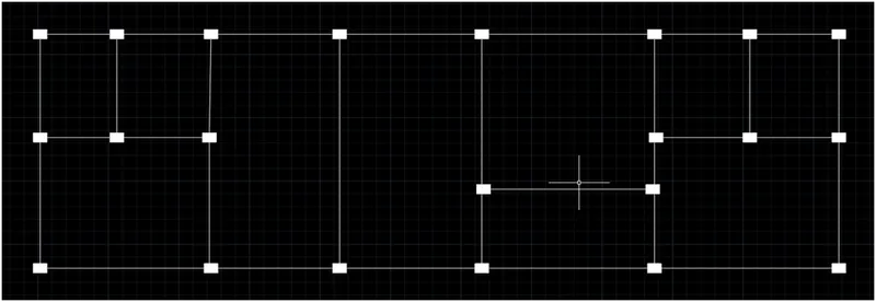
53.Go for the dimension and give the dimension of the drawing
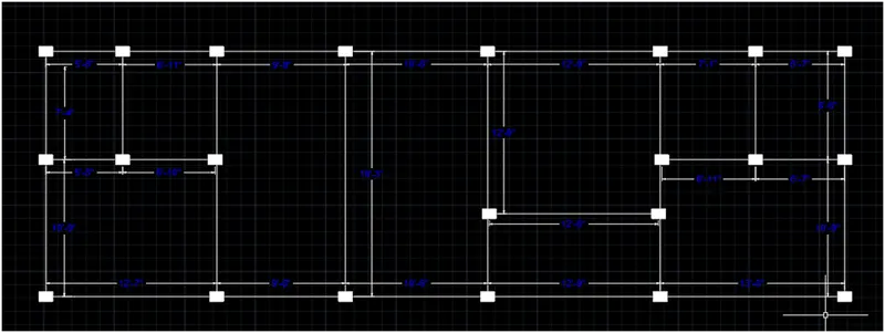
54.Give the column numbers of the plan and give the name of the plan
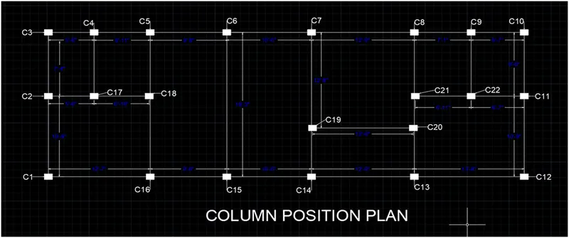
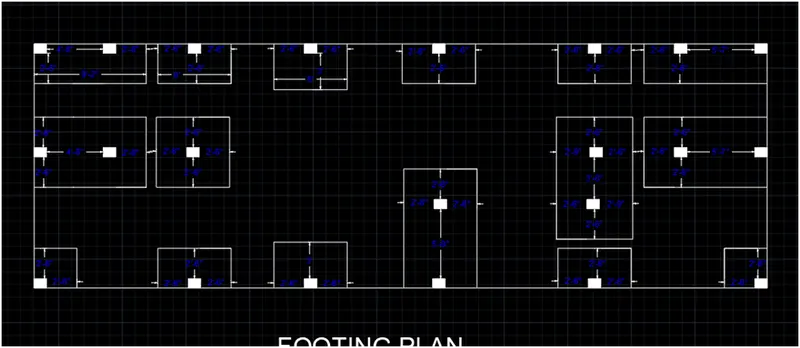
55.After creating a column position plan we go for the footing plan copy the column potion plan and delete a line and join the outer line as shown in the figure
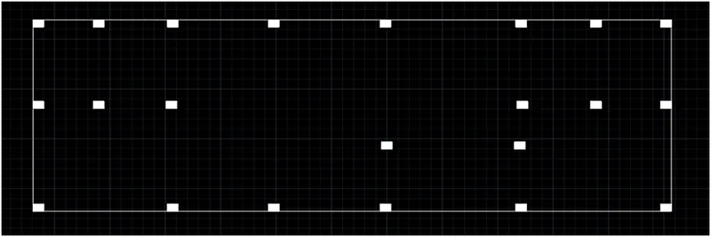
56.Then create a footing line as nominal dimension
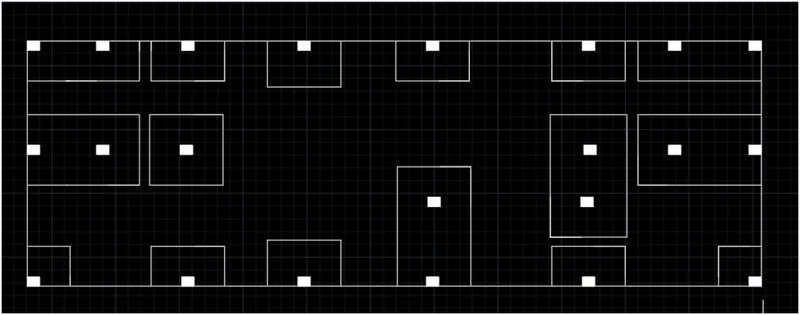
57.Give the dimension of the size of the footing
RESULT: I will draw the all drawing with any difficulty