Project 1 _Creating an Architectural plan for the provided plot size and develop relevant basic structural drawings
ANSWER -
AIM :
Aim of this project is to design and draw a layout of residential building including architectural & Structural drawings such as Floor Plan, Elevations, Section, Column & Beam Details & Footing Plan for better understanding & Execution of the drawing using Autocad.
INTRODUCTION :
- It is essential to provide all the drawings in detail in any project so that contractor can understand the drawing and can properly execute the given details on site.
- Architectural drawinngs include Floor Plan, Elevations, Section, Door/Window Schedule etc.
- Structural drawings include Centreline drawing, Column & Beam Details & Footing Plan etc.
- Designer should put enough information on the provided design for better estimation of the material required and for quality execution of the project.
- Using different color code can help understand the contractor different objects in the drawing.
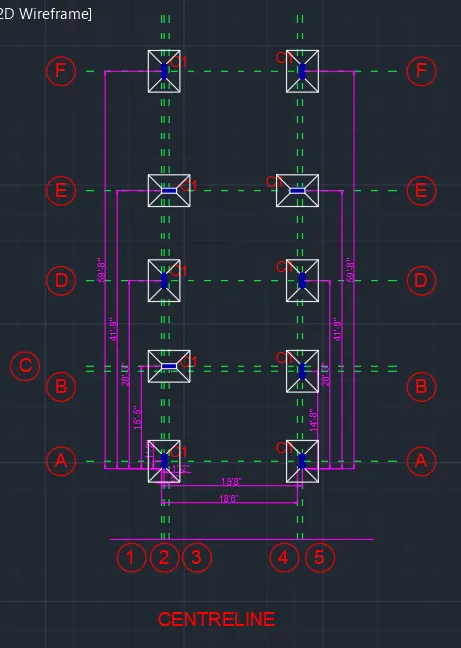
CENTRELINE PLAN :
Procedure :
- Turn on Autocad.
- Add 5 Layers separatey for Foundation, Columns, Centreline, Dimension & Texts.
- Open Layer for Centreline.
- Change the Linetype for centreline.
- Change the Layer color so as to separate the centreline from the figure.
- Draw the lay out of Centreline with the assumed dimensions in the figure using Line, Offset, Trim, Extend etc commands.
- Change the layer to Columns.
- Change the Layer color so as to separate the Columns from the figure.
- Add Columns as in the figure.
- Once all Columns are added in the figure, change the layer to the Foundation.
- Change the Layer color so as to separate the Foundation from the figure.
- Draw the lay out of Foundation with the assumed dimensions in the figure using Line, Offset, Trim, Extend etc commands.
- Once the Foundation is drawn, change the layer to the dimensions.
- Change the Layer color so as to separate the dimensions from the figure.
- Provide all the neccessary dimensions for the figure.
- Once the dimensions are provided, change the layer to the Texts.
- Change the Layer color so as to separate the Texts from the figure.
- Provide all the neccessary texts in the figure.
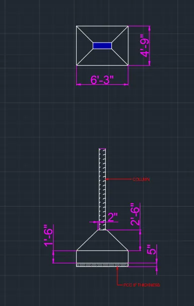
FOOTING DETAILS :
Procedure :
- Turn on the Autocad.
- Draw the given section with the use of Line, Devide, Offset & Trim command.
- Use Hatch command to separate the area as in the figure.
- Use Leader command to provide the given arrows in the figure and change the size of the arrow from dimension style if required.
- Copy, Move and Edit the texts as per the requirements.
- Use linear dimension to provide the given dimensions.
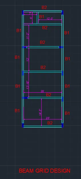
BEAM DETAILS :
Procedure :
- Make a Layer for Beams.
- Draw the Beam Plan using Layer for Beam with the use of Line, Devide, Offset & Trim command.
- Change the layer to Columns.
- Change the Layer color so as to separate the Columns from the figure.
- Add Columns as in the figure.
- Once the Foundation is drawn, change the layer to the dimensions.
- Change the Layer color so as to separate the dimensions from the figure.
- Provide all the neccessary dimensions for the figure.
- Use linear dimension to provide the given dimensions.
- Once the dimensions are provided, change the layer to the Texts.
- Change the Layer color so as to separate the Texts from the figure.
- Provide all the neccessary texts in the figure.
- Write the given details using Dtext command.
- Copy, Move and Edit the texts as per the requirements.
COLUMN & BEAM DETAILS :
Procedure :
- Draw the table with the use of Line, Devide, Offset & Trim command.
- Write the given details using Dtext command in text layer.
- Copy, Move and Edit the texts as per the requirements.
- Draw the Column & Beam stirrups detail as shown in the figure using Line, Point command.
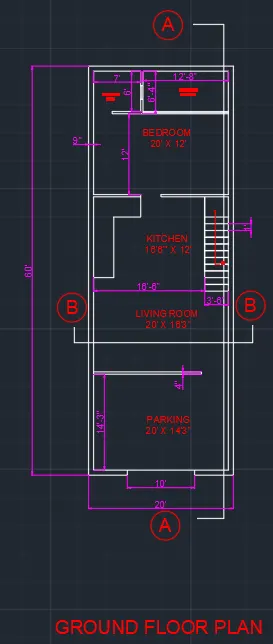
GROUND FLOOR PLAN :
Procedure :
- Open Layer for Walls.
- Draw the lay out of walls & stairs with the given dimensions in the figure using Line, Offset, Trim, Extend etc commands.
- Change Linetype to draw outer wall of the given floor plan.
- Leave space for doors & windows.
- Change the layer to doors & windows.
- Add doors and windows as in the figure.
- Once the all doors and windows are added in the figure, change the layer to the Dimension.
- Change the Layer color so as to separate the dimensions from the figure.
- Provide all the neccessary dimensions for the figure.
- Once the dimensions are provided, change the layer to the Texts.
- Change the Layer color so as to separate the Texts from the figure.
- Provide all the neccessary texts in the figure.
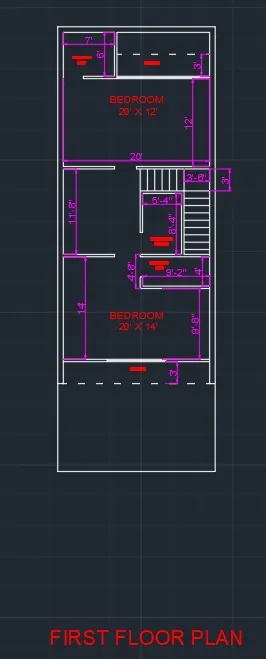
FIRST FLOOR PLAN :
Procedure :
- Open Layer for Walls.
- Draw the lay out of walls & stairs with the given dimensions in the figure using Line, Offset, Trim, Extend etc commands.
- Change Linetype to draw outer wall of the given floor plan.
- Leave space for doors & windows.
- Change the layer to doors & windows.
- Add doors and windows as in the figure.
- Once the all doors and windows are added in the figure, change the layer to the Dimension.
- Change the Layer color so as to separate the dimensions from the figure.
- Provide all the neccessary dimensions for the figure.
- Once the dimensions are provided, change the layer to the Texts.
- Change the Layer color so as to separate the Texts from the figure.
- Provide all the neccessary texts in the figure.
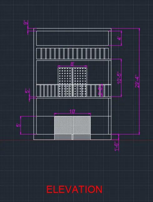
ELEVATIONS :
Procedure :
- Open Layer for Walls.
- Draw the lay out of walls & stairs with the given dimensions in the figure using Line, Offset, Trim, Extend etc commands.
- Change Linetype to draw outer wall of the given floor plan.
- Leave space for doors & windows.
- Change the layer to doors & windows.
- Add doors and windows as in the figure.
- Once the all doors and windows are added in the figure, change the layer to the Dimension.
- Change the Layer color so as to separate the dimensions from the figure.
- Provide all the neccessary dimensions for the figure.
- Once the dimensions are provided, change the layer to the Texts.
- Change the Layer color so as to separate the Texts from the figure.
- Provide all the neccessary texts in the figure.
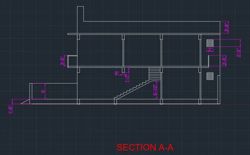
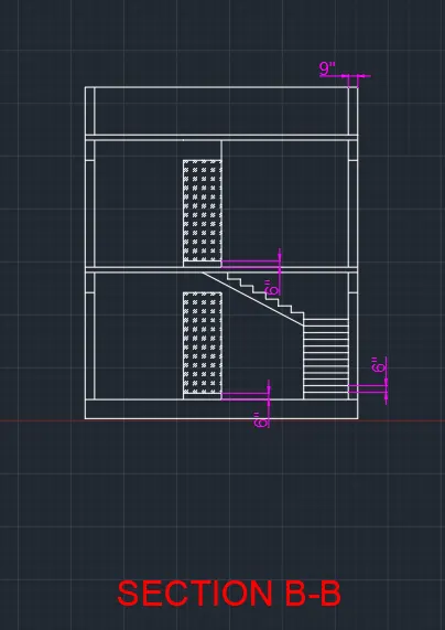
SECTIONS :
Procedure :
- Open Layer for Walls.
- Draw the lay out of walls & stairs with the given dimensions in the figure using Line, Offset, Trim, Extend etc commands.
- Change Linetype to draw outer wall of the given floor plan.
- Leave space for doors & windows.
- Change the layer to doors & windows.
- Add doors and windows as in the figure.
- Once the all doors and windows are added in the figure, change the layer to the Dimension.
- Change the Layer color so as to separate the dimensions from the figure.
- Provide all the neccessary dimensions for the figure.
- Once the dimensions are provided, change the layer to the Texts.
- Change the Layer color so as to separate the Texts from the figure.
- Provide all the neccessary texts in the figure.