Project 1 _Creating an Architectural plan for the provided plot size and develop relevant basic structural drawings
AIM:
Creating an Architectural plan for the provided plot size and develop relevant basic structural drawings
Design and Draft a layout of a residential building with the following details:
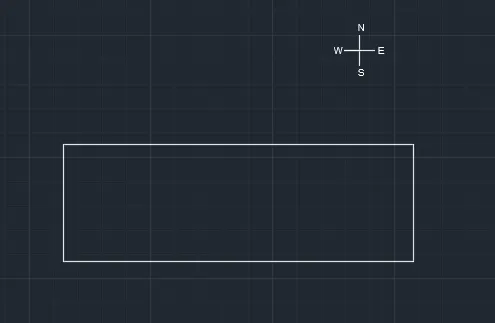
a. Plot Size: 60’x20’(18.3m x6m)
b. Orientation- Facing East
c. Develop the following: 1. Architectural Drawing (Floor Plan, Elevations, and Sections) 2. Structural Drawing (Column, Bean, Footing Plan)
INTRODUCTION:
AutoCAD is a commercial computer-aided design (CAD) and drafting software application. Developed and marketed by Autodesk,[1] AutoCAD was first released in December 1982 as a desktop app running on microcomputers with internal graphics controllers.[2] Before AutoCAD was introduced, most commercial CAD programs ran on mainframe computers or minicomputers, with each CAD operator (user) working at a separate graphics terminal.[3] AutoCAD is also available as mobile and web apps.
AutoCAD is used in industry, by architects, project managers, engineers, graphic designers, city planners and other professionals. It was supported by 750 training centers worldwide in 1994.[1]
In this project i used various commands such as line ,Trim,Hatch,MText,TextEDit,Layers,Dimension style & various commands.
PROCEDURE:
Open AUTOCAD
Type units in command section & give enter change type to Architectural & Precision to 0'-0",Units to inches give ok.
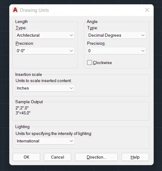
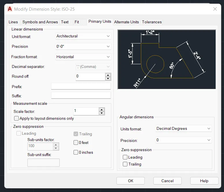
Type D given enter change the unit format to Architectural & precision to 0'-0" set current & close.
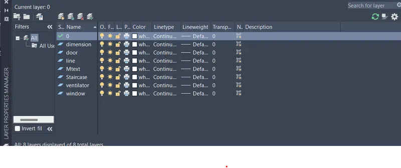
Go to layer properties >create new layers>name the layers for reference>close.
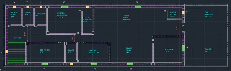
Using line command create a plot boundaary of 60'*20'
Draw direction lines for reference
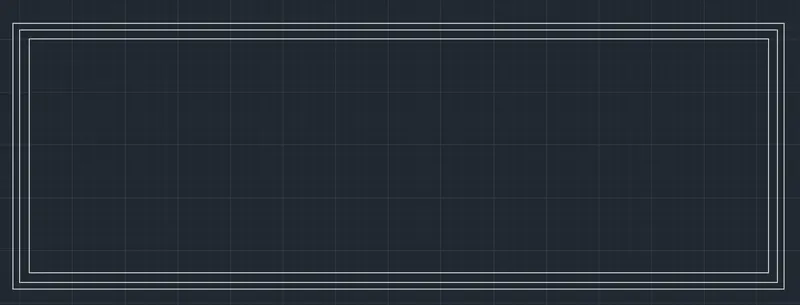
Outer wall of thickness 9"& inner wall of thickness 4" is provided.
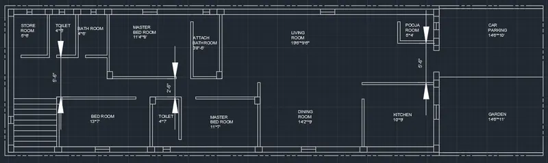
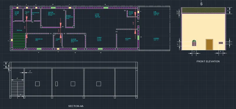
Now using line,Fillet,Trim ,Extend and various commands i have created a plan.
The plan is as per vaasthu shastra
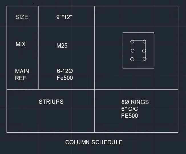
Using line command i have created columns of sizes 9"*12" copy pasted wherever required.
Stairs are provided using line & offset command Tread of 1' & Riser 9"
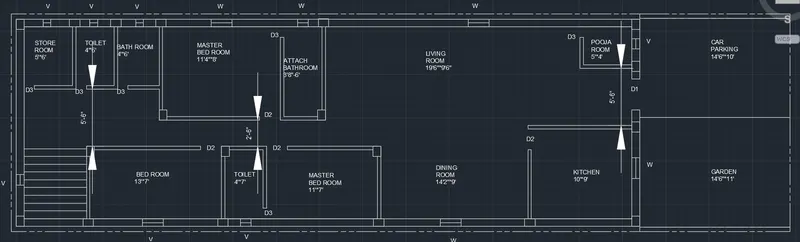
Doors & windows are provided at required places
Changed the compound wall line type to Acad-ISO09W100
Using line & offset command compound wall of car parking & garden is created to a thickness of 5"
The dimension are mentioned using DTEXT command.
Used MTEXT to indicate the rooms.
Extra spaces are mentioned using Arrow marks
Alloted doors ,windows & ventilators where required & mentioned as V,W,D1,D2,D3
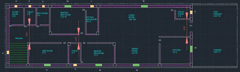
Using hatch commands columns are filled with AR-CONC.
From layer properties colour of window,ventilator,wall,staircase,Dimesnion,MTEXT colour is changed
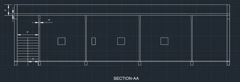
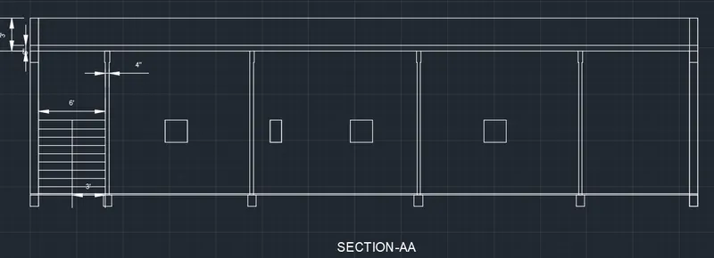
Using the commanmd XL(VERTICAL),XL(HORIZONTAL),TRIM,OFFSET i had drawn the elevation SECTION AA
Trim the unwanted lines.
Dimensions are imdicated using DIM-TEXT command.
Words are type using MTEXT.
Front elevation is created using XL-VER,XL-HOR,TRIM,HATCH command
Window dimension 2'*2' & arc is used in window ,ventilator dimension,door dimension3'*5'
Dimensions are mentioned using DIM-STYLE
Text created using DIMTEXT command
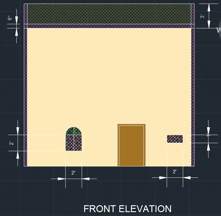
The following imagess shows the Floor plan,Section-AA & Front elevation.
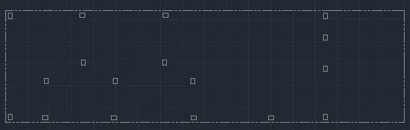
Now using copy command ,copy all the columns & plot boundary ,paste it all above the floor plan.
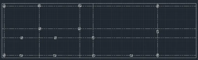
Hatch the columns using hatch command
Turn on midpoint from snap settings & draw grid lines using command XV(VER) & XL(HOR)
`
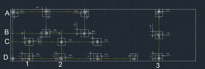
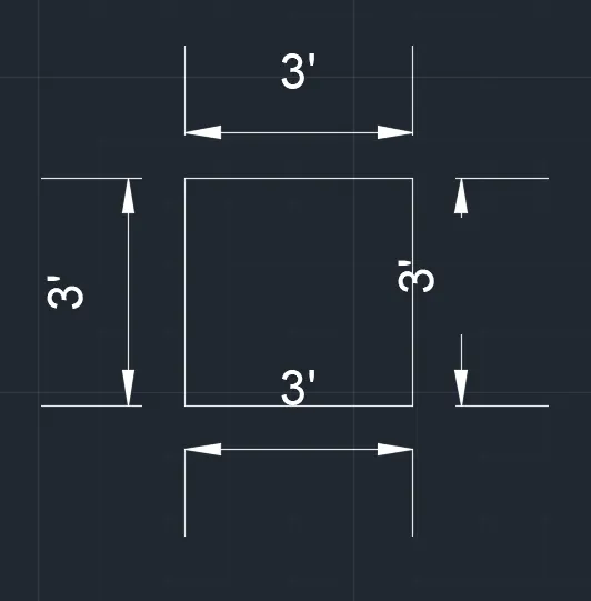
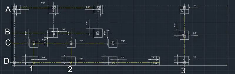
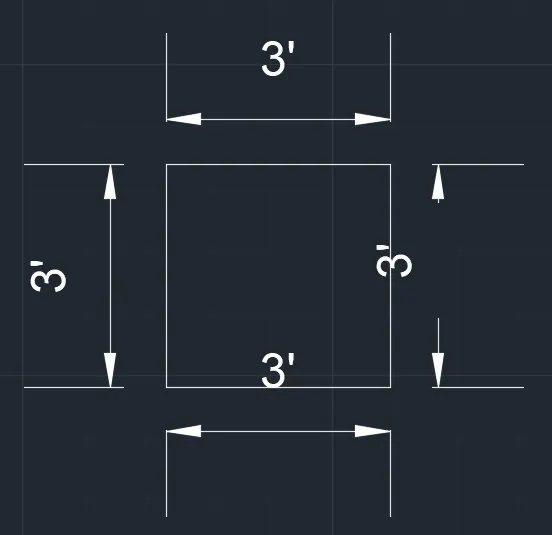
Using rectangle command the sqaure footing of size 3'*3' is provided for all columns
Turn on the midpoint in snap settings ,copy paste created square footing to all the columns
Change the lines into dash type from the By-layer properties
Mark the dimesnison of the footing using DIM STYLE command
Changing the colour of the grid lines for clear visibility
Mentional horizontal grid lines as A,B,C,D & Vertical grid lines 1,2,3
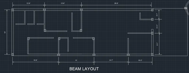
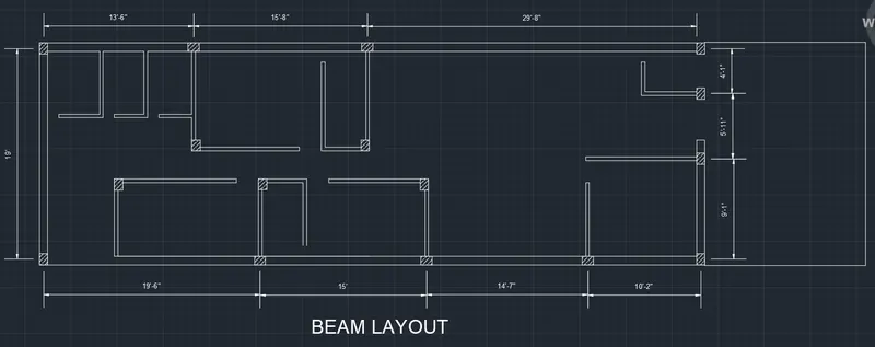
Using copy command all columns & beams are pasted.
Using DIM-LINE command centre to centre distance between each column is mentioned
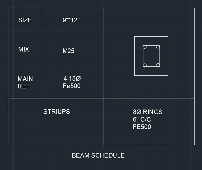
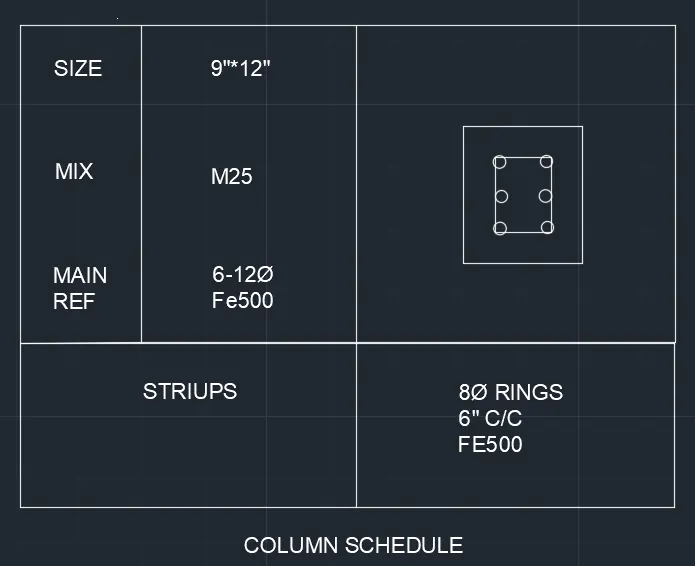
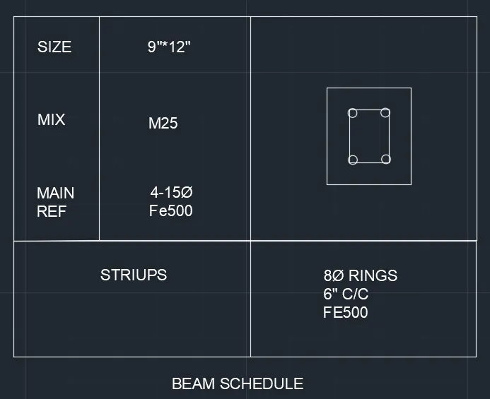
Using line ,circle,MTEXT command Column schedule,Beam schedule & Footing where created.
RESULT: