Project 1 - Controlling a DC motor using PWM and monitoring its Running status
Project 1 - Controlling a DC motor using PWM and monitoring its Running status
- Overview of the Project:
- Implement a system on the simulator for controlling a DC motor using L293 motor driver, monitor its status and print the running status of motor on the LCD Display.
- Goals:
- Implement a system on simulator for Controlling the DC motor using L293 motor driver.
- Displaying the running status of DC motor on the LCD display.
- Key Highlights of the Project:
- The DC motor can be controlled by using L293 motor driver.
- The speed of a DC motor can be controlled by varying its input voltage, for doing this is to use PWM (Pulse Width Modulation).
- L293D IC is a typical Motor Driver IC which allows the DC motor to drive on any direction.
- Deliverables of this project:
- Implement the system for controlling DC motor.
- Controlling the speed of the DC motor using PMW.
- Displaying the present running status of DC machine on LCD display.
- Expected Outcomes:
- Implement a system on simulator to control a DC motor using PMW
- Monitoring the running status of the DC motor using L293 motor driver which allows the DC motor todrive on any direction.
- Running status i.e. on which direction the DC motor is running is to be displayed on the LCD screen.
Title: Controlling a DC Motor with L293 Motor Driver and Monitoring its Running Status
Aim:
The aim of this project is to implement a system on the simulator to control a DC motor using PWM with the L293 motor driver. The project also involves monitoring the running status of the DC motor and displaying it on an LCD screen.
Components Used:
- AVR microcontroller (ATmega32)
- L293 motor driver IC
- DC motor
- Push button switch
- LCD display (16x2)
- 5V power supply
- Resisters
Circuit Diagram:
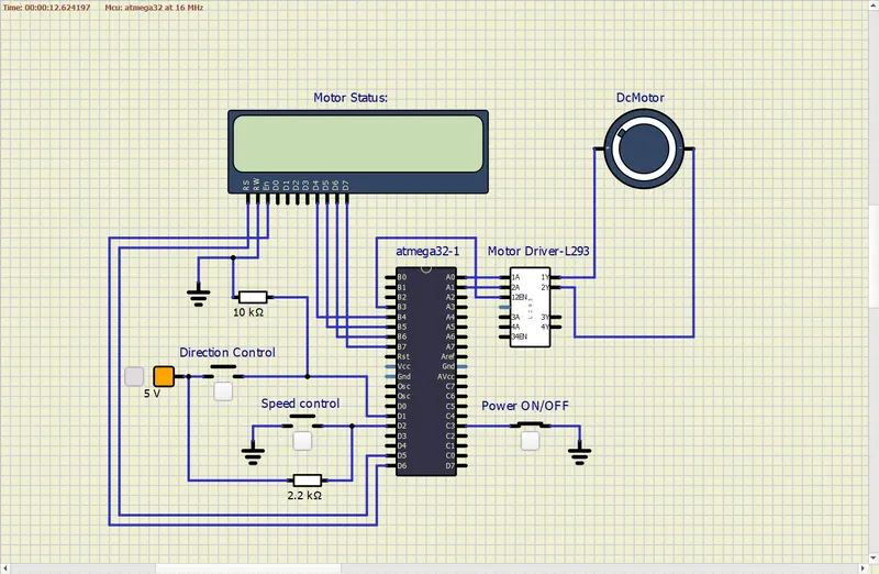
Code:
#include <avr/io.h>
#define F_CPU 16000000L
#include "avr/interrupt.h"
#include <util/delay.h>
#define sw_dir (PIND & (1<<1))
#define pw (PINC & (1<<3))
// LCD connections and commands
#define lcd_port PORTB
#define RS_high PORTD |= (1<<5)
#define RS_low PORTD &=~ (1<<5)
#define EN_high PORTD |= (1<<6)
#define EN_low PORTD &=~ (1<<6)
// LCD specific commands
#define LCD_LINE_1 0x80
#define LCD_LINE_2 0xC0
// Variable to store duty cycle
unsigned char i;
// Function to send a command to the LCD
void lcd_cmd(char cmd)
{
lcd_port = (cmd & 0xF0); // Send higher 4 bits of the command
RS_low; // Set RS pin low (command mode)
EN_low; // Set EN pin low
_delay_ms(1); // Delay to ensure command is processed
EN_high; // Set EN pin high to process the command
lcd_port = ((cmd << 4) & 0xF0); // Send lower 4 bits of the command
RS_low; // Set RS pin low
EN_low; // Set EN pin low
_delay_ms(1); // Delay to ensure command is processed
EN_high; // Set EN pin high to process the command
}
// Function to send data to the LCD
void lcd_data(char data)
{
lcd_port = (data & 0xF0); // Send higher 4 bits of the data
RS_high; // Set RS pin high (data mode)
EN_low; // Set EN pin low
_delay_ms(1); // Delay to ensure data is processed
EN_high; // Set EN pin high to process the data
lcd_port = ((data << 4) & 0xF0); // Send lower 4 bits of the data
RS_high; // Set RS pin high (data mode)
EN_low; // Set EN pin low
_delay_ms(1); // Delay to ensure data is processed
EN_high; // Set EN pin high to process the data
}
// Function to initialize the LCD
void lcd_init()
{
// Initialize LCD in 4-bit mode with 2 lines and 5x8 font size
lcd_cmd(0x28);
_delay_ms(5);
lcd_cmd(0x02); // Return cursor to home position
_delay_ms(5);
lcd_cmd(0x01); // Clear display
_delay_ms(5);
lcd_cmd(0x0C); // Display ON, cursor OFF
_delay_ms(5);
}
// Function to display a string on the LCD
void lcd_string(const char* str)
{
while (*str)
{
// Send each character of the string to the LCD
lcd_data(*str++);
}
}
// Function to configure the adc value
int adc_read(char channel)
{
unsigned int a, result;
ADMUX = channel; // Select ADC channel
ADCSRA = 0X80; // Enable ADC, Start conversion, Enable ADC interrupt
ADCH = 0X00; // Clear ADC high value
ADCL = 0x00; // Clear ADC low value
ADCSRA |= (1<<6); // Start the conversion
// Wait for the conversion to complete
while((ADCSRA & 0x40) != 0);
a= ADCL; // Read ADC low value
result = ADCH; // Read ADC high value
result = result<<8; // Read ADC high value
// Combine high and low values to get the result
result = result | a ;
return result;
}
//main function
int main(void)
{
// Set data direction for LCD and control pins
DDRB = 0xFF; // All 8 pins of PORTB are set as output
DDRA |= ((1 << 0) | (1 << 1)); // A0 & A1 pins set as output
DDRD &= ~(1 << 1); // D1 pin set as input
DDRD &= ~(1 << 2); // D2 pin set as input
DDRD |= (1 << 5); // D5 pin set as output
DDRD |= (1 << 6); // D6 pin set as output
DDRC &= ~(1 << 3); // C3 pin set as input
PORTD |= (1 << 2); // Enable internal pull-up resistor for D2
PORTC |= (1 << 3); // Enable internal pull-up resistor for D3
i = 64; // Initialize i=64 for 25% duty cycle
TCCR0 = 0x61; //Non-Inverting mode, PWM phase correct mode
GICR = (1 << INT0); // Enable external interrupt INT0
MCUCR = 0x02; // Set interrupt INT0 to be triggered on falling edge
sei(); // Enable global interrupt
lcd_init();
while (1)
{
while (pw == 0)
{
// Continue till the push button is released
if (sw_dir == 0)
{
// Set appropriate motor direction pins
PORTA = 0b00000001;
lcd_cmd(LCD_LINE_1);
lcd_string("->Motor ON-CL "); // Display message
}
else
{
// Set appropriate motor direction pins
PORTA = 0b00000010;
lcd_cmd(LCD_LINE_1);
lcd_string("->Motor ON-ACL "); // Display message
}
OCR0 = i;
}
PORTA = 0x00; // Turn off motor
lcd_cmd(LCD_LINE_1);
lcd_string("->Motor TURN OFF "); // Display message on LCD
}
}
ISR(INT0_vect)
{
// Increase duty cycle when the external interrupt occurs
i = i + 22;
}
Code Explanation:
The code starts by including necessary libraries and defining constants for the pins and commands used in the program. It then initializes the ADC and sets up the LCD display. The main function configures the ports and pins for motor control, external interrupt, and ADC.
The main loop continuously monitors the push button state and the direction switch. When the push button is pressed, the motor starts running in the specified direction, and the duty cycle is adjusted based on the external interrupt.
When the push button is released, the motor stops, and the LCD displays the status accordingly.
Explanation of Registers Used in the Program:
- DDRB, DDRA, DDRD, DDRC: Data Direction Registers for configuring the direction of PORTB, PORTA, PORTD, and PORTC pins.
- PORTD: Used for enabling internal pull-up resistors for D2 and D3 pins (push button and direction switch inputs).
- TCCR0: Timer/Counter Control Register for Timer0 configuration (PWM settings).
- GICR: General Interrupt Control Register for enabling external interrupts.
- MCUCR: MCU Control Register for configuring external interrupt behavior (trigger on falling edge).
- ADCSRA, ADMUX: ADC Control and Status Registers for configuring and starting ADC conversion.
Output with All Possible Conditions:
- When the push button is pressed and the direction switch is in one position, the motor starts running in the specified direction with a duty cycle proportional to the external interrupt count. The LCD displays the running status.
CLOCKWISE:
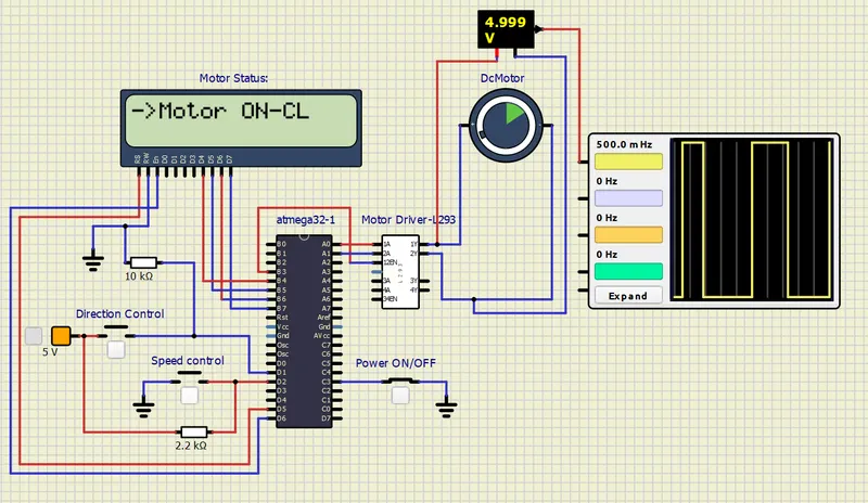
- When the push button is pressed and the direction switch is in the other position, the motor starts running in the opposite direction with a duty cycle proportional to the external interrupt count. The LCD displays the running status.
ANTI CLOCKWISE:
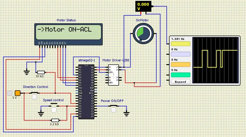
- When the push button is released, the motor stops, and the LCD displays the "Motor TURN OFF" message.
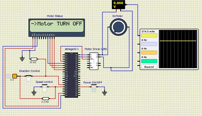
Result:
The implemented system successfully controls the DC motor using PWM and the L293 motor driver. The motor can be started, stopped, and its speed can be adjusted using the push button and direction switch. The running status of the motor (clockwise or anti-clockwise) is displayed on the LCD.
Conclusion:
The project successfully demonstrates the control of a DC motor using PWM and the L293 motor driver. The system allows the user to start and stop the motor, adjust its speed, and monitor its running status. This project can be useful for various applications that involve motor control and monitoring.
For verification purposes here I have attached the execution video link to access: https://drive.google.com/file/d/1Fx0WJaOe3cckaFBvl52XRkn6S3p8UXYs/view?usp=sharing
For all project files link to access: https://drive.google.com/drive/folders/1G6jU8BRNTHHw1VddxjpcVg5gSYaCW_Mx?usp=sharing