Project 1 - Controlling a DC motor using PWM and monitoring its Running status
FUNTIONING OF LOGIC:
- Rotaional Direction Control. "SPEED_DIRECTION"
- PWM Control. "SPEED_SPEED"
- On/OFF swtich. "SPEED_POWER"
The theoretical logic behind the provided code can be summarized as follows:
-
Initialization: The code begins by including the necessary header files and defining constants for the microcontroller's frequency and various input/output pins. It also declares a global variable
motorSpeedto store the speed of the motor. -
LCD Functions: Several functions are defined to interact with the LCD display.
lcdSendCommand()sends commands to the LCD,lcdSendData()sends data to be displayed on the LCD,lcdInit()initializes the LCD, andlcdSetCursorPosition()sets the cursor position on the LCD.lcdPrint()is a convenience function that combines cursor positioning and data sending to display text on the LCD. -
Main Function: The
main()function is the entry point of the program. It sets the data direction registers for the required ports, initializes the LCD, and configures the timer and interrupts. -
Motor Control Loop: The main program loop starts with a
while (1)loop, which runs indefinitely. Within this loop, there is a nested loop that checks the state of the power switch (SWITCH_POWER). If the power switch is on (pressed), the motor is considered off, and a corresponding message is displayed on the LCD. If the power switch is off (released), the nested loop continues to check the direction switch (SWITCH_DIRECTION). -
Motor Direction and Speed Control: If the direction switch indicates clockwise (
SWITCH_DIRECTION == 0), the motor is set to rotate clockwise, and the LCD displays the running status as "Motor is Running" and "Clockwise". If the direction switch indicates anticlockwise, the motor is set to rotate anticlockwise, and the LCD displays the appropriate running status. The motor speed is controlled using PWM (Pulse Width Modulation) by adjusting the value ofOCR0(output compare register). ThemotorSpeedvariable is incremented in response to an external interrupt (INT0) triggered by the user. -
Interrupt Service Routine: The
ISR(INT0_vect)function is the interrupt service routine associated with the external interrupt INT0. In this case, it is used to increase the motor speed by 20 units when the external interrupt is triggered.
The code continuously monitors the state of the switches and updates the motor control and LCD display accordingly, providing a means to control the motor's direction and speed and visualize the motor's status on the LCD.
SIMULATION IMAGES:
OFF STATE:
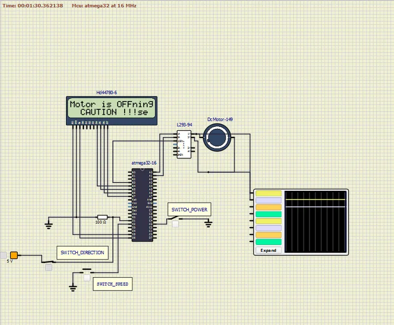
Clockwise Running State:
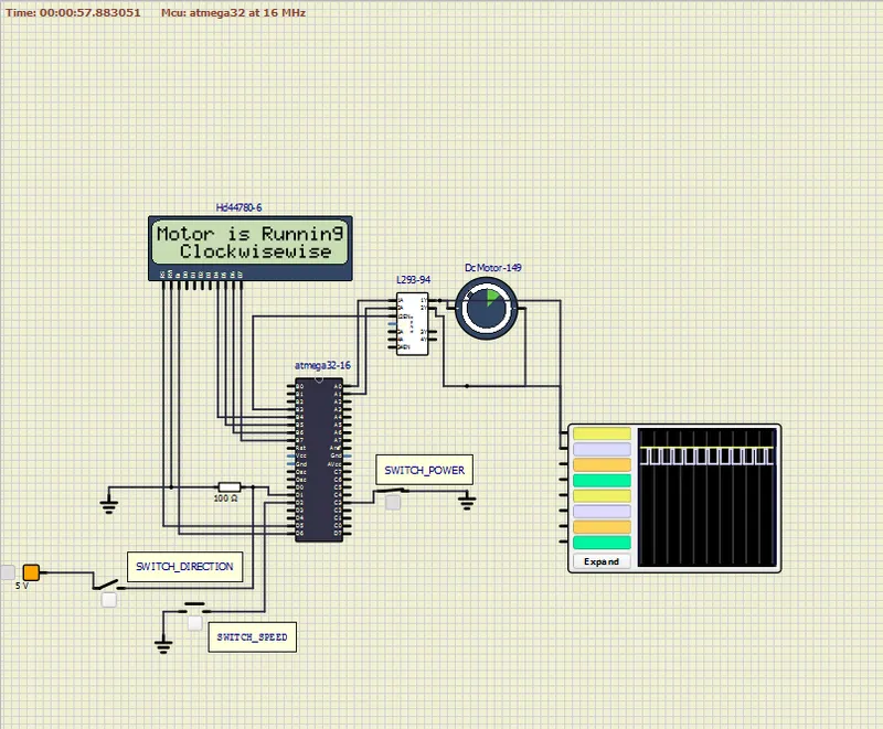
Anti-Clockwise State:
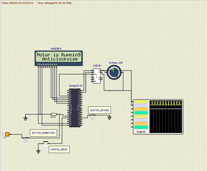
SIMULATION CIRCUIT:
circuit.simu
CODE:
#include <avr/io.h>
#define F_CPU 16000000L
#include <avr/interrupt.h>
#include <util/delay.h>
#define SWITCH_DIRECTION (PIND & (1 << PD1))
#define SWITCH_SPEED (PIND & (1 << PD2))
#define SWITCH_POWER (PINC & (1 << PC3))
#define LCD_DATA_PORT PORTB
#define LCD_RS_HIGH PORTD |= (1 << PD5)
#define LCD_RS_LOW PORTD &= ~(1 << PD5)
#define LCD_EN_HIGH PORTD |= (1 << PD6)
#define LCD_EN_LOW PORTD &= ~(1 << PD6)
unsigned char motorSpeed;
void lcdSendCommand(char cmd)
{
LCD_DATA_PORT = (cmd & 0xF0); // Sending higher nibble
LCD_RS_LOW; // Command mode
LCD_EN_LOW;
_delay_ms(1);
LCD_EN_HIGH;
LCD_DATA_PORT = ((cmd << 4) & 0xF0); // Sending lower nibble
LCD_RS_LOW;
LCD_EN_LOW;
_delay_ms(1);
LCD_EN_HIGH;
}
void lcdSendData(char data)
{
LCD_DATA_PORT = (data & 0xF0); // Sending higher nibble
LCD_RS_HIGH; // Data mode
LCD_EN_LOW;
_delay_ms(1);
LCD_EN_HIGH;
LCD_DATA_PORT = ((data << 4) & 0xF0); // Sending lower nibble
LCD_RS_HIGH;
LCD_EN_LOW;
_delay_ms(1);
LCD_EN_HIGH;
}
void lcdInit()
{
lcdSendCommand(0x02); // Return home
_delay_ms(5);
lcdSendCommand(0x01); // Clear display
_delay_ms(5);
lcdSendCommand(0x0C); // Display ON, Cursor OFF
_delay_ms(5);
lcdSendCommand(0x06); // Entry mode: Increment cursor
_delay_ms(5);
lcdSendCommand(0x80); // Force cursor to beginning of the 1st line
_delay_ms(5);
lcdSendCommand(0x28); // 4-bit mode, 2 lines, 5x7 font
_delay_ms(5);
}
void lcdSetCursorPosition(char x, char y)
{
if ((x < 1 || x > 2) || (y < 1 || y > 16))
{
x = 1;
y = 1;
}
if (x == 1)
{
lcdSendCommand(0x7F + y);
}
else
{
lcdSendCommand(0xBF + y);
}
}
void lcdPrint(char x, char y, const char *str)
{
lcdSetCursorPosition(x, y);
while (*str)
{
lcdSendData(*str);
str++;
}
}
int main()
{
DDRB = 0xFF; // Set PORTB as output
DDRA |= (1 << PA0) | (1 << PA1); // Set PA0 and PA1 as output
DDRD &= ~(1 << PD1); // Set PD1 as input
DDRD &= ~(1 << PD2); // Set PD2 as input
DDRD |= (1 << PD5) | (1 << PD6); // Set PD5 and PD6 as output
DDRC &= ~(1 << PC3); // Set PC3 as input
PORTD |= (1 << PD2); // Enable internal pull-up resistor for PD2
PORTC |= (1 << PC3); // Enable internal pull-up resistor for PC3
motorSpeed = 64; // Initial motor speed
TCCR0 = 0x61; // Timer0: Phase Correct PWM, F_CPU/64 as frequency
GICR = (1 << INT0); // Enable INT0 external interrupt
MCUCR = 0x02; // INT0 falling edge interrupt
sei(); // Enable global interrupts
lcdInit();
while (1)
{
while (SWITCH_POWER == 0)
{
if (SWITCH_DIRECTION == 0)
{
PORTA = 0b00000001;
lcdPrint(1, 1, "Motor is Running");
lcdPrint(2, 3, "Clockwise");
}
else
{
PORTA = 0b00000010;
lcdPrint(1, 1, "Motor is Running");
lcdPrint(2, 3, "Anticlockwise");
}
OCR0 = motorSpeed;
}
PORTA = 0x00;
lcdPrint(1, 1, "Motor is OFF");
lcdPrint(2, 3, "CAUTION !!!");
}
}
ISR(INT0_vect)
{
motorSpeed += 20;
}
AVR PROJECT FILE:
Project_1_atmega328.zip