Project 1 - Controlling a DC motor using PWM and monitoring its Running status
Aim: To Implement a system on the simulator for controlling a DC motor using the L293 motor driver, monitor its status and print the running status of motor on the LCD Display.
General Description:
- The direction of the DC motor can be controlled by using the L293 motor driver. L293D IC is a typical Motor Driver IC that allows the DC motor to drive in any direction.
- The speed of a DC motor can be controlled by varying its input voltage, for doing this we have used PWM (Pulse Width Modulation).
CODE:
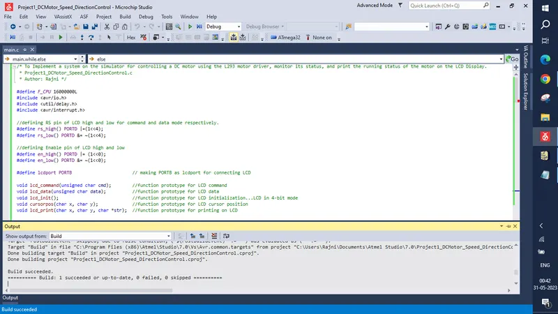
/* To Implement a system on the simulator for controlling a DC motor using the L293 motor driver, monitor its status, and print the running status of the motor on the LCD Display.
 * Project1_DCMotor_Speed_DirectionControl.c
 * Author: Rajni */

#define F_CPU 16000000L
#include <avr/io.h>
#include <util/delay.h>
#include <avr/interrupt.h>

//defining RS pin of LCD high and low for command and data mode respectively.
#define rs_high() PORTD |=(1<<4);
#define rs_low() PORTD &= ~(1<<4);

//defining Enable pin of LCD high and low
#define en_high() PORTD |= (1<<0);
#define en_low() PORTD &= ~(1<<0);

#define lcdport PORTB						// making PORTB as lcdport for connecting LCD

void lcd_command(unsigned char cmd);		//function prototype for LCD command
void lcd_data(unsigned char data);			//function prototype for LCD data
void lcd_init();							//function prototype for LCD initialization...LCD in 4-bit mode
void cursorpos(char x, char y);				//function prototype for LCD cursor position
void lcd_print(char x, char y, char *str);  //function prototype for printing on LCD

unsigned char i;							//global variable for varying duty cycle i.e. speed of the dc motor
unsigned int flag = 0;						// global variable for changing the direction of the motor from clockwise to anticlockwise and vice-versa

void lcd_command(unsigned char cmd)
{
	rs_low();						//RS = 0 for command
	lcdport = cmd & 0xf0;			// send upper nibble
	en_high();						//EN = 1
	_delay_ms(1);
	en_low();						//EN = 0
	lcdport = cmd << 4 ;			// send low nibble
	en_high();						//EN = 1
	_delay_ms(1);
	en_low();						//EN = 0
}
void lcd_data(unsigned char data)
{
	rs_high();						//RS = 1 for data
	lcdport = data & 0xf0;			// send upper nibble
	en_high();						//EN = 1
	_delay_ms(1);
	en_low();						//EN = 0
	lcdport = data << 4;			//send low nibble
	en_high();						//EN = 1
	_delay_ms(1);
	en_low();						//EN = 0
}
void lcd_init()
{
	DDRB = 0xff;		//  output Port B for LCD
	lcd_command(0x33);
	_delay_ms(1);
	lcd_command(0x32);
	_delay_ms(1);
	lcd_command(0x28); // LCD in 4-bit mode
	_delay_ms(1);
	lcd_command(0x01); // clear screen
	_delay_ms(1);
	lcd_command(0x0c); // Display ON ,cursor OFF
	_delay_ms(1);
}
void cursorpos(char x, char y)
{
	if( (x < 1 || x > 2)  || (y < 1 || y > 16) )  // if cursor beyond 2*16, set as row 1 column 1
	{
		x = 1;
		y = 1;
	}
	if(x == 1)
	lcd_command(0x80+y);			// 1st row y th column
	else
	lcd_command(0xC0+y);			// 2nd row y th column

}
void lcd_print(char x, char y, char *str)
{
	cursorpos(x,y);
	while(*str)
	{
		lcd_data(*str);
		str++;
	}
}

int main(void)
{
	lcd_init();
	DDRC = 0xff;				//PORTC as an output port for motor via L293

	i=64;						// initially 25 % duty cycle... (25*256)/100 = 64
	OCR0 = i;					// loading 64 into output compare register for timer 0
	TCCR0 = 0x61;				// Phase Correct PWM, Non-inverted mode, no prescalar, 16 MHz crystal frequency

	DDRB |=(1<< PB3);			// PD3 as output connected to enable of L293 Device //PB3 pin OCR

	DDRD &= ~(1<<PD2);			// Make PD2 as input pin ...INT0 pin...
	PORTD |= (1<<PD2);			// Activate pull up for PD2

	DDRD &= ~(1<<PD3);			// Make PD3 as input pin ...INT1 pin...
	PORTD |= (1<<PD3);			// Activate pull up for PD3

	GICR = (1<< INT0) | (1<<INT1) ;  // Enable External Interrupts
	MCUCR = 0x02;					// Make Interrupt 0 negative edge triggered
	sei();							//enable external interrupts

	while(1)
	{
		OCR0 = i;					// to increment duty cycle i.e. to increase the speed of the dc motor

		if(flag % 2 == 0)
		{
			PORTC = 0x01;
			lcd_print(1,1,"Motor Runs in");
			lcd_print(2,1,"  Clockwise   ");
		}
		else
		{
			PORTC = 0x02;
			lcd_print(1,1,"Motor Runs in");
			lcd_print(2,1,"Anti-Clockwise");
		}
	}
	return 0;
}

ISR(INT0_vect)
{
	i = i + 10;  // to increase the speed of the dc motor by a value of 10...incrementing Output Compare Register OCR0 for timer 0
}
ISR(INT1_vect)
{
	flag++;  // to change the direction of motor
}
SimulIDE Circuit:
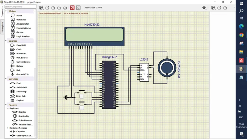
The circuit consists of:
- LCD (in 4-bit mode)
- Atmega32
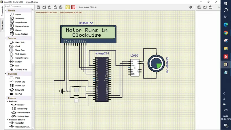
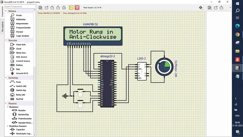
- Push Buttons - the first push button at PD2 controls the speed of the motor and the second push button at PD3 changes the direction of the motor from clockwise to anticlockwise and vice-versa.
- L293 Driver
- DC motor
- Connecting wires
- Ground
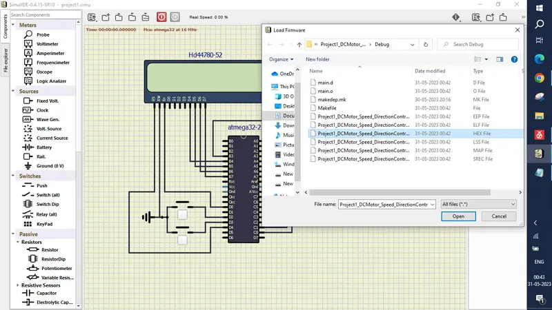
Loading the Hex file:
Running the Model/Circuit:
Initially, the motor will run in the clockwise direction as per our code.
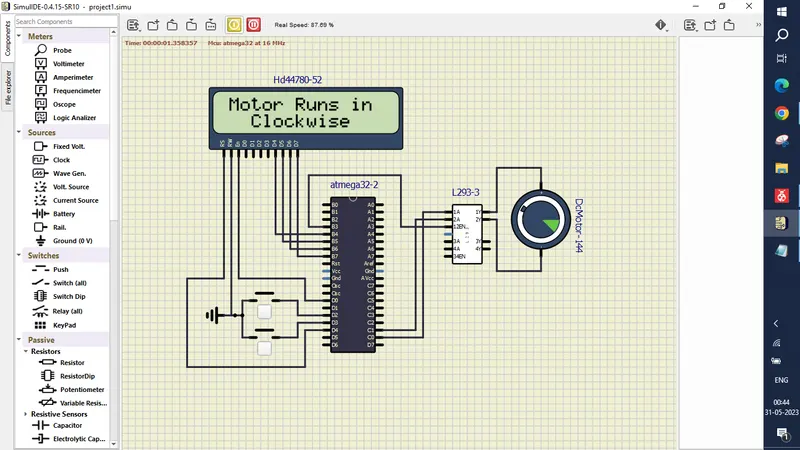
Here, in the clockwise rotation of the motor, if we want to increase the speed of the motor, we have to press the first push button (interrupt INT0 @ PIND2).
Now, if we want to run the dc motor in the anticlockwise direction, we need to press the second push button once (interrupt INT1 @ PIND3).
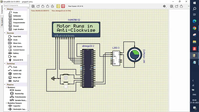
Now here also, in the anti-clockwise rotation of the motor, if we want to increase the speed, we have to press the first push button (interrupt INT0 @ PIND2).
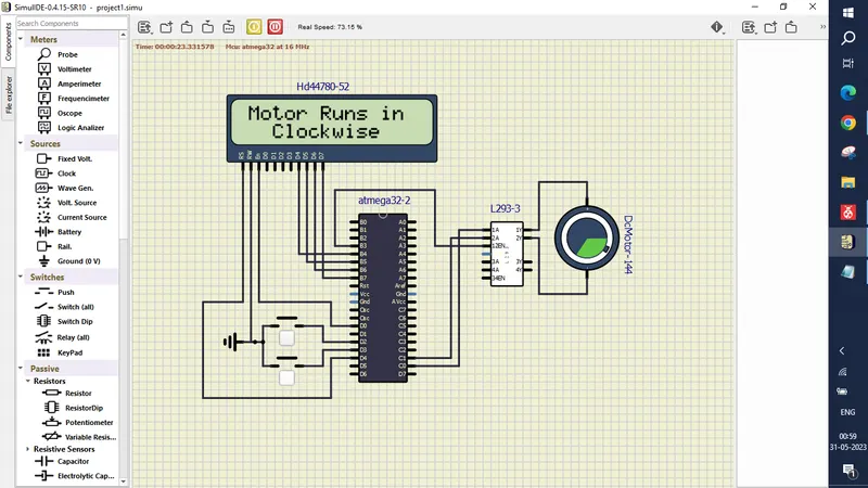
Again, if we want to change the direction of the motor, press the second push button.
OCR0 value is incremented each time by +10 when we press the first push button. OCRO values increment in the following way when we press the first push button: 64,74,84,94,104,114,124,134,144,154,164,174,184,194,204,214,224,234,244,254, (0 min -255 max count),8,18,28,38,48,58,68,78,88,98,108, ...
After reaching 254, now if we press the first push button one more time, the motors will now run at a very low speed. This is because OCR0 values now become 8 here, which will now get incremented each time with +10 when we press the first push button from its previous value.
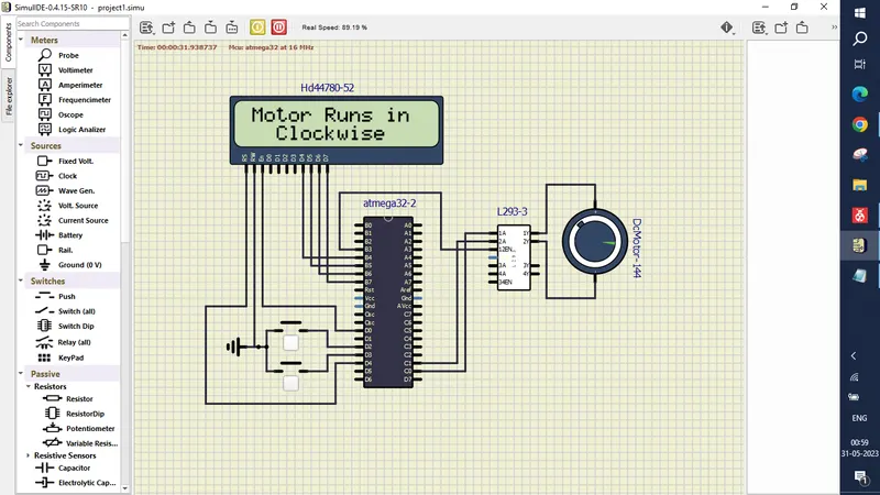
Result:
- Implemented the system on the simulator which controls the speed of the DC motor using PMW.
- The running status of the DC motor is monitored continuously using the L293 motor driver (which allows the DC motor to drive in any direction).
- Running status i.e. on which direction the DC motor is running is displayed on the LCD screen.