Project 1 - Controlling a DC motor using PWM and monitoring its Running status
Project 1 - Controlling a DC motor using PWM and monitoring its Running status
Overview of the Project:
Implement a system on the simulator for controlling a DC motor using L293 motor driver, monitor its status and print the running status of motor on the LCD Display.
Goals:
- Implement a system on simulator for Controlling the DC motor using L293 motor driver.
- Displaying the running status of DC motor on the LCD display.
Key Highlights of the Project:
- The DC motor can be controlled by using L293 motor driver.
- The speed of a DC motor can be controlled by varying its input voltage, for doing this is to use PWM (Pulse Width Modulation).
- L293D IC is a typical Motor Driver IC which allows the DC motor to drive on any direction.
AVR CODE:
#include <avr/io.h> // Including AVR Input/Output header file
#define F_CPU 16000000ul //define the CPU frequency
#include "avr/interrupt.h" // Including AVR interrupt header file
#include <util/delay.h> //Including Delay header file
#define sw_dir (PIND&(1<<1)) //d1 pin is declared as push button for direction control
#define sw_dspd (PIND&(1<<2)) //d2 pin is declared as push button for speed control
#define pw (PINC&(1<<3)) //c3 pin is declared as push button for power on/off.
#define lcd_port PORTB //portB pins are for LCD data
#define RS_high PORTD|=(1<<5) //d5 pin is used for resistor select pin of LCD (high)
#define RS_low PORTD&=~(1<<5)
#define EN_high PORTD|=(1<<6) //d6 pin is used for enable pin of LCD
#define EN_low PORTD&=~(1<<6)
unsigned char i; // Creating a global variable
void lcd_cmd(char cmd) // This function is to use LCD in command Mode
{
lcd_port=(cmd&0xf0); //Masking 4 bits for 4 bit LCD mode//
RS_low; // RS is low in command mode
EN_low; // setting EN bit low
_delay_ms(1); //small delay
EN_high; // again setting high to same EN bit
lcd_port=((cmd<<4)&(0xf0));
RS_low; // RS is low in command mode
EN_low; // making EN pin of LCD low
_delay_ms(1); // small delay
EN_high; // again setting HIGH to same bit
}
void lcd_data(char data) //This function is to use LCD is data mode
{
lcd_port=(data &0xf0); //masking 4 bits for bit LCD mode//
RS_high; //RS is high in data mode
EN_low; // setting EN bit low
_delay_ms(1); // small delay
EN_high; // again set high
// reapting
lcd_port=((data<<4)&(0xf0));
RS_high;
EN_low;
_delay_ms(1);
EN_high;
}
void lcd_init()
{
lcd_cmd(0x28);
_delay_ms(5); //used for 4 bits LCD mode //
lcd_cmd(0x02);
_delay_ms(5); //return the cursor to home//
lcd_cmd(0x01);
_delay_ms(5); //clear screen //
lcd_cmd(0x0C);
_delay_ms(5); //display ON cursor OFF//
lcd_cmd(0x06);
_delay_ms(5); //increment cursor//
lcd_cmd(0x80);
_delay_ms(5); //force cursor to begin 1st line //
}
void cursorpos(char x, char y)
{
if ((x<1||x>2)||(y>16)||(y<1)) //condition will check the rows 2 and 16 columns
{
x=1; //x=rows = 1
y=1; //y=columns = 1
}
if (x==1)
{
lcd_cmd(0x7F+y); //{80-1=0B}for starting the first list hex decimal value(80){y we are the 7F+y means we need to start from that column
}
else
{
lcd_cmd(0xBF+y); //{0C-1=0B} for starting the second line, 2nd row
}
}
void lcd_out(char x, char y, char *str) //here we are checking which position we want to print
{
cursorpos(x,y); // setting at our desire location
while (*str) // printing string till
{
lcd_data(*str);
str++; // printing word by word
}
}
int adc_read(char channel) // This function is to configure ACD
{
unsigned int a, result;
ADMUX=channel; //here we are going to use which channel we need to select in mux here using 2 bit
ADCSRA=0X80; // control and status register to enable the adc conversion enable the interrupt flag adc interrupt ADEN=1
ADCH=0x00; // showing the value 0 or clearing the adc register
ADCL=0x00; //showing the value 0
ADCSRA|=(1<<6); // to start the conversion 6 bit adsc high
while((ADCSRA&0x40)!=0); // when the conversion become zero means conversion of adc (0x40means interrupt pin)
a=ADCL; //dummy data type a and ais stored the adcl register (ADC0-ADC7)
result=ADCH; //store the high value (ADC8-ADC9)
result=result<<8; //to get proper result or aligned value we need to do left shift
result=result + a; //we are adding the ADCL+ADCH to get 16 bits
return result;
}
int main(void)
{
DDRB=0xFF; // declaring all 8 pins as output
DDRA|=((1<<0)|(1<<1)); // declaring A0 and A1 as output
DDRD&=~(1<<1); //declaring D1 pin as input
DDRD&=~(1<<2); //declaring D2 pin as input
DDRD|=(1<<5); //declaring D5 pin as output
DDRD|=(1<<6); //declaring D6 pin as output
DDRC&=~(1<<3); //declaring C3 pin as input
PORTD|=(1<<2); //enabling internal pull up resistor for D2
PORTC|=(1<<3); //enabling internal pull up resistor for D3
i=64; // initializing i=64 because we are running the motor with 25%duty cycle
TCCR0=0X61; // non inverting mode, PWM phase correct mode, no pre scalar
GICR=(1<<INT0); // using into for interrupt
MCUCR=0X02; // make interrupt negative edge triggered
sei(); //enabling interrupts
lcd_init(); // initialized LCD
while (1)
{
while(pw==0) //continue till push button is released
{
if (sw_dir==0) // if the direction control push button is released
{
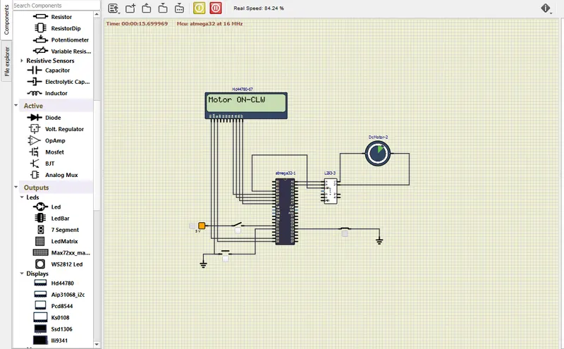
PORTA=0b00000001; //respective 1A 2A pins to rotate in clockwise direction
lcd_out(1,1,"Motor ON-CLW"); // running clockwise direction
}
else
{
PORTA=0b00000010; //respective 1A 2A pins to rotate in anti-clockwise direction
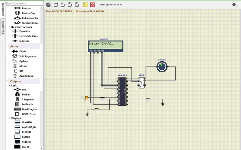
lcd_out(1,1,"Motor ON-ACL"); // running anti-clockwise direction
}
OCR0=i; // i increase in ISR, the corresponding value is to be loaded into OCR0
}
PORTA=0X00; //0 0 to respective 1A 2A pins to stop condition
lcd_out(1,1,"Motor is_OFF");
}
}
ISR(INT0_vect) // interrupts
{
i=i+20; //as i increases the duty cycle also increases .i increases by 20
//in each push and the corresponding value is to be loaded into
//OCR0 in while loop
}
COMPONENTS REQUIRED:
LCD DISPLAY- HD44780 LCD controller.
AVR - ATMEGA32
MOTOR- DC MOTOR
DRIVER- L293 DRIVER
PUSH BUTTON - 2 NO'S
SWITCH- 1 NO'S
GROUND - 2 NO'S
EXTERNAL POWER SUPPLY
CONNECTION DIAGRAM:
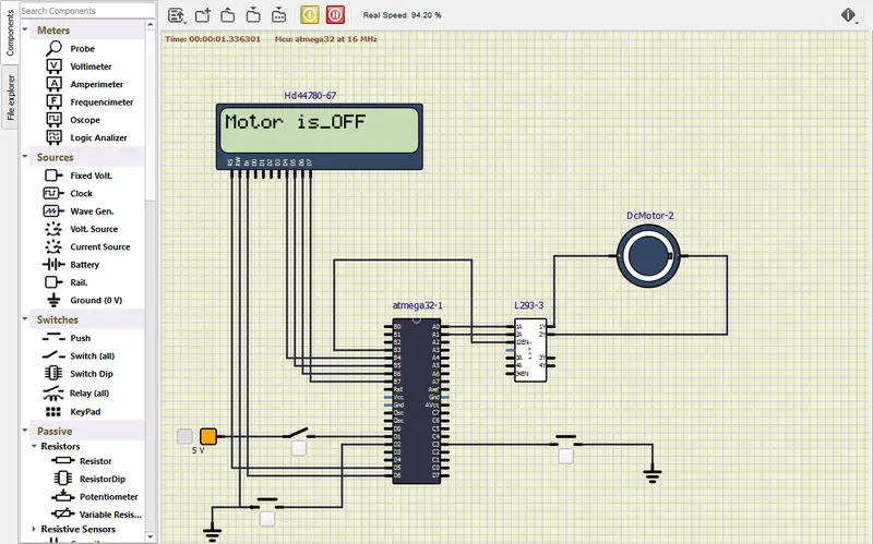
WORKING DIAGRAM:
MOTOR ON CLOCKWISE DIRECTION:
MOTOR ON ANTICLOCKWISE DIRECTION: