Project 1 - Controlling a DC motor using PWM and monitoring its Running status
Aim:
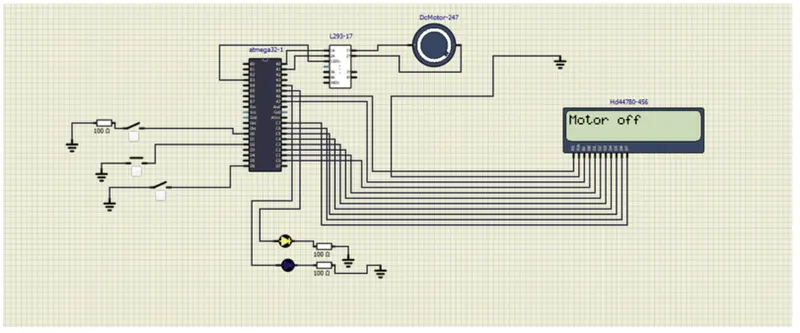
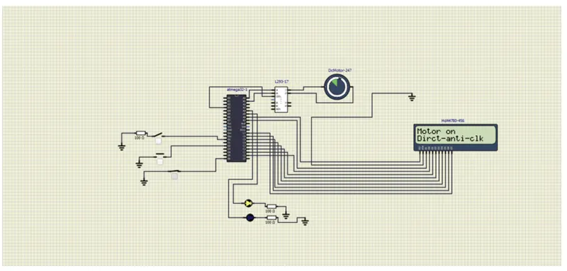
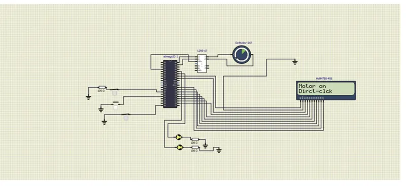
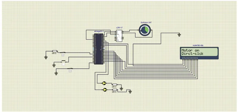
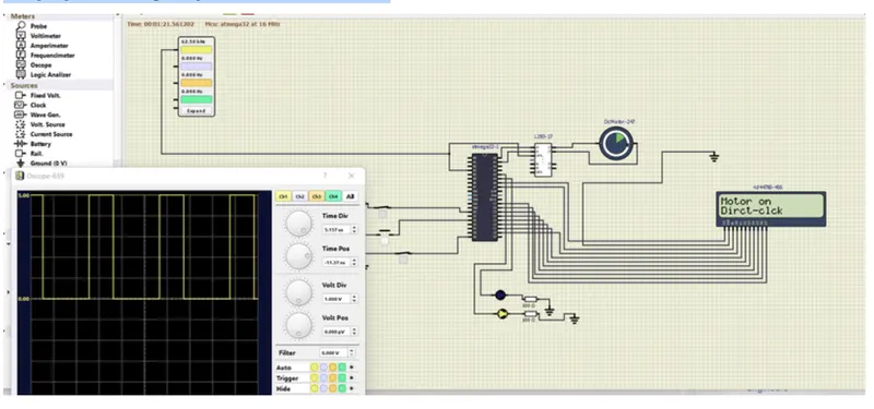
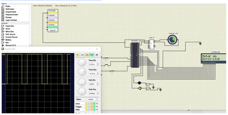
Implement a system on the simulator for controlling a DC motor using the L293 motor driver, monitor its status, and print the running status of the motor on the LCD Display.
code:
#define F_CPU 16000000L
#include
#include
#include
#define spcn PD2//declaring the d2 pin has speed control pin
#define dm PD0//declaring the d0 pin has speed control pin
#define mof PD6//declaring d6 as motor off switich
#define rs_high PORTA |=(1<<6)//enabling lcd register high
#define rs_low PORTA &=~(1<<6)//enabling lcd register low
#define en_high PORTA |=(1<<7)//enabling lcd enable high
#define en_low PORTA &=~(1<<7)//enabling lcd enable low
unsigned char i;
void lcd_cmd(unsigned char cmd)
{
PORTC = cmd;//giving cmd to the LCD
rs_low;//making register low
en_high;//making enable high
_delay_ms(1);
en_low;//making enable low
}
void lcd_data(unsigned char data)
{
PORTC = data;//giving data to the LCD
rs_high;//making register high
en_high;//making enable high
_delay_ms(1);
en_low;//making enable low
}
void lcd_init()
{
//Making lcd ready for displaying the output//
lcd_cmd(0x38);
_delay_ms(5);
lcd_cmd(0x02);
_delay_ms(5);
lcd_cmd(0x01);
_delay_ms(5);
lcd_cmd(0x0c);
_delay_ms(5);
lcd_cmd(0x06);
_delay_ms(5);
lcd_cmd(0x80);
_delay_ms(5);
}
void cursorpos(char x,char y)
{
if((x<1 || x>2)||(y<1 || y>16))//condtion check the 2 rows and 16 columns
{
x=1;
y=1;
}
if (x==1)
{
lcd_cmd(0x7F+y);//{80-1=7f} for starting the 1st line hex decimal value(80) y we r using means we need to dtart from that column
}
else
{
lcd_cmd(0xBF+y);//0c-1=0b for starting 2nd line,2nd row
}
}
void lcd_out(char a, char b,char *str)
{
cursorpos(a,b);//checking the cursor position or setting the position
while(*str)
{
lcd_data(*str);//sending the data to lcd function with string as argument
str++;
}
}
void motordir()
{
if((PIND &(1< { PORTA &=~(1<<1);//clearing the pin1 status before toggling PORTA|=(0b00000001);//00000001 PORTA|=(0x10);//for led blinking lcd_cmd(0x01);//clearing the lcd data lcd_out(1,1,"Motor on ");//printing the data motor on lcd_out(2,1,"Dirct-clck");//direction printing _delay_ms(500); } else{ PORTA &=~(1<<0);//clearing the pin0 status during the toggling PORTA|=(0b00000010);//00000010 PORTA|=(0x20); lcd_cmd(0x01); lcd_out(1,1,"Motor on "); lcd_out(2,1,"Dirct-anti-clk "); _delay_ms(500); } OCR0=i; } int main(void) { DDRA |=0xFF;//making all port has output DDRC |=0xFF;//making all port has output DDRD &=~(1< DDRD &=~(1< DDRD &=~(1< PORTD |=((1< DDRA |=((1<<0)|(1<<1));//making pin a0 and a1has output DDRB |=(1<<3);//making b3 has output PORTB |=(1<<3);//11making pin3 has high i=64; OCR0=i;//for 25 percent duty cycle TCCR0=0x61;//phase correct PWM GICR=(1< MCUCR=0x02;//neagtive edge trigger sei();//enable interrupt lcd_init(); while(1) { while((PIND &(1< { motordir();//while switich is closed then the we determine direction of the motor } PORTA=0x00;//turning off the motor condition PORTA|=(0x20); lcd_cmd(0x01); lcd_out(1,1,"Motor off");//calling the lcd function _delay_ms(500); } } ISR(INT0_vect)//enabling the int0 intruppt { i=i+20;//adding the value to the timer } Description: Here we want to carry out motor speed and direction control with Driver Ic L239.In Ic L239 when input is 01 then it rotates clockwise direction when input is IC 10 motor rotates in an anti clockwise direction. Motor speed is controlled by the Phase PWM method with interrupt enabling using sei() function and setting the OCR0 as 25 percent duty cycle with value 64. In the while loop, we check that pin d6 is close or open. If d6 is close it enters the direction motor function here we have the if condition it checks the pin d0 if d0 is closed it enters the loop in which port A0 A1 has 01 value, else A0A1 has 10 motors rotate anti-clockwise. Inside the motor direction function, we have LCD data function with the argument has row and column position and status has a motor on has string data. It prints the status of the motor on LCD. And in the interrupt, we have the condition of increasing the I value which means increasing the speed of the motor directly changes the OCR0 value. In this way, we control the speed of the motor. We are made D 0 6 1 pin are made pull up for the operation,IC enable pin is connected with B3 pin because OCR0 as output.PORTC made as output pin and it is connected with LCD. OUTPUT: When Motor Off the the power switch is an open condition: when Motor on by closing the power switch closing, the motor direction switch is the open means-AntiClockwise direction when Motor on by closing the power switch closing, motor direction switch is the close means-Clockwise direction By pressing the interrupt pin we can see the speed of the motor increase Here we can see the PWM wave with less width and see the motor runs slowly with the duty cycle being 50 percent in Pin Pin B3 Here we can see the PWM wave with more width and see the motor run faster with the duty cycle being 75 percent in Pin Pin B3