Week - 4
AIM : Implement control logic of a washing machine using stateflow.
OBJECTIVES :
- Understand and implement the logic control of a state matching stateflow.
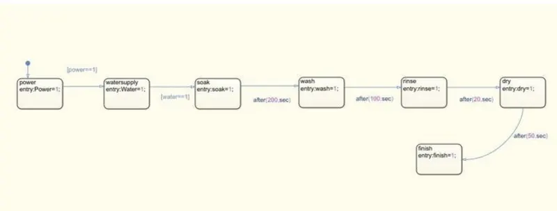
- If the power is available, the system gets activated.
- If the water supply is not available,stop the process &indicate through LED.
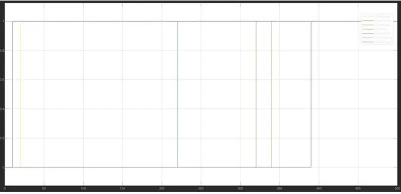
- Soaking time should be 200s followed by washing time of 100s.
- Then rinsing happens for next 20s & dryer runs for 50s.
**After all the processes have completed turn ON the finished LED**
BLOCKS USED :
Constant
scope
chart
lamps
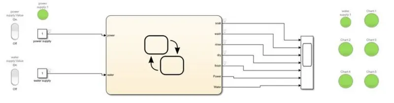
SIMULINK MODEL :
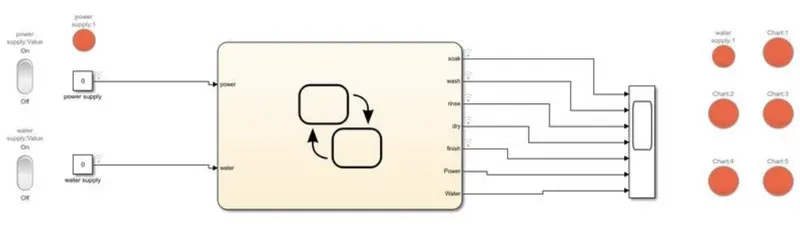
CASE 1 : With power and water OFF condition is shown below.
In this condition power supply, water supply, soak, wash, rinsh and dry are under OFF condition which is shown in red colour LED.
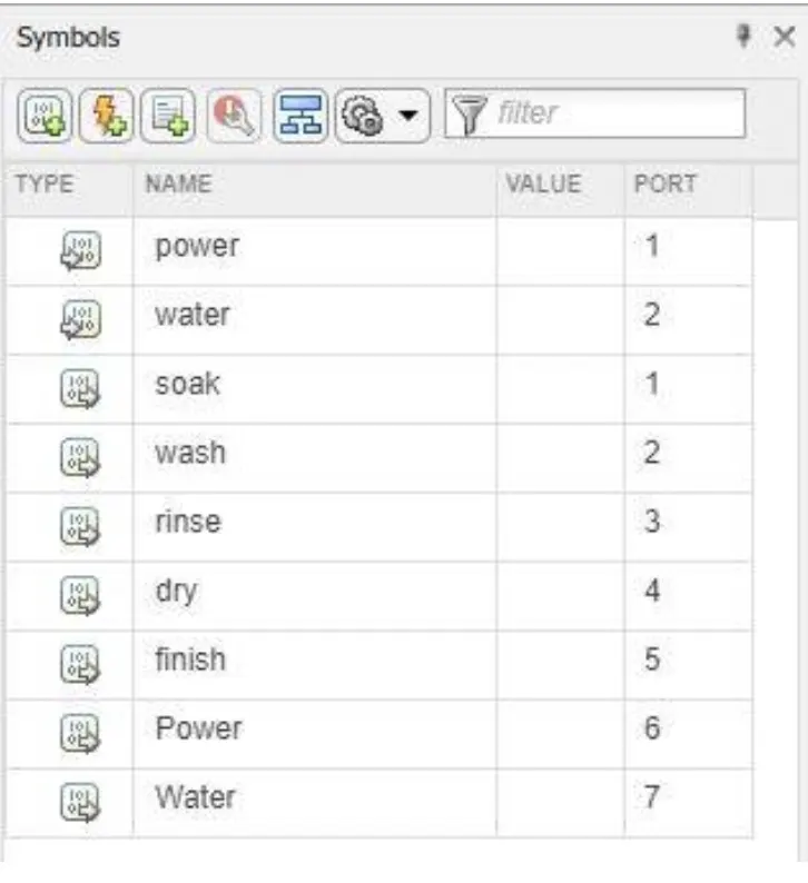
BLOCKS INSIDE THE CHART WITH PORT DETAILS :
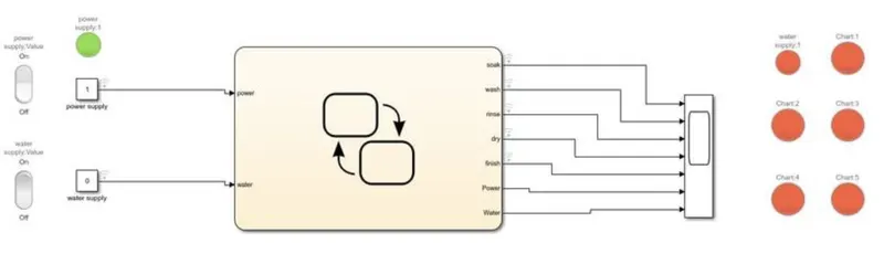
CASE 2 : When power supply is turned ON and water supply is turned OFF.
Under this condition the power supply will only show Green colour LED and remaining process will show Red colour LED because without water supply the wasing machine can't operate.
CASE 3 : When both power and water supply are turned ON.
Under this condition the washing time 100sec and rinsing happens for next 20sec & dryer runs for 50sec. After completion of entire process the green LED all process will be shown including finish LED green.
OUTPUT GRAPH :
CONCLUSION :
- The logical control of the state machine could be executed as per required.
- The real time changes in the simulation could also be observed if the simulation time is set to infinity.
- More features could be added like different modes of washing.
GEAR SHIFT LOGIC : A gear shift mechanisam for a manual transmission includes a shaft axially movable for selecting shift planes and rotatable for engaging the gears defining the shift plane . The shaft is held in a reference shift plane by two helical springs.
AIM : Make a simulink chart for gear shift logic .
OBJECTIVES : Make a simulink chart for gear shift logic as
speed range (kmph) Gear
0 to 15 1
16 to 25 2
26 to 40 3
41 to 60 4
Above 61 5
Give speed input while the simulation is running & display the gear number.
SIMULINK BLOCKS :
- Constant
- Slider gain
- Chart
- Display
- Scope
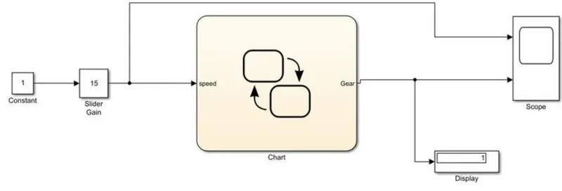
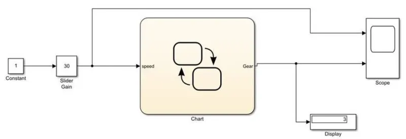
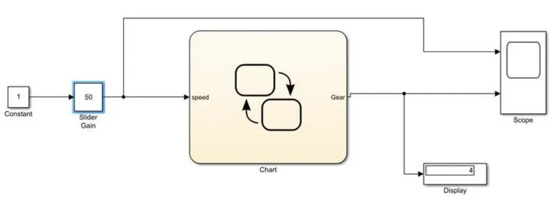
SIMULINK DIAGRAM :
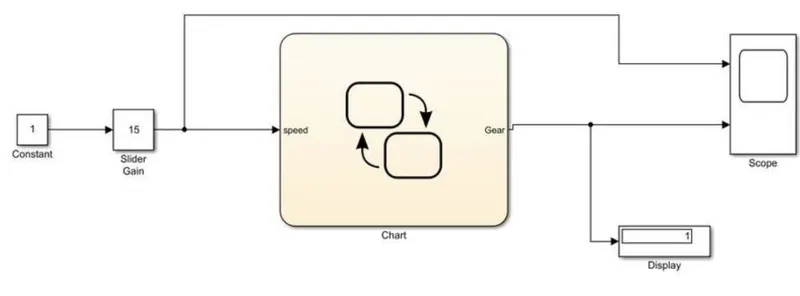
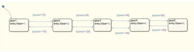
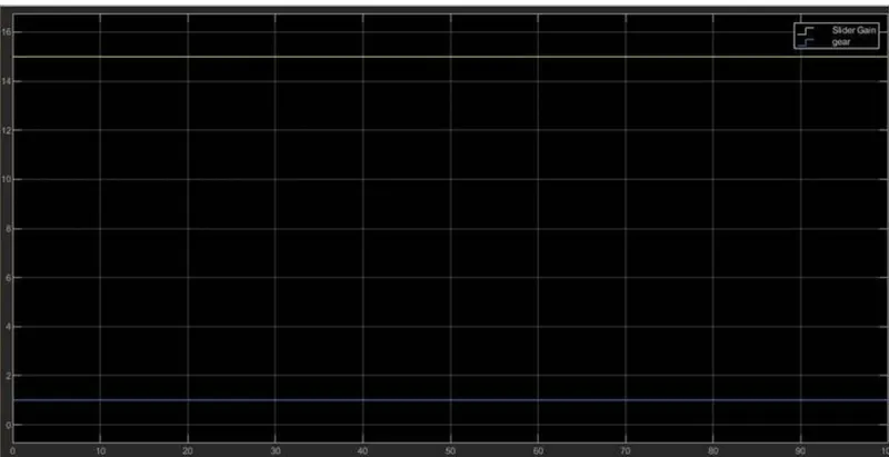
CASE 1 : If the speed is 15km/hr, then the gear shift is in 1st position.
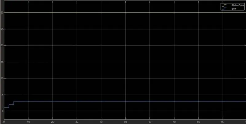
GRAPH :
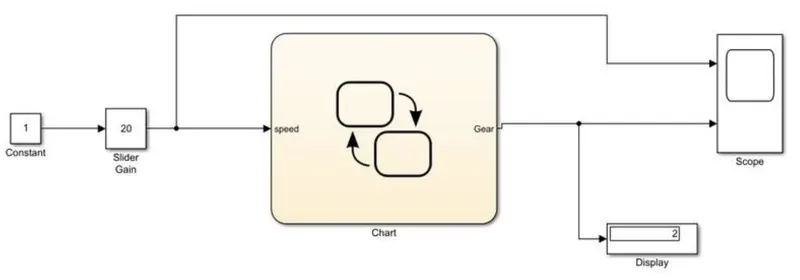
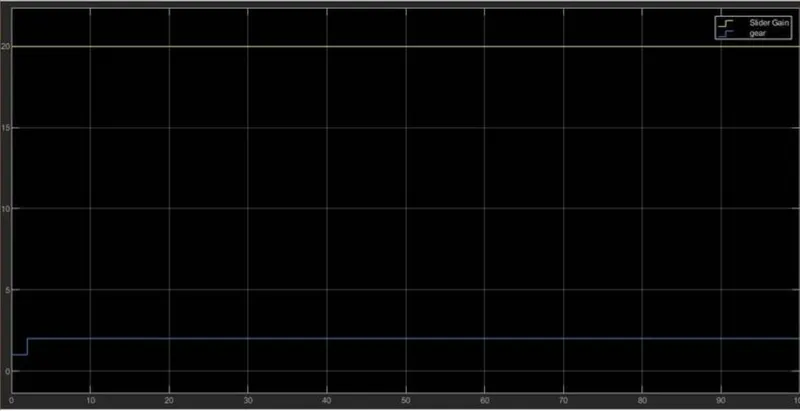
CASE 2 : If the speed is 20km/hr, the gear shift is in 2nd position
GRAPH :
CASE 3 : If the speed is 30km/hr, the gear shift is in 3rd position.
GRAPH :
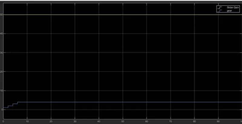
CASE 4 : If the speed is 50km/hr, then the gear shift in 4th position.
GRAPH :
CONCLUSION : A simulink model is created for the gear shift logic and using slider gain the values are obtained.