Project
AIM :
To carry out a system level simulation of an All-Terrain vehicle(ATV).
OBJECTIVES :
- To carry out a simulation of ATV.
- To preapare a technical report explaining the model properties &comments on the result.
THEORY :
ALL -TERRAIN VEHICLE (ATV)
An All-terrain vehicle (ATV), is also known as a light utility vehicle (LUV), a quad bike, or simply a quad. It is a vehicle that travels on low- pressure tyres and has a seat that is straddled by the operator along with handlebars for steering control. It is mainly built for a broader of terrain.
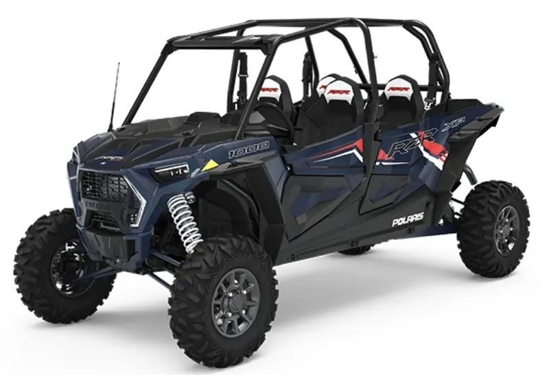
COMPONENTS OF ATV :
Here is the list of components used in ATV.
- Vehicle body
- Suspension
- Tire
- Engine
- Continuously variable transmission (CVT)
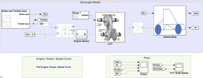
SIMULINK MODEL :
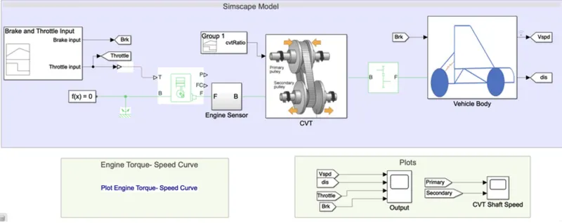
BLOCKS USED :
Here is the list of blocks used in this model :
- Siganl builder
- GO TO
- Simulink - PS converter
- Generic engine
- Solver configuration
- Mechanical rotational reference
- Engine sensor
- Simple gear
- Chart
- From
- Scope
SIGNAL BUILDER :
The signal builder block allows you to create inter changeable groups of piece model. It can quickly switch the signal groups into and out of a model to facilitate testing.
In this model there are two inputs named break and Throttle input.
GENERIC BREAK :
Represents a system- level model of spark ignition and diesel engines suitable for use at the initial stages of modelling when only the basic parameters are available. Optional idle speed and red line controllers are included.
The Throttle input signal T lies between zero and one and specifies the torque demanded from the engine as a fraction of the maximum possible torque. If the engine speed falls below the stall speed, the engine torque is blended to zero. If the engine speed exceeds the maximum speed, the simulation stops and issues an error message.
Connections F and B are mechanical rotational conserving ports associated with the engine crankshaft and engine block, respectively. Connections P and FC are physical signal outputs ports through which engine power and fuel consumption rate are reported.
ENGINE SENSOR :
The sensor is connected with a Generic engine . It consists of
- Ideal mechanical rotational sensor block measure angular velocity or angle in a mechanical rotational network. The sensor is ideal since it does not account for inertia, friction, delays, energy consumption &so on.
- PS Terminator block is used to terminate physical signal outputs. Unconnected physical signal output ports do not generate warnings, but a connection to a PS Terminator can be used to indicate that the signal was not in advertently left connected.
- The sensor is further connected with a CVT sub system.
CVT SUB SYSTEM :
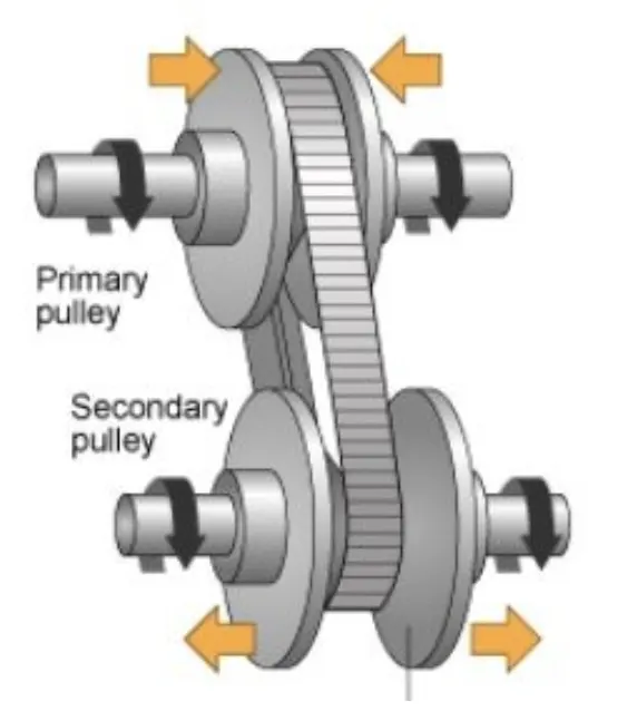
The CVT mainly consists of
- Primary pulley
- variator
- secondary pulley
- belt
CONDITIONS :
- If the primary pulley moves inward while thee secondary pulley moves outward then it will lead to overdrive.(Rp>Ra).
- If the primary pulley moves outward and the secondary pulley moves inward then it will lead to speed reduction (Rp<Ra).
This CVT subsystem consist of various blocks such as Input&output shaft inertia, variable Gear transmission, Ideal rotational motion sensor and PS Terminator along with mechanical rotational reference.
SIMPLE GEAR :
Represents a fixed - ratio gear or gear box. No inertia or compliance is modelled in this block.It includes gear meshing, backlash, and viscous bearing losses. Connections B(base) is connected to the CVT subsystem while connection F(follower) is connected to the vehicle body. The connections are mechanical rotational conserving parts that specify the relation between base and follower rotation directions with the output shaft rotates parameter.
VEHICLE BODY :
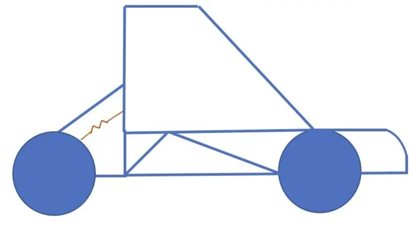
Represents a two- axle vehicle body in longitudinal motion. The block accounts for body mass , aerodynamic drag, road incline, and weight distribution between axles due to acceleration and road profile. The vehicle can have the same or a different number of wheels on each axle.
STUDY 1 : ALL-TERRAIN VEHICLE(AVT) WITH CVT
SIMULINK MODEL
SIGNAL BUILDER :
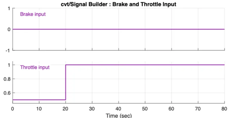
- Brake input is constant i.e zero throughout the given sample timewhich is 80seconds.
- Throttle input is 0.5 for 20seconds, later it increases to 1 for the remaining time till 80seconds.
ENGINE TORQUE-SPEED CURVE :
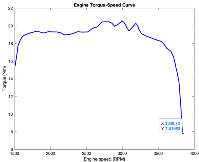
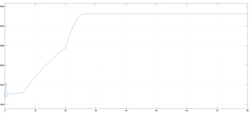
Vehicle speed depends on CVT ratio. The data is extracted using the GRABIT command which is available in the work space. From the above graph, we have got the maximum velocity which is 3839.72 Rpm.
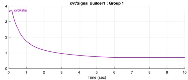
CVT RATIO:
RESULTS :
ENGINE SPEED :
VEHICLE SPEED :
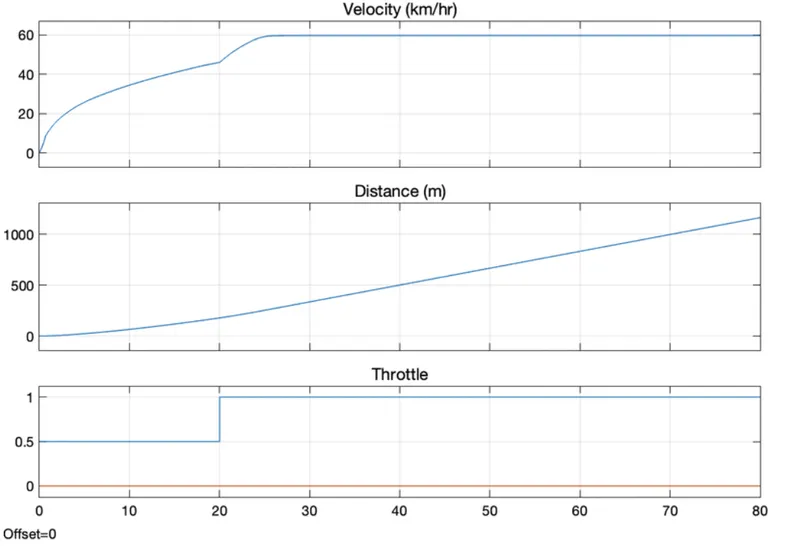
While providing Throttle input, we observed if the value 0.3 is consideredthen the velocity shows a sudden drop in the speed hence we changed it to 0.5 to get the smooth flow of velocity.
CVT SHAFT SPEED :
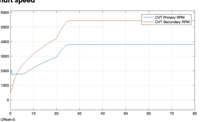
The CVT shows variations with respect to primary and secondary RMP based on their ratio.
STUDY 2 : ALL-TERRAIN VEHICLE (AVT) WITH CVT AND DASHBOARD
SIMULINK MODEL :
EXPLANATION :
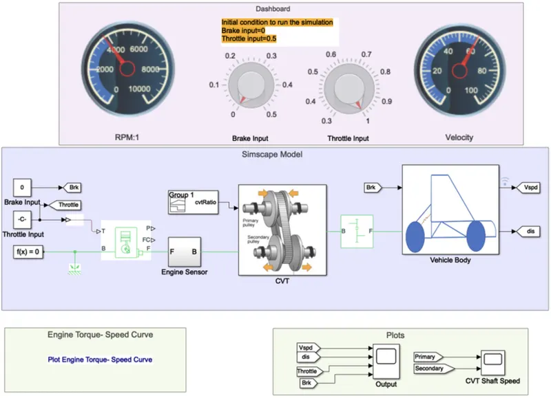
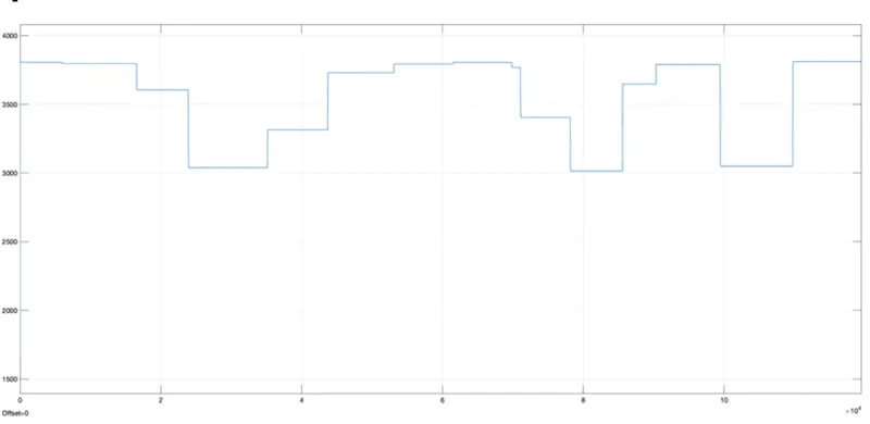
- This model is similar to that of the previous one, the one extra that is added over here is dashboard which as brake and throttle input knobs that allows the user to change the input values while the simulation is running.
- We kept the brake input as zero where as the throttle keeps on changing based on the input by the user.
- The change in throttle inputs results in the changes in the vehicle speed which varies simultaneously with it.
RESULTS :
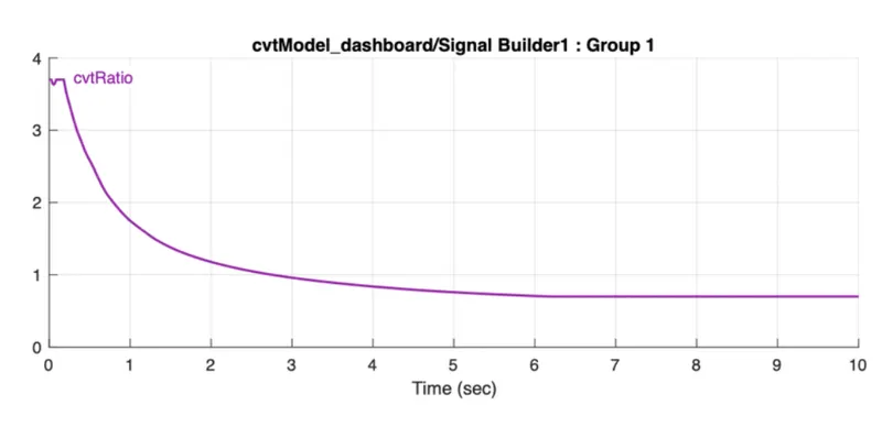
CVT :
ENGINE SPEED :
VEHICLE SPEED :
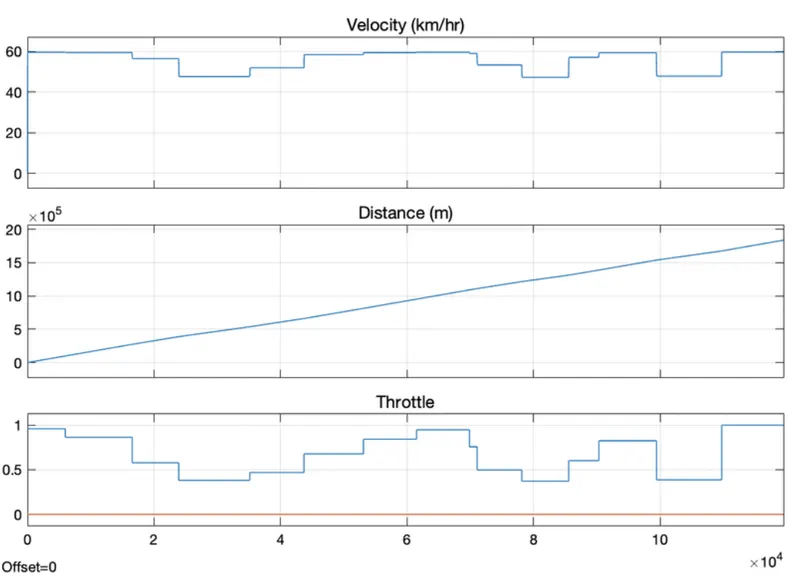
In this, brake input is 0 and the throttle input is variable with the help of the knob. The change in the throttle input reflects in the velocity as well.
CVT SHAFT SPEED :
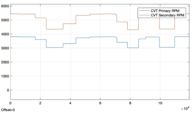
The CVT shows variations with respect to primary and secondary Rmp based on their gear ratio.
STUDY 3:
ALL-TERRAIN VEHICLE(AVT) WITH CVT USING LOOK UP TABLE :
SIMULINK MODEL :
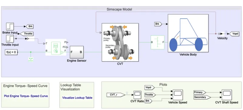
EXPLANATION :
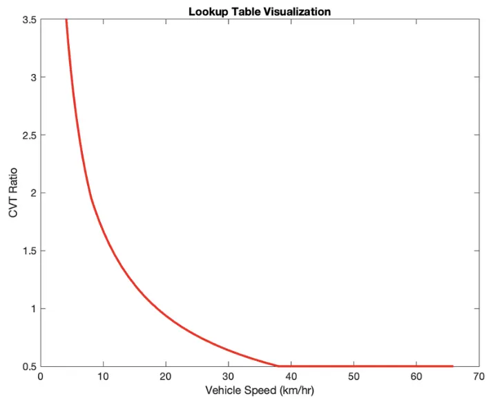
- In this model, the brake and throttle use a step signal as an input. Hving a look up table with CVT ratio Vs vehicle speed as a visualization table helps to specify the CVT ratio.
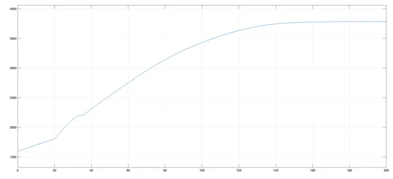
- Then model runs for 200sec and gave us the output in the form of various plots.
- They are engine speed, vehicle speed and CVT shaft speed.
RESULTS :
LOOK UP TABLE :
CVT RATIO :
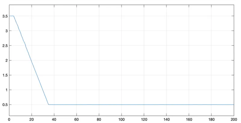
The look up plot and the CVT ratio plot is similar.
ENGINE SPEED :
VEHICLE SPEED :
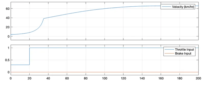
In this , brake input is 0 and the throttle input is 0.3 for 20 sec later 1 for rest. The velocity of the vehicle shows gradual growth for the first 20sec later on it increases from 20-40 sec till the speed gets stable.
CVT SHAFT SPEED :
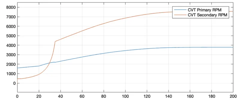
The CVT shows variations with respect to primary and secondary RMP based on their gear ratio.
STUDY 4 : ALL-TERRAIN VEHICLE (AVT) WITH CVT AND DASHBOARD USING LOOK UP TABLE
SIMULINK MODEL :
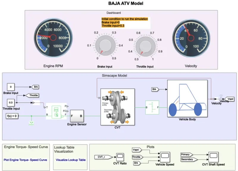
EXPLANATION :
- This model is similar to the previous model. The only difference is dashboard along with a lookup table.
- Here the inputs can be given using the knobs on the dashboard. One is for brake and the other is for Throttle inputs.The simultaneous changes will show us the impact on vehicle speed.
- Here brake input =0 and the throttle input can be increased or decreased during the simulation.
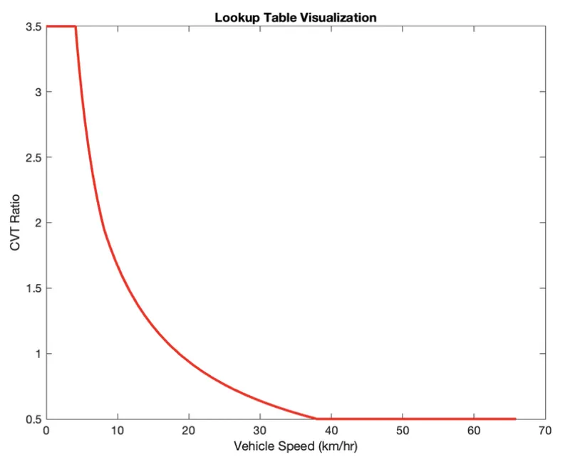
- The look up table values need to be arranged in ascending and descending order to work.
- We simulated for an period and gave Throttle input to get the final results.
RESULTS :
LOOKUP TABLE VISUALIZATION :
ENGINE SPEED :
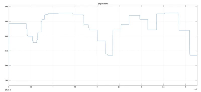
VEHICLE SPEED :
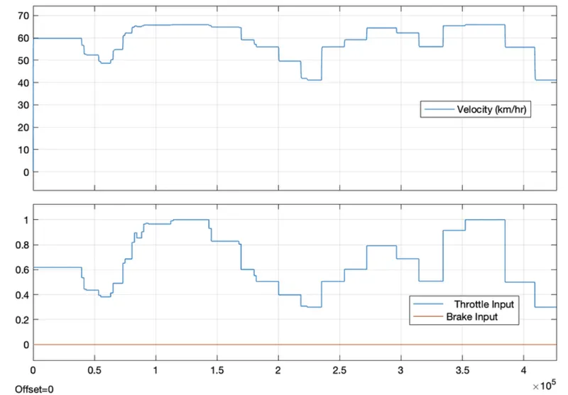
From the graph, once the throttle is increased the speed is increased and viceversa for the decrease in the throttle input. The brake remains zero throughout the simulation. The vehicle shows similar changes with reference to the throttle input.
CVT SHAFT SPEED :
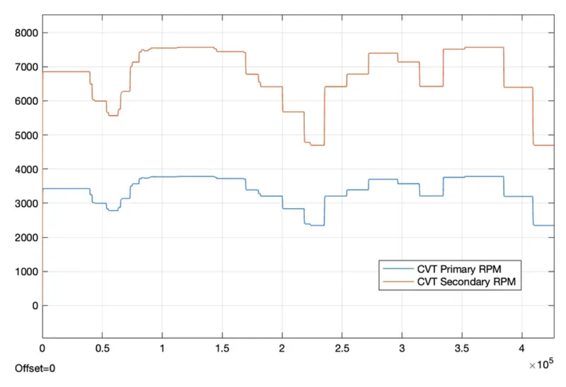
The CVT shows variations with respect to primary and secondary RMP based on their gear ratio.
CONCLUSION :
We ran a system- level simulation for a BAJA All-Terrain vehicle (AVT) model using CVT with or without Dashboard and lookup table based on the above obtained results in the form of Engine speed, Vehicle speed, and CVT shaft speed helped to determine the vehicle's performance.
REFERENCES :
- The BAJA All-Terrain vehicle (AVT) model
- Git Hub file.