Project 1 - Controlling a DC motor using PWM and monitoring its Running status
QUESTION:
Project 1 - Controlling a DC motor using PWM and monitoring its Running status
SOLUTION:
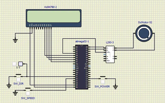
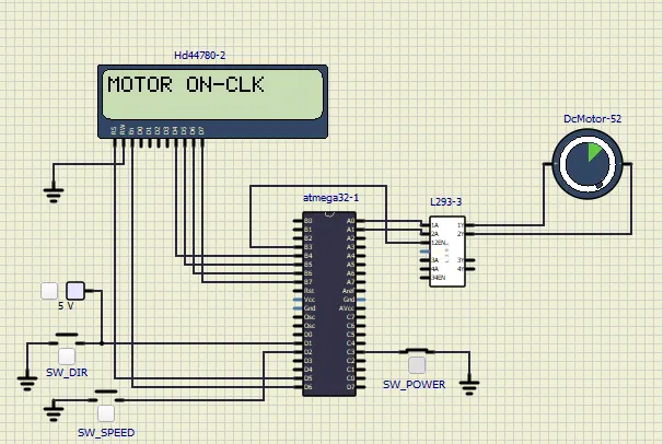
---> CIRCUIT:
---> CODE:
/*
* Project1.c
*
* Created: 27-12-2022 16:52:25
* Author : ZEBA KHANUN
*/


#include <avr/io.h> //includes appropriate I/O definitions for the device
#define F_CPU 16000000L //tells compiler the CPU frequency to use for various delays
#include <util/delay.h> //Function where actual time values rather than a number of cycles to wait for
#include <avr/interrupt.h> //provides a set of default interrupt routines

#define LCD_PORT PORTB //defines which PORT of ATmega will be used to interface LCD

//RS bit tells whether we are going to send an Instruction or a piece of data
#define RS_HIGH() PORTD |= (1<<5) //for data
#define RS_LOW() PORTD &= ~(1<<5) //for instruction

//EN bit enables writing to the registers if HIGH
#define EN_HIGH() PORTD |= (1<<6)
#define EN_LOW() PORTD &= ~(1<<6)

//Switches to provide inputs to the operation of motor
#define SW_DIR (PIND & (1<<1)) //to control the direction of the motor
#define SW_SPEED (PIND & (1<<2)) //to control the speed of the motor
#define SW_POWER (PINC & (1<<3))  //to control the power of the motor

unsigned int i = 0; //global variable declaration

void LCD_COMMAND (unsigned char cmd) //commands to run when the LCD RS bit is LOW
{
	LCD_PORT = (cmd & (0xF0));
	RS_LOW();
	EN_LOW();
	_delay_ms(1);
	EN_HIGH();
	LCD_PORT = ((cmd<<4) & (0xF0));
	RS_LOW();
	EN_LOW();
	_delay_ms(1);
	EN_HIGH();
}

void LCD_DATA (unsigned char data) //Commands to process the data of LCD RS bit is HIGH
{
	LCD_PORT = (data & (0xF0));
	RS_HIGH();
	EN_LOW();
	_delay_ms(1);
	EN_HIGH();
	LCD_PORT = ((data<<4) & (0xF0));
	RS_HIGH();
	EN_LOW();
	_delay_ms(1);
	EN_HIGH();
}

void LCD_INIT() //Commands to initialize the LCD display
{
	LCD_COMMAND(0x28);
	_delay_ms(5);
	LCD_COMMAND(0x02);
	_delay_ms(5);
	LCD_COMMAND(0x01);
	_delay_ms(5);
	LCD_COMMAND(0x0C);
	_delay_ms(5);
	LCD_COMMAND(0x06);
	_delay_ms(5);
	LCD_COMMAND(0x80);
	_delay_ms(5);
}

void CURSOR_POS(char x, char y) //function to set LCD Display cursor
{
	if((x<1)|(x>2)||(y<1)|(y>16))
	{
		x = 1;
		y = 1;
	}

	if(x == 1)
	{
		LCD_COMMAND(0x7F+y); //to start from 1st line
	}
	else
	{
		LCD_COMMAND(0xBF+y); //to start from 2nd line
	}
}

void LCD_OUT(char x, char y, char* str) //to display the passed string on lcd
{
	CURSOR_POS(x, y);
	while(*str)
	{
		LCD_DATA(*str);
		str++;
	}
}

int ADC_READ (char channel) //ADC data processing we are configuring the ADC value
{
	unsigned int a, result;
	ADMUX = channel; //ADC Multiplexer selection bit helps to enable particular ADC channel
	ADCSRA = 0x80; //ADC Status and control register - ADEN is HIGH
	ADCH = 0x00; //clearing the ADCH register to store the higher byte of converted data
	ADCL = 0x00; //clearing the ADCL register to store the lower byte of converted data
	ADCSRA |= (1<<6); //ADSC bit is high to start conversion
	while((ADCSRA & (0x40)) != 0); //performing bitwise AND operation between ADCSRA and ADIF (INTERRUPT FLAG bit 4th bit in ADCSRA)
	a = ADCL; //storing lower byte of converted data in local variable a
	result = ADCH; //storing higher byte of converted data in local variable result
	result = result << 8; //as the ADLAR is 0 data is right justified so performing left shift
	result = result | a; //bitwise OR operation to store higher and lower byte of converted data in variable result
	return result;	//returning result value
}

int main(void)
{
	DDRB = 0xFF; //setting PORTB as output port
	DDRA |= ((1<<0)|(1<<1)); //Setting PORTA pin 0, 1 as output
	DDRD &= ~(1<<1); //setting PORTD pin1 as input
	DDRD &= ~(1<<2); //setting PORTD pin2 as input
	DDRB |= (1<<5);  //setting PORTB pin5 as output
	DDRB |= (1<<6);  //setting PORTB pin6 as output
	DDRC &= ~(1<<3); //setting PORTC pin3 as input
	PORTD |= (1<<2); //enabling internal pull-up resistor
	PORTC |= (1<<3); //enabling internal pull-up resistor
	i = 64; //storing value of OCR0 in global variable i
	TCCR0 = 0x61; //timer control register 0 configured for PWM phase correct mode, no prescaling
	GICR = (1<<INT0); //general interrupt control register
	MCUCR = 0x02; //MCU control register - ISC01 is high(falling edge of INT0 generates interrupt request)
	sei(); //enabling interrupt
	LCD_INIT(); //initializing LCD
	while(1)
	{
		while(SW_POWER == 0)
		{
			if(SW_DIR == 0)
			{
				PORTA = 0b00000001;
				LCD_OUT(1,1,"MOTOR ON-CLK");
			}
			else
			{
				PORTA =0b00000010;
				LCD_OUT(1,1,"MOTOR ON-ACL");
			}
			OCR0 = i;
		}
		PORTA = 0x00;
		LCD_OUT(1,1,"MOTOR IS OFF");
	}
}

ISR (INT0_vect)
{
	i = i+20; //incrementing OCR0 value by a step size of 20 every time interrupt is called
}
---> EXPLANATION:
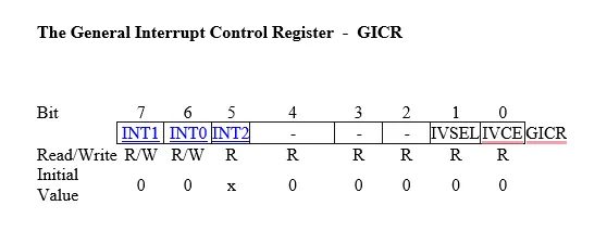
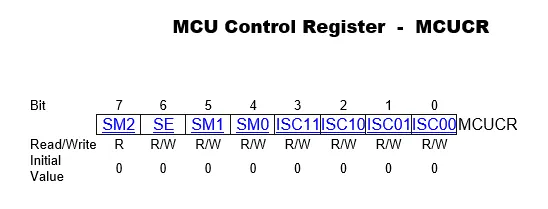
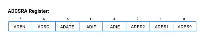
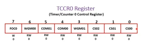
Above mentioned are special function registers used for timer0, ADC, and interrupts. We have configured the bits of these special function registers for the functionality.
GICR - INT0 bit (to enable INT0)
MCUCR - ISC01 (falling edge of INT0 will generate interrupt request)
ADCSRA - ADEN, ADIF (to enable ADC conversion, enable ADC interrupt flag)
TCCR0 - WGM00, COM01, CS00 (No prescaling, PWM phase correct mode)
---> SCREENSHOTS:
CLOCKWISE DIRECTION:
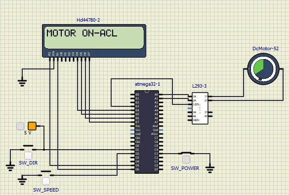
ANTICLOCKWISE DIRECTION: