Project 1_Comparative study of different storey buildings for Seismic forces
AIM:
Factors influencing the dynamic characteristics of a building
Factors influencing the Natural Period of a building
Factors influencing the Mode shape of oscillations
INTRODUCTION:
Factors influencing the dynamic characteristics of a building
In many practical circumstances, the vibration characteristics of a dynamic structure
require to be understood and, subsequently, an accurate mathematical model needs to be
derived. Such a model is needed for response and load prediction, stability analysis,
system design, structural coupling etc.
Since a dynamic structure is a continuous system rather than a discrete one, theoretically,
an infinite number of coordinates are necessary to specify the position of every point on
the structure and hence the structure can be said to have an infinite number of degrees of
freedom. Its vibration characteristics should then include an infinite number of vibration
modes and cover the active frequency range from zero to infinity. However, for most
practical applications, only a certain frequency range is of major interest and only those
vibration characteristics which fall in this range will be investigated. In this case, only a
certain number of vibration modes are to be sought and it becomes feasible to represent
the continuous system by an approximate, discrete, one.
For a discrete linear dynamic system with lumped masses and massless elastic
components, theory has been well developed to study such vibration characteristics. This
is because the differential equations of a discrete linear dynamic system are generally
available, and hence mathematics can be introduced directly to solve the equations of
motion and the vibration characteristics can then be defined accurately. For a truly
continuous system, such as a practical structure, such advantages do not exist. However,
like many other sciences to achieve good approximation by discretization, the strategy of
investigating the vibration characteristics of a practical structure relies basically on the
hypothesis of discretizing the structure so that the theory for discrete systems can then
apply and the mathematical model for the structure can then be built. It is evident that as
the number of coordinates employed in the discretization approaches infinity, the discrete
system will approach the continuous one.
Basically, there are two ways of achieving a mathematical model for a dynamic structure
with the help of the discretization concept, they being by theoretical prediction and by
experimental measurement respectively. Both approaches effectively assume that the
vibration characteristics of a continuous system within certain frequency range can be
described approximately by a limited number of coordinates. In the following, both
approaches are reviewed briefly.
Factors influencing the Natural Period of a building
As the height of building increases, its mass increases but its overall stiffness decreases. Hence, the natural period of a building increases with increase in height. Buildings A, B, F and H have same plan size, but are of different heights.
Factors influencing the Mode shape of oscillations
1. Effect of Flexural Stiffness of Structural Elements
The overall lateral translational mode shapes depend on the flexural stiffness of beams relative to that of adjoining columns. The fundamental mode shape of buildings changes from flexural-type to shear-type as beam flexural stiffness increases relative to that of column.
2. Effect of Axial Stiffness of Vertical Members
Mode shapes depend on axial stiffness of vertical members in a building (i.e., of columns or structural walls).
Small Axial Stiffness causes significant axial compressive and tensile deformation in columns in addition to single or double curvature flexural deformations.
Additional Axial Deformation changes the fundamental mode shape from shear-type to flexural type, particularly in tall buildings.
Pure Flexural Response is not desirable because of large lateral sway, particularly at higher floors. Hence, designers ensure that the axial areas are large of building columns and structural walls.
3. Effect of Degree of Fixity at Member Ends
Highly Flexible soils make column bases as good as hinged, and rocky layers below as good as fixed.
Lack of Rotational Fixity at the Column Base (hinged condition) increases the lateral sway in the lower storey than in the higher storey, and the overall response of the building is more of shear-type.
On the other hand, full rotational fixity at the column base restricts the lateral sway at the first storey and thus, induces initial flexural behaviour near the base.
The overall response of the building is still of shear-type due to flexural stiffness of beams.
4. Effect of Building Height
In well-designed Low Height moment frame buildings, the fundamental translational mode of oscillation is of shear-type.
Buildings become laterally flexible as their height increases. As a result, the natural period of buildings increases with an increase in height. However, the fundamental mode shape does not change significantly (from shear type to flexure type).
Flexural type behaviour is exhibited only near the lower storeys where the axial deformation in the columns could be significant, particularly in tall buildings. However, at higher floor levels, the response changes to shear type as the axial load level lowers.
5. Effect of Unreinforced Masonry Infill Walls in RC Frames
URM Infill Walls are not considered in Analysis and Design of RC Frame Buildings in current design practice in many countries.
They are assumed to not carry any vertical or lateral forces, and hence, declared as non-structural elements insofar as the transfer of forces is concerned between structural elements (e.g., beams and columns) that are generated in the building during earthquake shaking.
PROCEDURE:
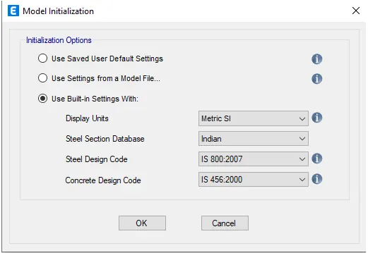
Open ETABS software choose a new model file ,a dialogue box will open choose use built-in settings with & codes & give ok.
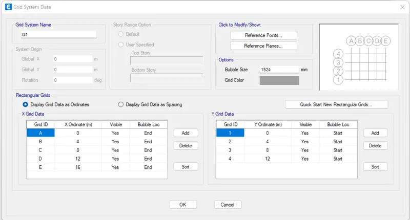
Now model quick templates will open choose the grids ,add one more grid & give the value for x & y coordinate & give ok.
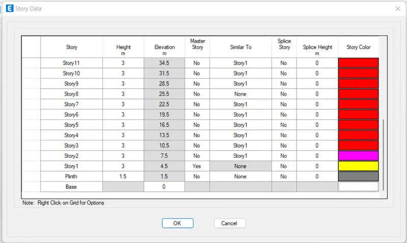
Edit story data & give ok
Now edit the stories plinth height at 1.5m+25 storey height 3m.storey 1 as labelled as master storey & all the above levels are similar to that.
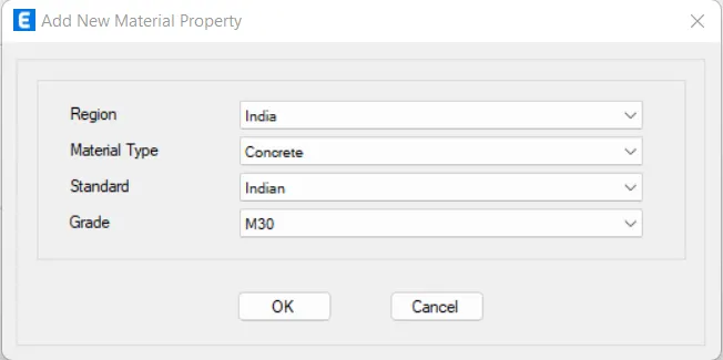
Under define tab,choose material ,material type concrete & give ok.
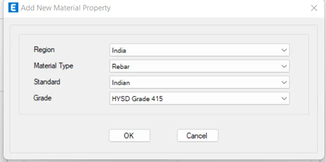
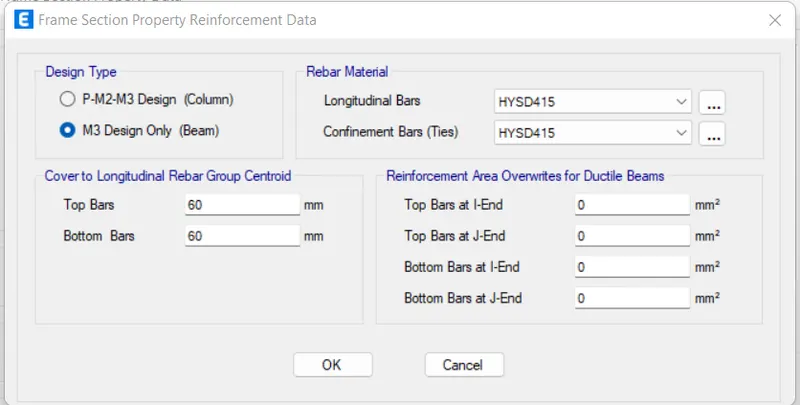
Provide the reinforcement as HYSD grade 415 & give ok
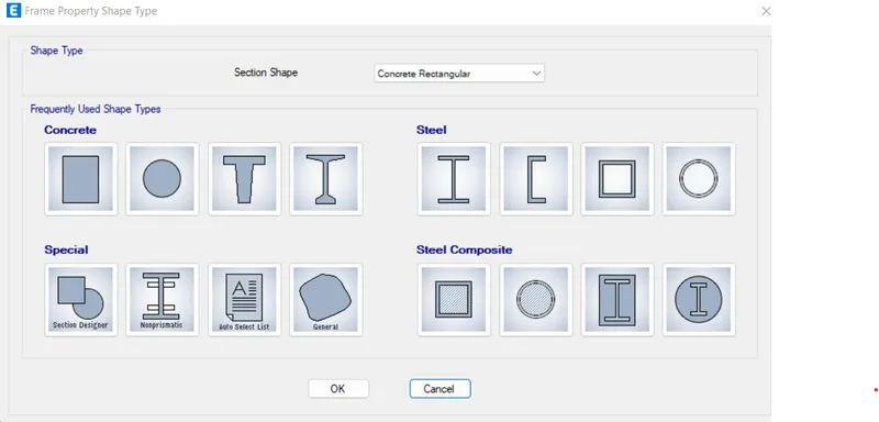
Go to define tab >section properties>frame properties
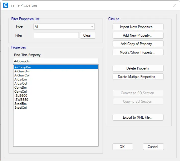 Add new property,provide beam size 300*400
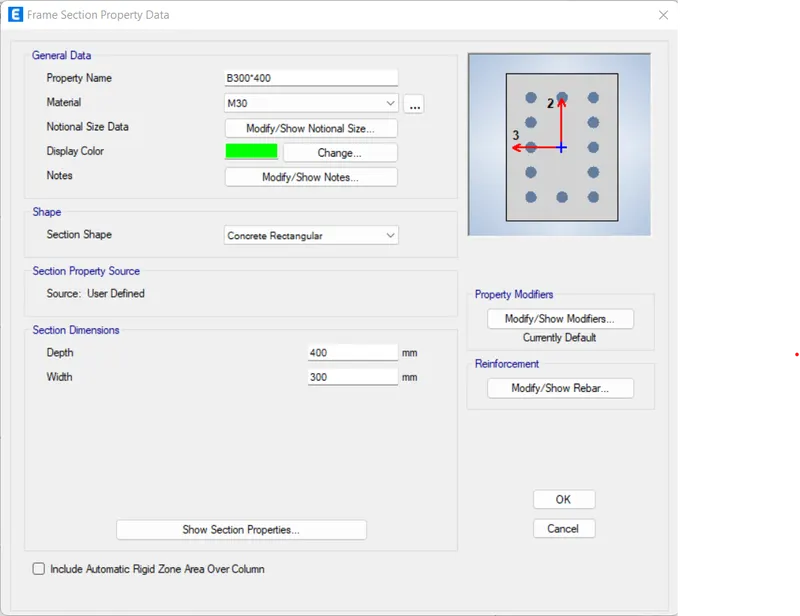
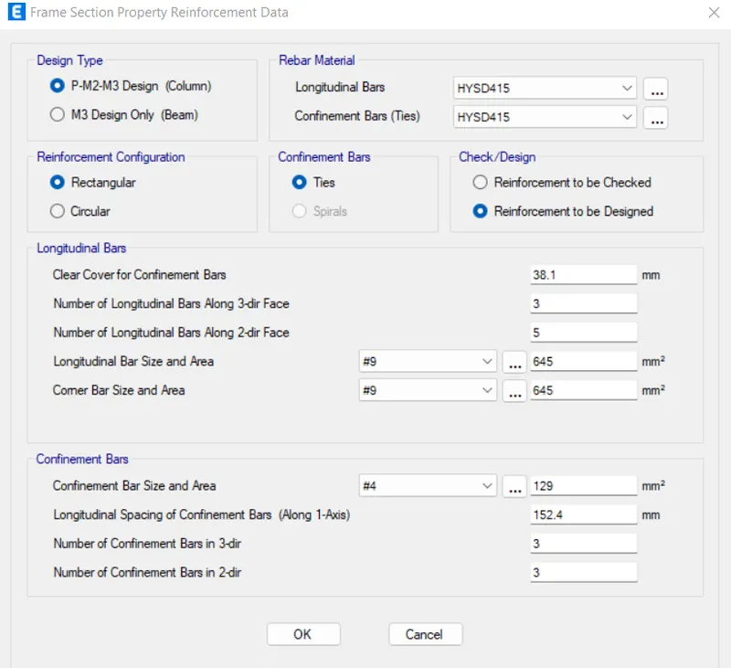
Modify reinforcement
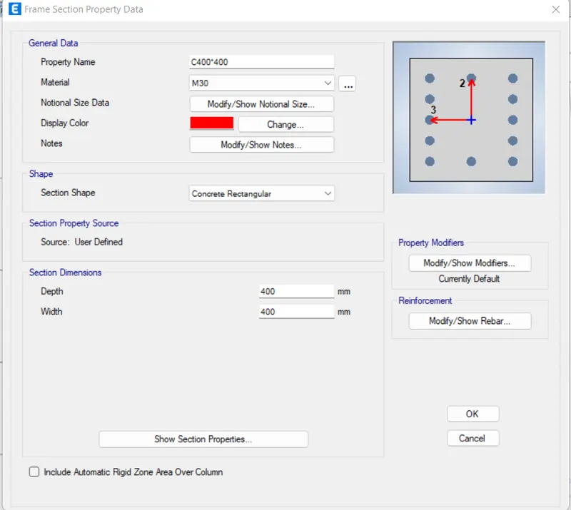
Provide column data of size 400*400
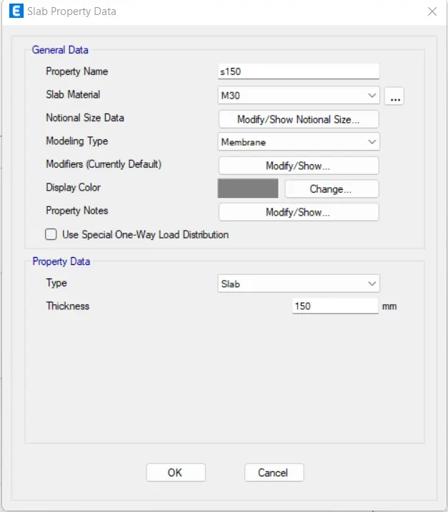
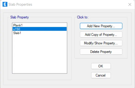
Go to slab property under define tab & provide slab data
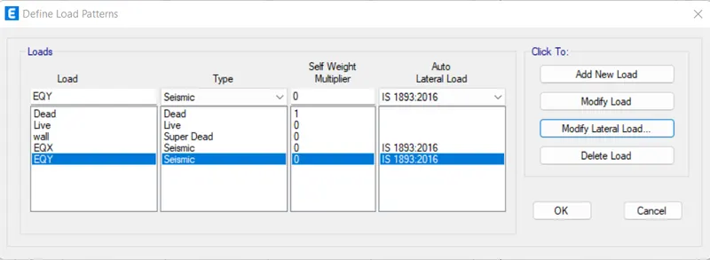
Define the load pattern
Define the mass source

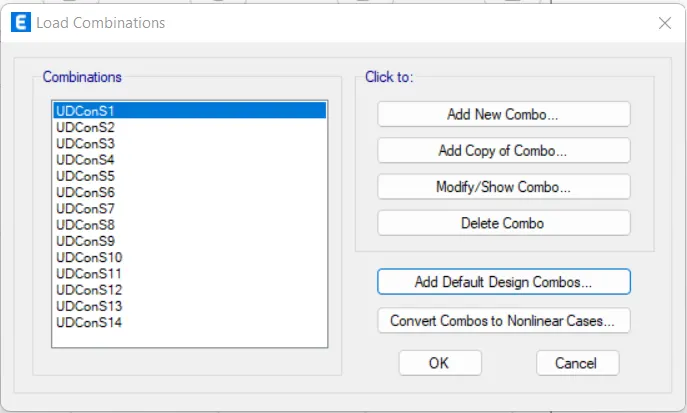
Provide load cases & load combinations for concrete frame design
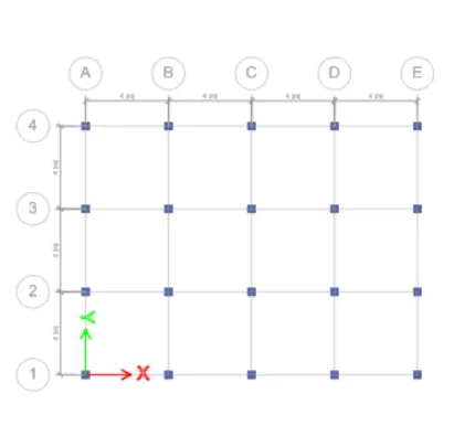
 Create the column
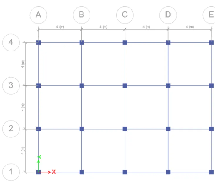
Now to create a beam ,choose beam >beam property>all storey >select the grids to create a beam
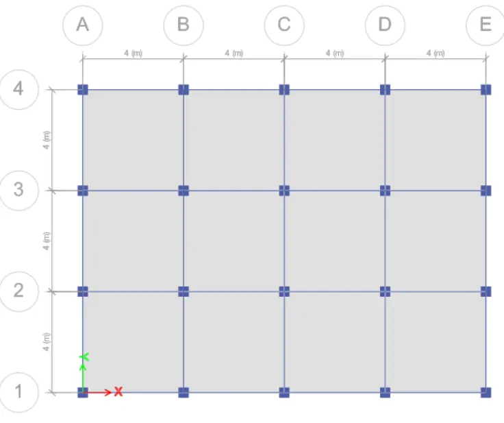
Go to quick draw slab ,choose the property s150 & create the slab
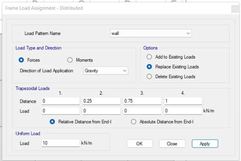
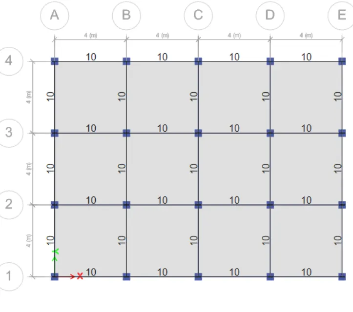
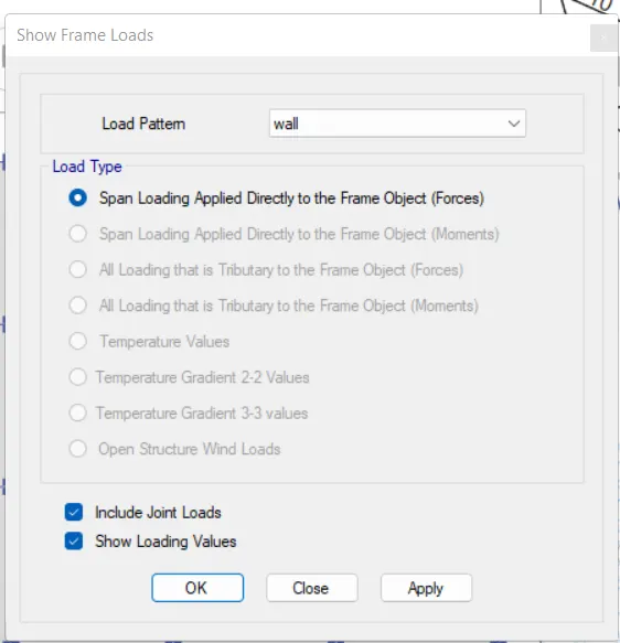
Now to assign the load choose the beam property ,now all the beams are selected ,choose the wall & provide a load of 10KN/m
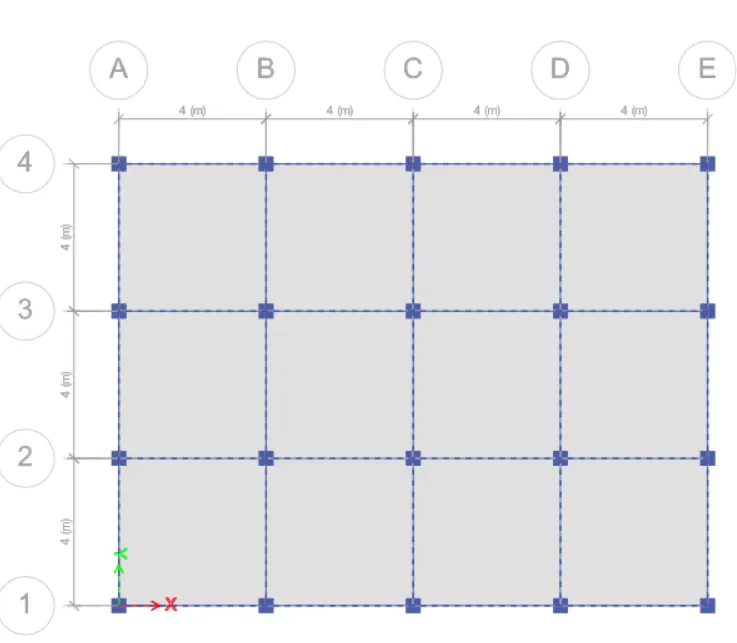
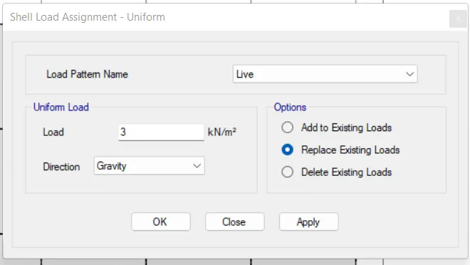
Assign the load of 3kN/m^2 to the slab
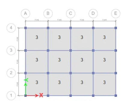
Set diaphragm & run analysis & save the file as G+25 model A
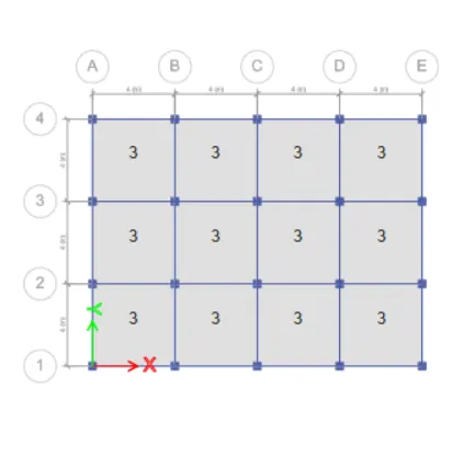
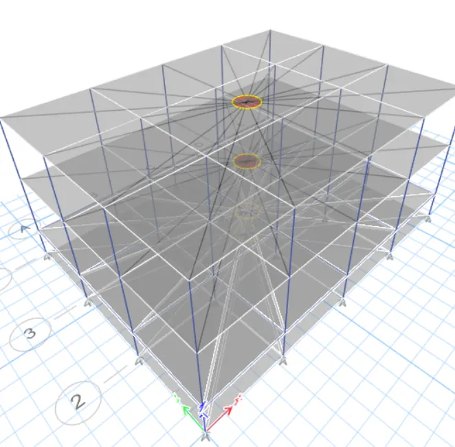
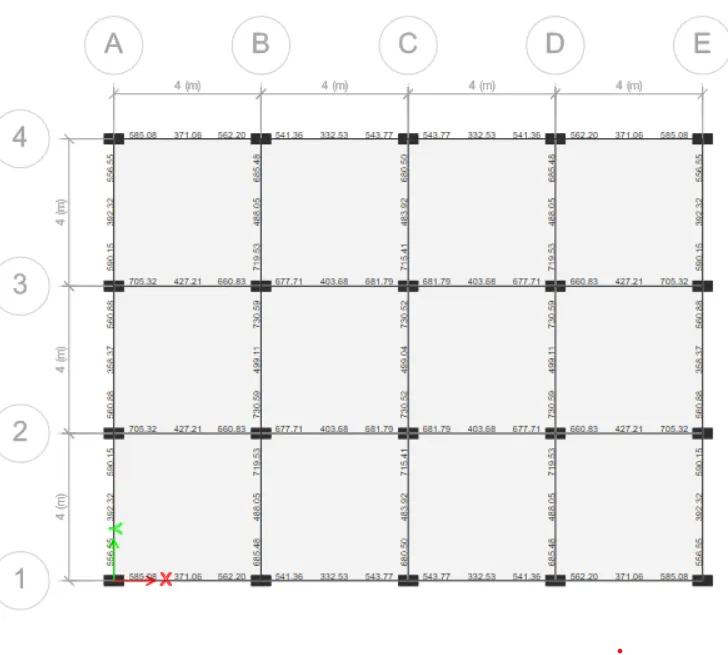
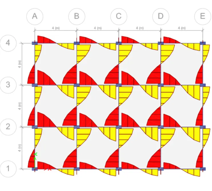
Run analysis the model is analyzed & deflection pattern ,BMD & SFD are cross checked logically.Model provide reliable results
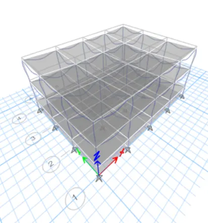
Now the created model has been saved as G+25 model A
Now open a new file & save it as G+25 model B
Go to edit tab>edit storeys & grids >Add story>Refresh the view to see the changes>ok
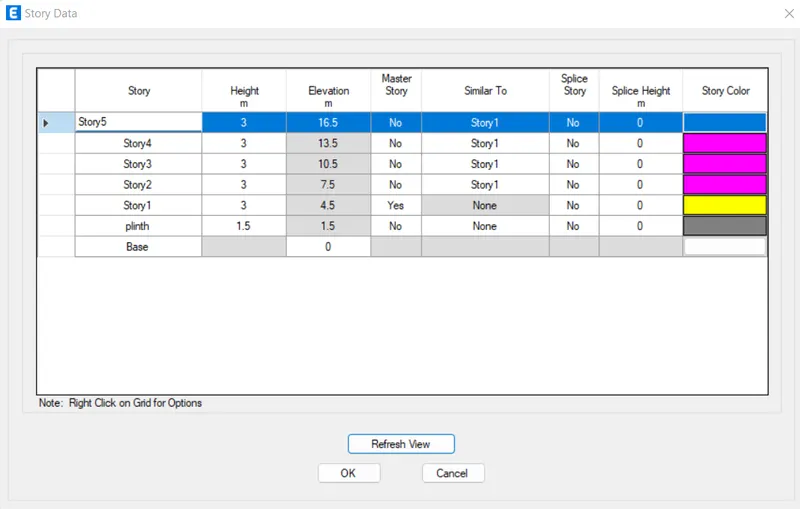
Cross check the load cases are visible or not
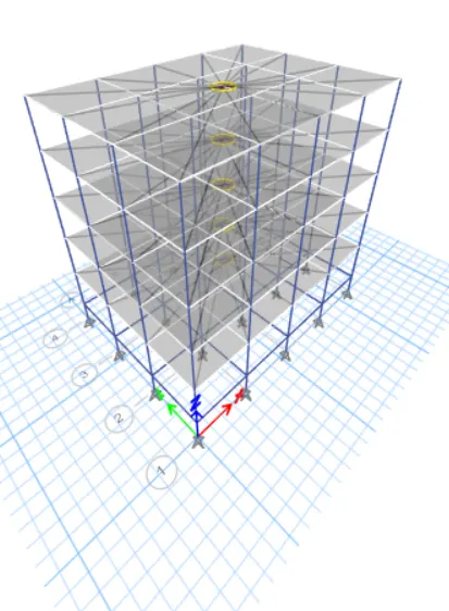
Insure the slab & assign the diaphragm.
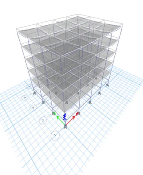
Run anlaysis now the deformed shape as been shown
Open a new file & save it as G+25 model c
Now provide a column of size 550*300
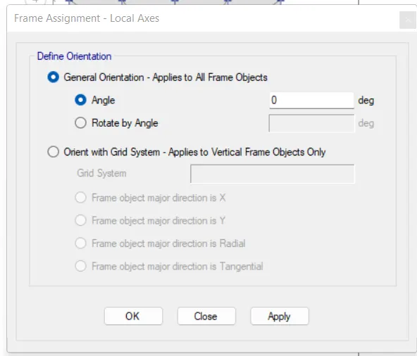
Assign local axis as 90 deg
Assign diaphragm & run analysis now the deformed shape is visible
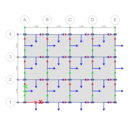
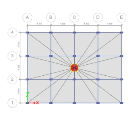
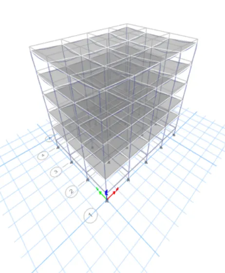
Open a new file & save it as G+25 model D
Now provide a column of size 550*300
Assign local axis as 0 deg
Assign diaphragm & run analysis now the deformed shape is visible
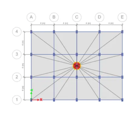
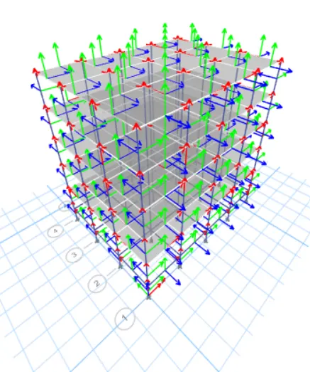
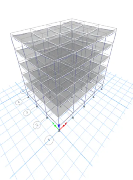
Now open a new file & save it as G+25 model E
Go to edit tab>edit storeys & grids >Add story>Refresh the view to see the changes>ok
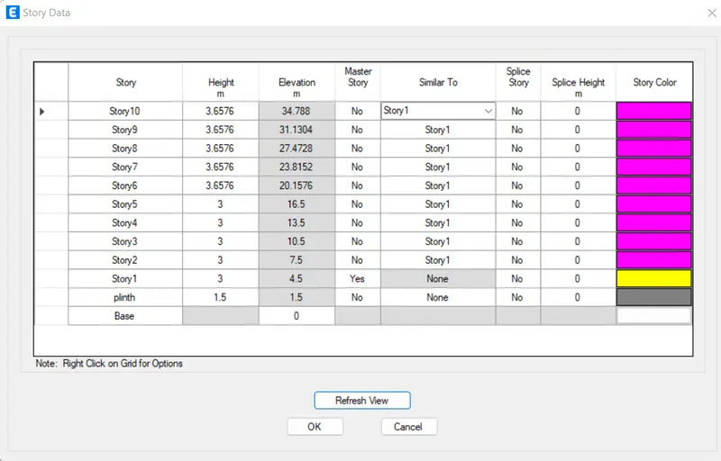
Go to define tab >section properties>frame properties
Providing column of size 600*600
Unhide beams & floors & apply
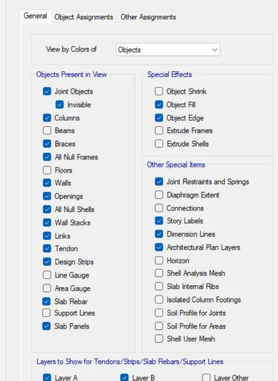
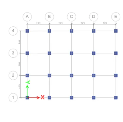
Go to 3d view, set building view limits
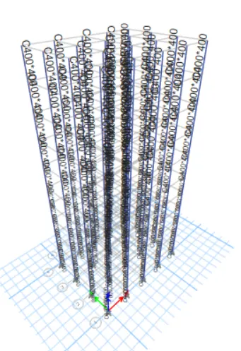
Assign diaphragm & run analysis now the deformed shape is visible
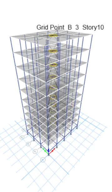
Add storey & refresh view
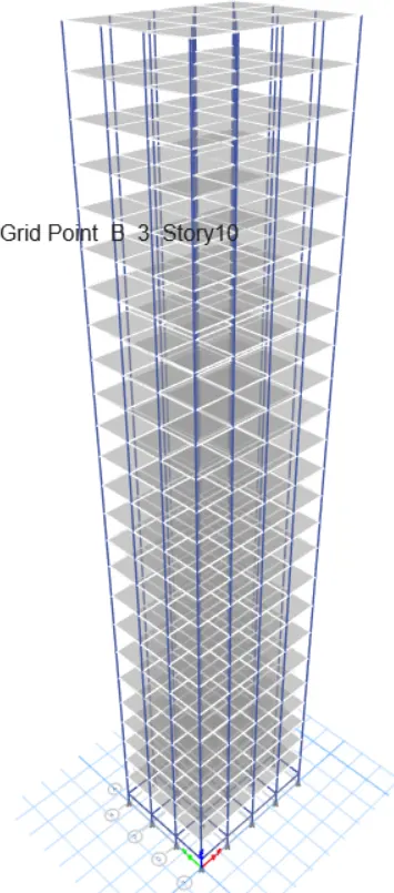
Define column of size 800*800
Follow the same procedure followed for model E
Set diaphragm & run analysis
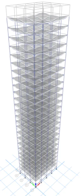
Create a new file G+25 Model H
Follow the same process followed in model G
Run analysis
Assign shell loads 3.3 & run analysis
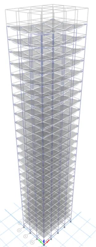
Create a another file of G+5 model k
Assign shell load of 3.6
Run analysis
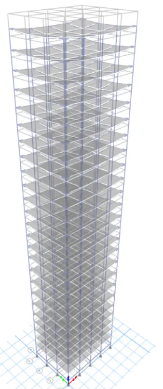
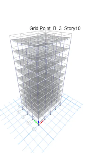
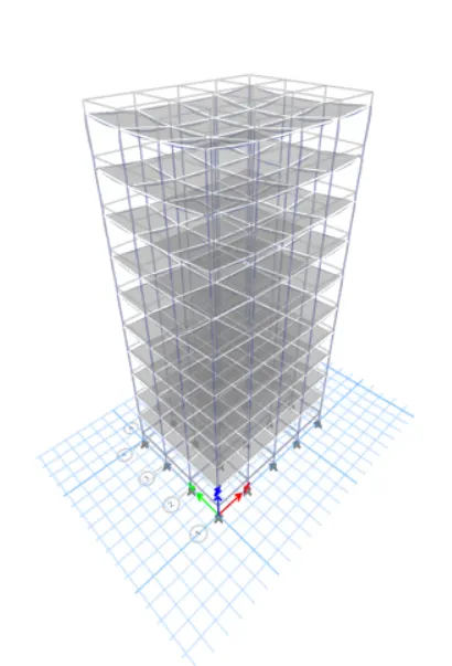
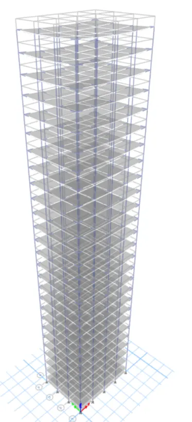
RESULT:
Open model E file
Click on Display>show tables>Analysis results>Structure ouput>Modal information>modal periods and frequencies.
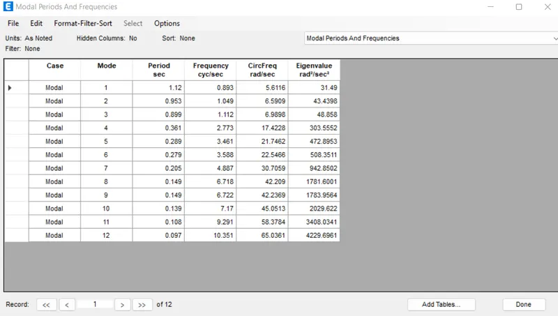
Column distribution loads:
Building E (10 storey with various column size load)=1.12s
Building F (10 storey with various column size load)=1.86s
Building G (25 storey with various column size load)=1.84s
Building H (25 storey with various column size load)=4.57s
Building H (25 storey with 3kM/sq.m imposed load)= 4.57s
Building j (25 storey with 3.3kM/sq.m imposed load)=4.75s
Building k (25 storey with 3.6kM/sq.m imposed load)= 4.76s
Effect of building height on time period:
Building A (2 Storey)= 0.5s
Building B (5 Storey)= 1.08s
Building F (10 Storey)=1.86s
Building H (25 Storey)=4.57s
Effect of column orientation on time period:
Building B (All floor column size 400*400)= 1.08s
Building C (All floor column size 550*300)oriented in x direction= 1.03s
Building D (All floor column size 300*550)oriented in y direction= 1.14s
Lateral Reinforcement
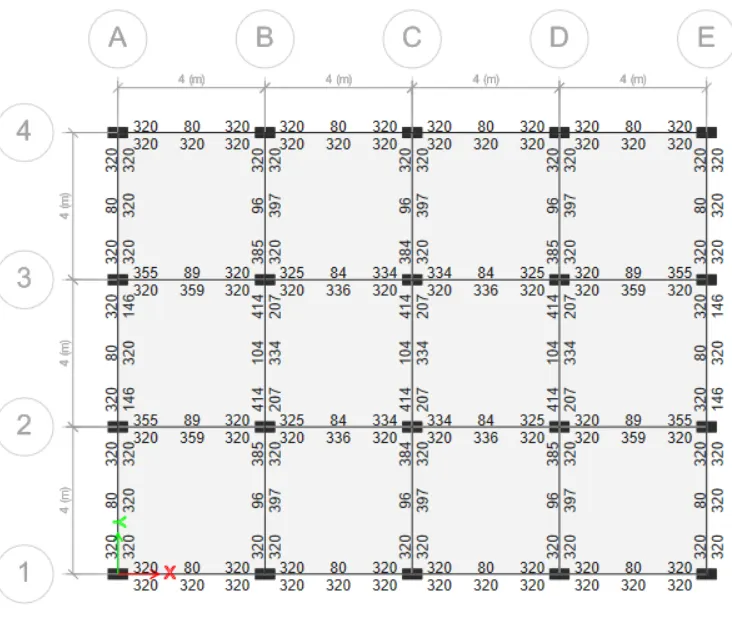
Shear Reinforcement
Go to concrete frame design>design beam info>shear reinforcing> apply