Project 1_Comparative study of different storey buildings for Seismic forces
Aim - To do comparative Analysis of different storey buildings for Seismic forces
Introduction:
1) ETABS is an engineering software product that caters to multi-story building analysis and design
2) Modeling tools and templates, code-based load prescriptions, analysis methods and solution techniques, all coordinate with the grid-like geometry unique to this class of structure.
3)Basic or advanced system under static or dynamic conditions may be evaluated using ETABS.
4)For a sophisticated assessment of seismic performance,modal and direct-integration time-history analyses may couple with p-Delta and Large Displacement effects.
5)Different building geometries behave differently when induced bt the same seismic forces.
6)Hence,it is very important to properly understand the response of buildings related to their structural configuration for a safer design approch.
7)Therefore in this project, we have modeled different buildings with varying geometries using ETABS.
8)Furthermore, their responses are analyzed with the help of the software and the results
are then compared to graps an understanding of the structural behavior of buildings with different storeys.
Structural Element Sizes - For Building type A
- Beams - 300x400 mm
- Columns - 400x400 mm
- Slab - 150 mm
Material Properties
- Grade of concrete - M30
- Grade of steel Reinforcement Bars - Fe 415
- Dead Load on beams from infill wall - 10kN/m
- Live load on floor - 3kN/m2 (Assume same for roof floor also)
Procedure:
- For Building type A
Step1:
- Open the ETABS software from desktop icon
- Once software is open click on new model
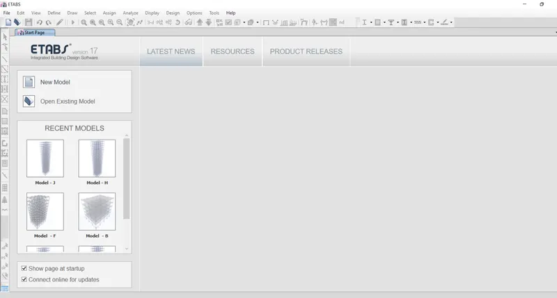
Step2:
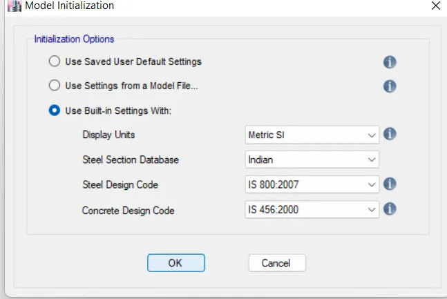
- Once you click on new model
- A model Initialization setting will open
- Select metric SI units
- Select section database Indian
- Select Steel Code IS 800-2007
- Select Concerete design code IS 456-2000
Step3:
- Once you click okay
- A following dialogue box of grid setting will open
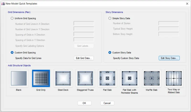
- In New Model Quick templates under grid dimensions select the custom grid spacing
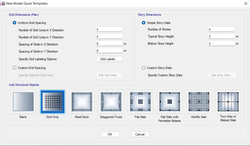
- Once you click on custom grid spacing
- Click on display grid data as spacing
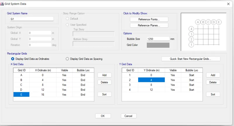
Step4:
- In New Model Quick templates under Story dimensions
- Select the custom story data and then click edit data.
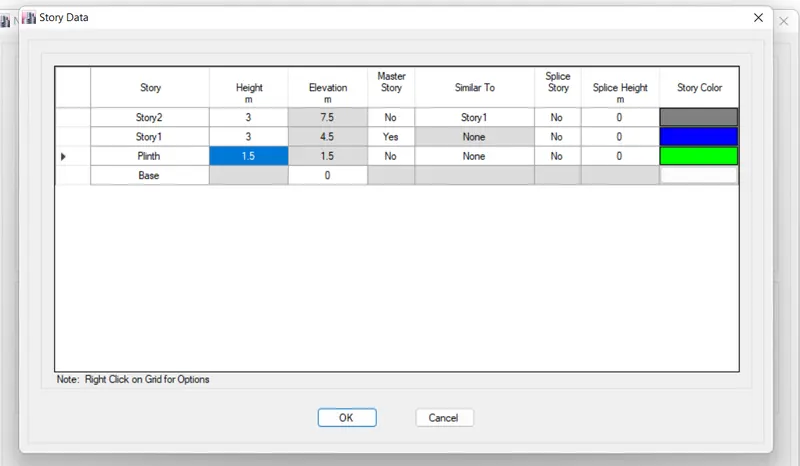
- Now input the storey details
- As given in question and Story1 was selected as the Master story
- Click on okay.
Step5:
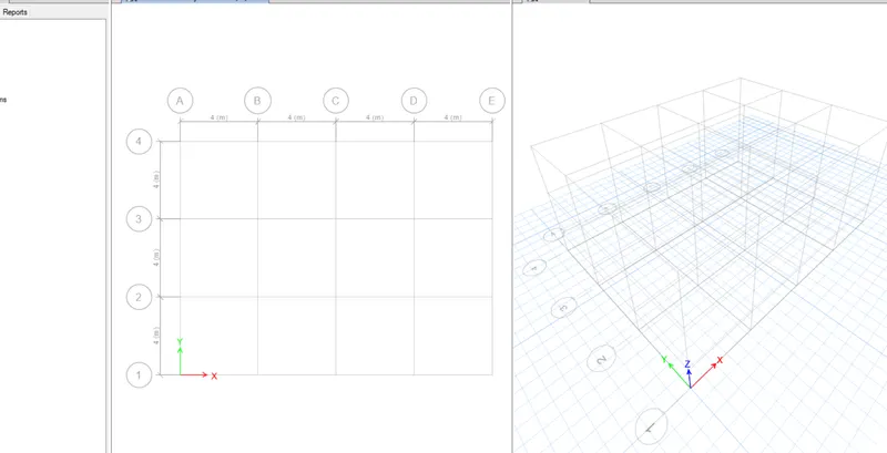
- Once you click on okay
- A plan and 3D view of model is created in model space
Step6:
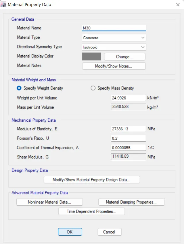
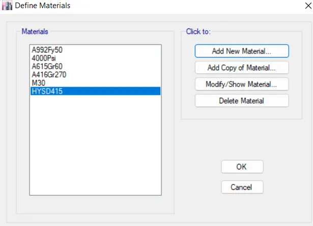
- Now we have to define the materia properties
- click on define click on material properties
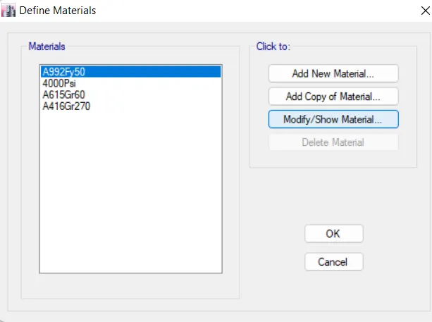
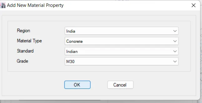
- Add New material as Concrete
- Select Grade of concrete M30
- Standard as Indian
- Click OK
- The remaining data is as per IS Code
Step7:
- Similarly we have to define the material properties for steel
- Click on define
- Click on material properties
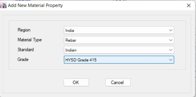
- Select New material as Rebar
- Select Grade of Steel HYSD Grade Fe415
- Standard as Indian
- Click on Ok
- The remaining data is as per IS Code
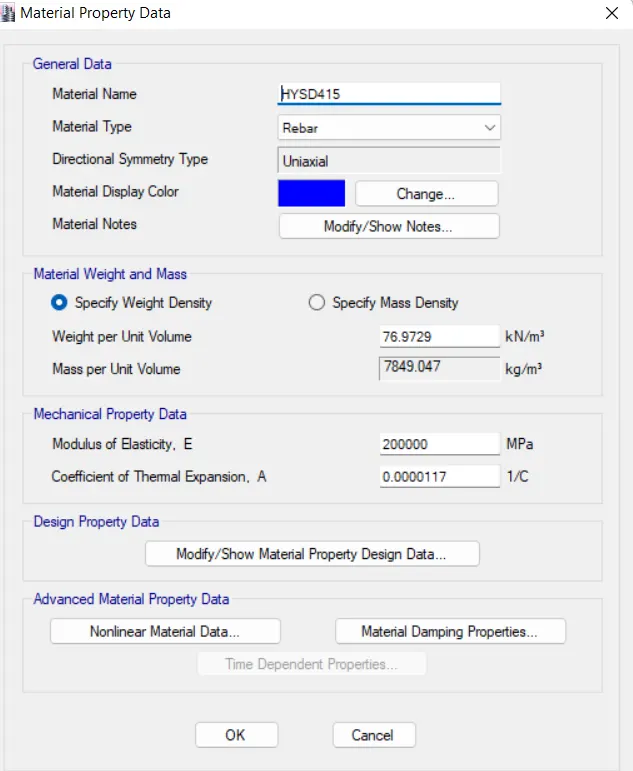
- Material properties is added
Step8:
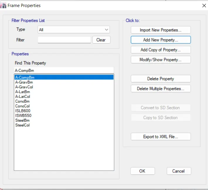
- Now we have to define the section properties (Column and beam)
- Click on define
- Select Section properties
- Click on Frame Section
- Click on concrete Rectangular
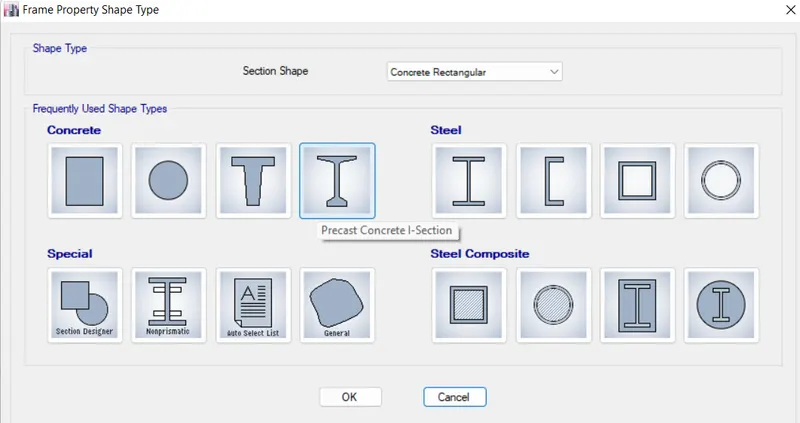
- Click on add new property
- Give property name Beam 300x4000
- Material type M30
- Section shape Concrete Rectangular
- Depth 400 mm
- Width 300 mm
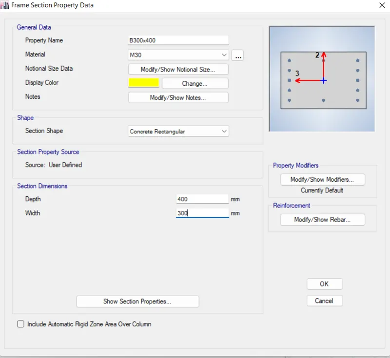
- Click on Modify/show Rebar
- Select M3 Design only (Beam)
- Select the rebar materials as HYSD Fe415 in both the direction
- Click on ok
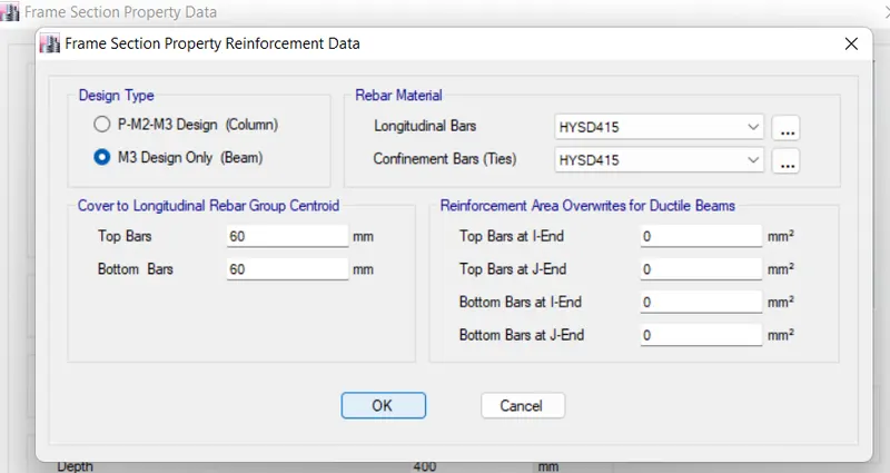
- Similarly we have to follow the same steps for Column also.
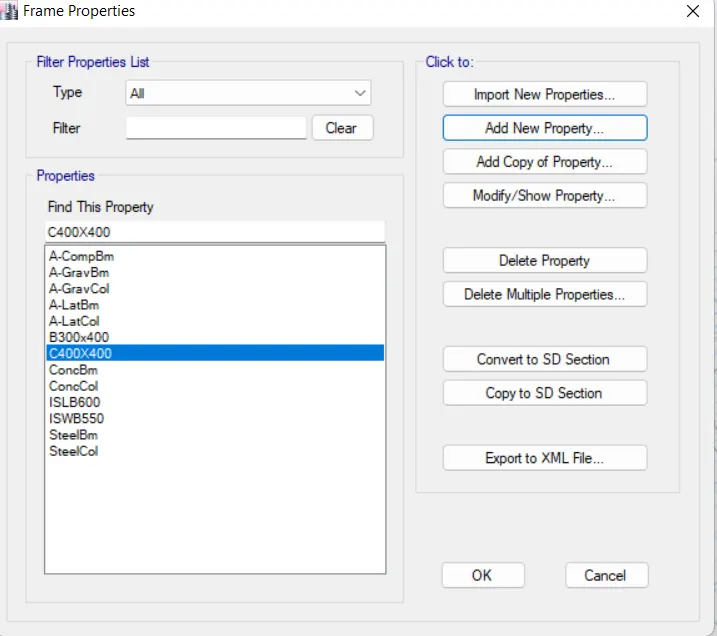
- Property name Column 400x400mm
- Material M30
- Depth 400
- Width 400
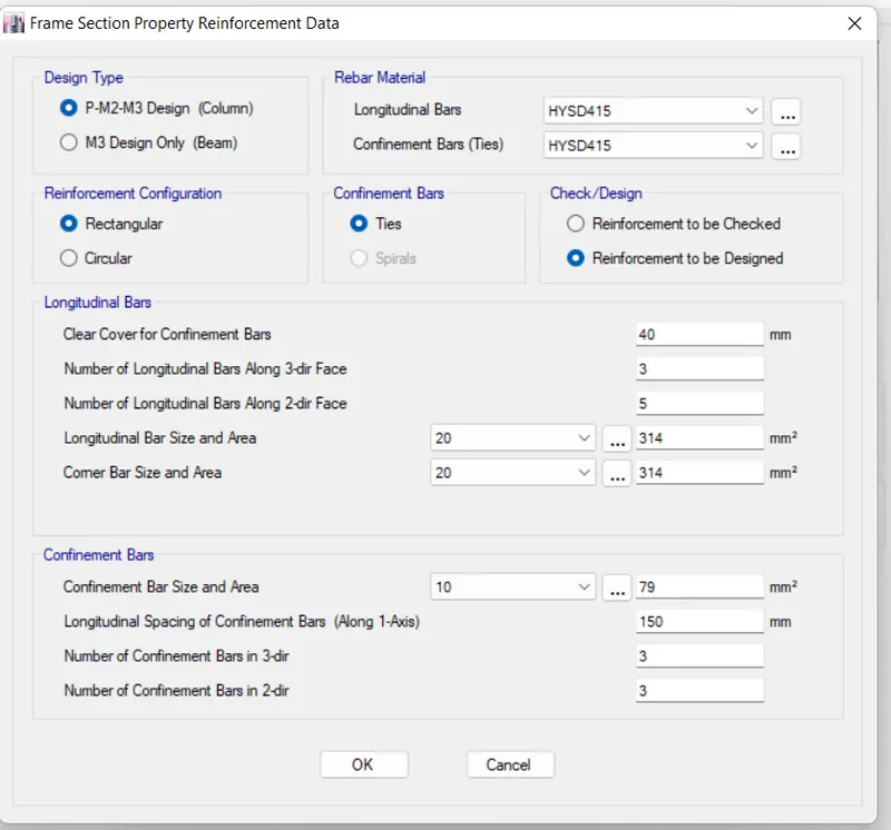
- Click on modify/show Rebar
- Select M3 Design Only (Column)
- Select the Reabr material as HYSD Fe415 in both the direction
- Click on Ok
Step9:
- Now we have to define slab properties
- click on define
- Select section properties Select Slab properties
- Click on slab section
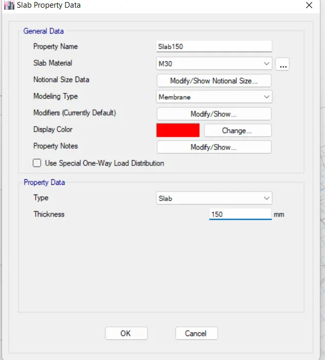
- Give property name Slab150
- Slab Material M30
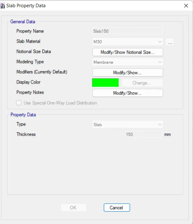
- Modeling type Membrane
- Type Slab
- Thickness 150 mm
Step10:
- Now we have keep the 3D view also to see the properties
- Now we have to add the columns and beams
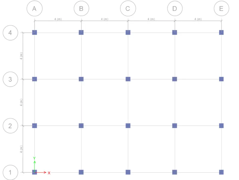
- Click on Quick Draw Column option
- Select the column properties which we have defined earlier
- Draw the columns at the grids as shown in below
- Note that All stories option should be selected which is at the bottom
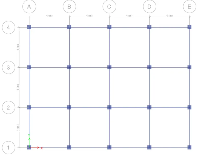
- Similarly we have to draw beams also
- Select quick draw beam option
- Select beam properties which we have defined earlier
- Draw the beam as shown below
Step11:
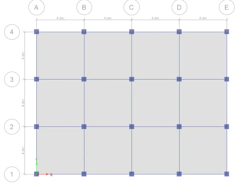
- Now we have to add slabs
- Select wuick draw floor
- Draw the slabs as shown below
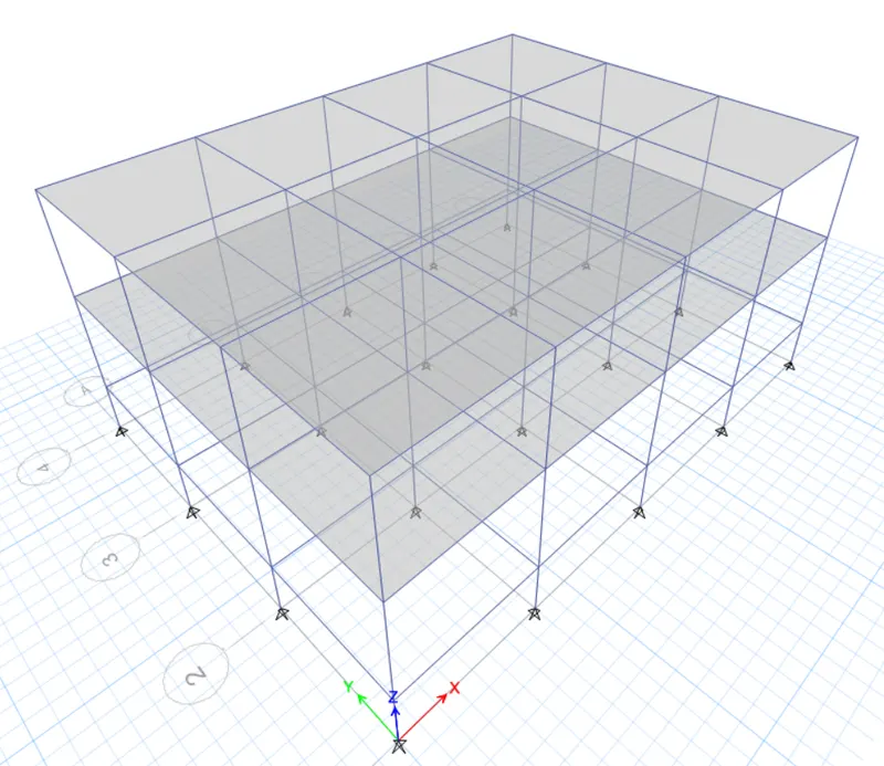
- 3D view after assigning the material and section properties
Step12:
- Now we have to assign the loads
- Select Define
- Click on load patterns
- Define load pattern dialogue box will open
- Add the following loads and select the IS code for seismic case as IS -1893
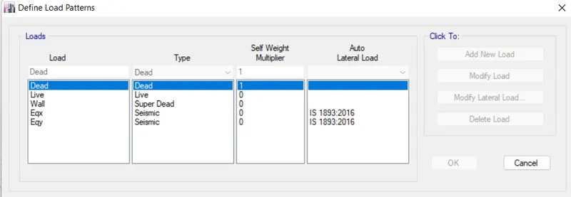
Step14:
- Now we have t apply the live loads
- In Assign menu select shell loads
- Click on Uniform loads
- Load pattern as Live load
- Load - 3kn/m2
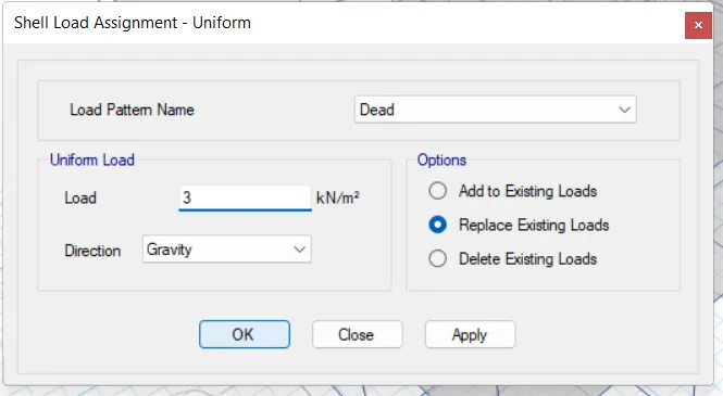
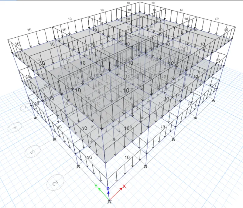
- We can see that floor loads has been assigned to all the floor
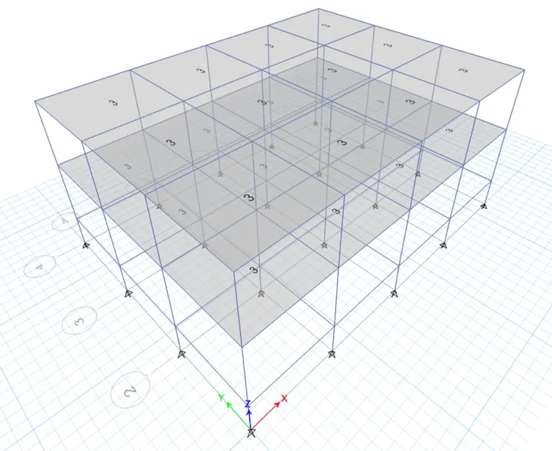
- Now we have to assign wall load for beams
- Select assign
- Click on frame loads Uniformly distributed loads
- Select load pattern as wall
- Apply 10kn/m load
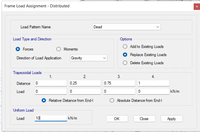
- Load has been assigned
Step15:
- Now we have to assign Mass source for modal calculations
- Click on Define menu
- Select mass source options
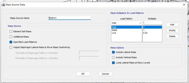
- Mass source dialogue box will open
- Add the loads
- Dead load 1
- Wall 1
- Live load 0.25 ( Because we only considered some fraction of live load in calculation of seismic weight)
- So, live load upto 3Kn/m2 : 25%
Above 3Kn/m2 : 50%
Step16:
- Now we have to assign load combinations
- Forthat click on define menu
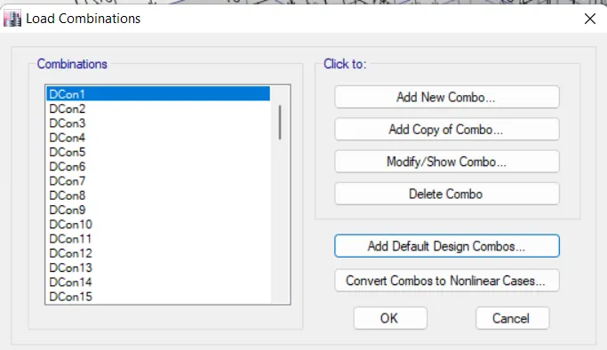
- select load combinations
- load combination box will open
- Click on add default Design Combos
Step17:
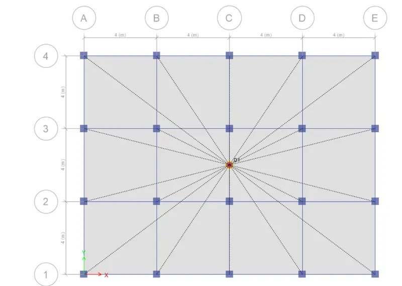
- Now we have to assign Diaphragm
- Click on assign
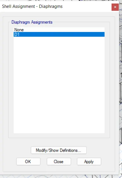
- Select shell Select Diaphragm
- select D1
- Click on apply
- Click on Ok
- A diaphragm has been assigned
Step18:
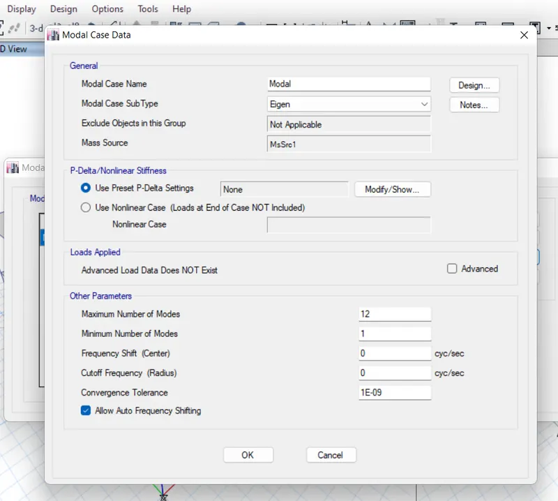
- Now we have to create a Model Analysis
- Click on Define
- Select Modal cases
- Click on Modify
- Load Case Name - Modal
- Load case type-Eigen
- Mass Source Which we have already defined
- Click on Ok
Step 19:
- Before Run Analysis we have to check the model
- Click on Analyse
- Click on Check Model
- A structure is verified without any error and Model has been checked.

Step 20:
- Now Click on Run Analysis
- Once the analysis is done you will see the deform shaped as below

Step 21:
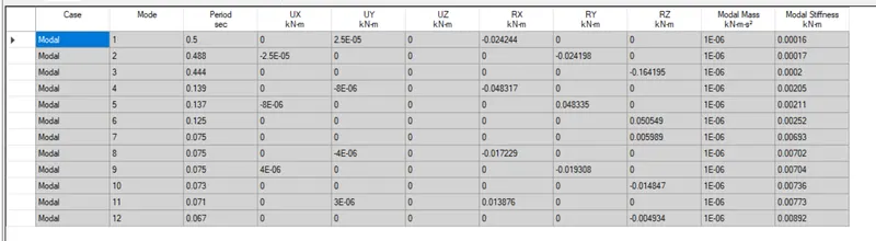
- Now we have to check the mock as per: IS 1893.
- For that click on Display Show tables:
- For Building Type - D
Step 1:
- For Building type 8 we don't need to follow the same steps
- Just make a copy of building A and Save it as Building B
Step 2:
- Edit the Story data as follows- (which are given)
- 5-rory building
- Farm 300mm x 400 mm
- Column: 400mm x 400 mm
- Grade M3D-FA 419.
- Brick wall load kN/m
- Live load 8 KN/m2
Step 3:
- Click on new file, go to edit – story and grid data.
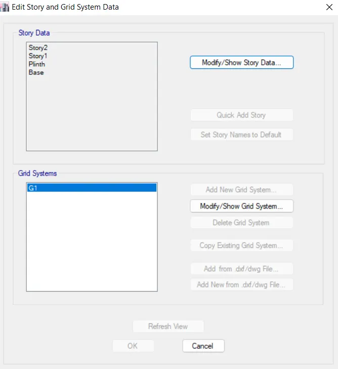
- Click on the modify story data option
- Then right-click on the top story and select the add story option
- Set the height and the number of storeys you want to odd.
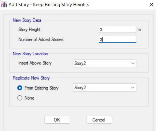
- In our case, we need to add 3 more floors to convert our 2story building into a 5 story one.
- Also, make sure to make each story similar to the master story created in Model A.
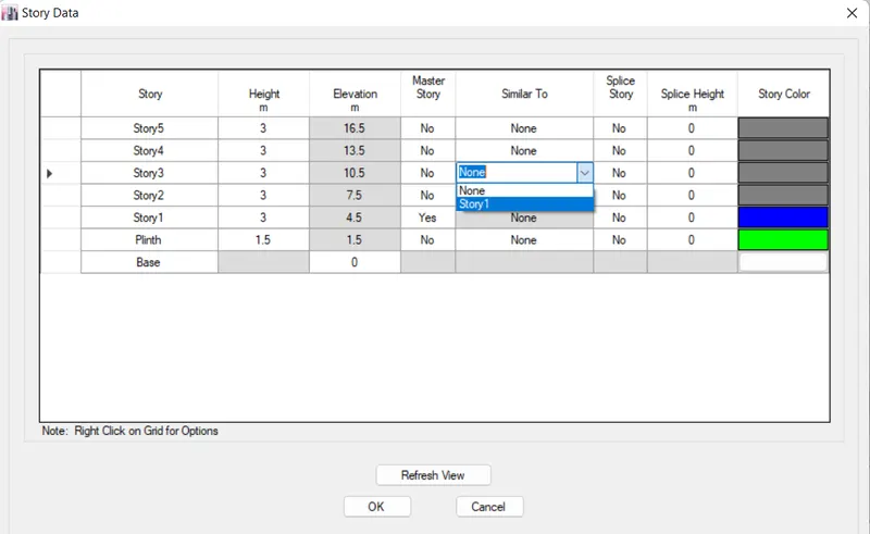
- Click on okay
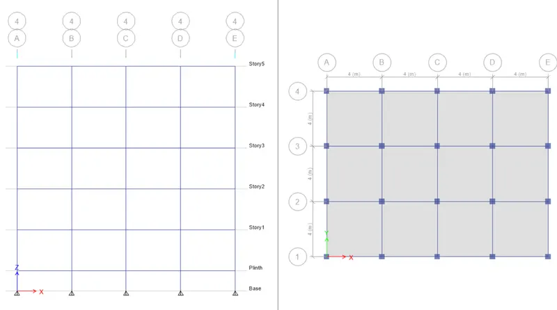
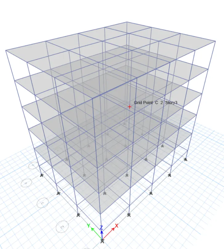
- A 3D view of 5 storey model
Step 4:
- Before Run Analysis we have to check the model
- Click on Analyse
- Click on Check Model
- A structure is verified without any error and Model has been checked.
Step 5:
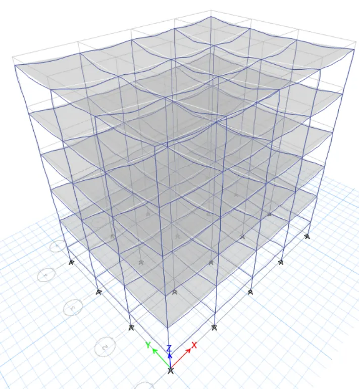
- Now Click on Run Analysis
- Once the analysis is done you will see the deform shaped as below
Step 6:
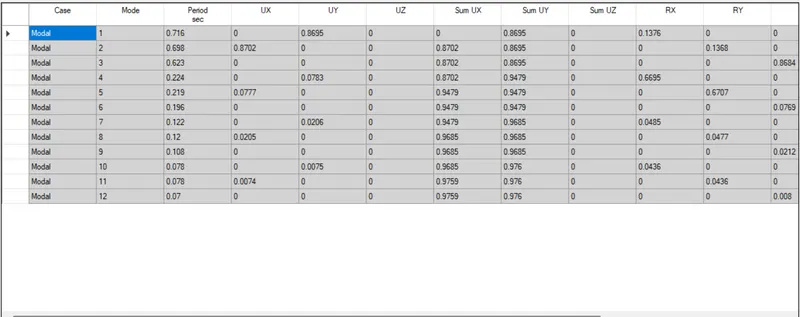
- how we have to check the mock as per is 1893.
- For that click on Display – Show tables
- For Building Type-C (G+5 with column orientation in X-direction)
Step 1:
- For Building type C we just need to edit the Column Orientation
- Just make a copy of building B and Save it as Building C
Step 2:
- Edit the Story data as follows - (which are given)
- 5-story building
- Beam: 300mm x 400 mm.
- Column: 550 mm x 300 mm
- Grade M30-Fe 415.
- Brick wall load = 10 kn/m
- Live load 3 KN/m^2
Step 3:
- Edit the Column Size and Orientation
- Click on Edit - Column section
- Click on Define-section properties -frame section.
- Select the previously created column for building A and B.
- Click on the modify/show properties option.
- Rename the column as 550mmx300mm.
- Enter the depth and width of columns
- So, select the column section
- Then Click on assign
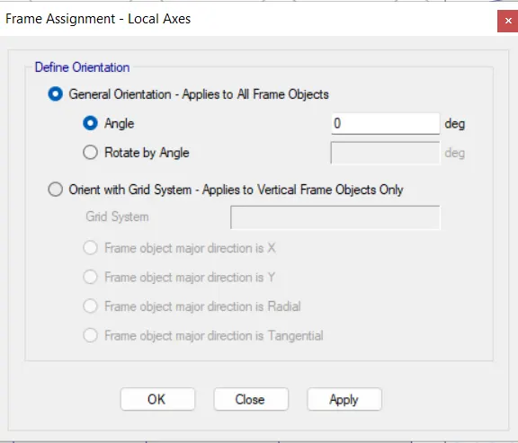
- Select Local axis-rotate it by 90 degrees.
- This way, all the columns shall be oriented in the X-direction meaning 550mm laying down in the x direction.
Step 4:
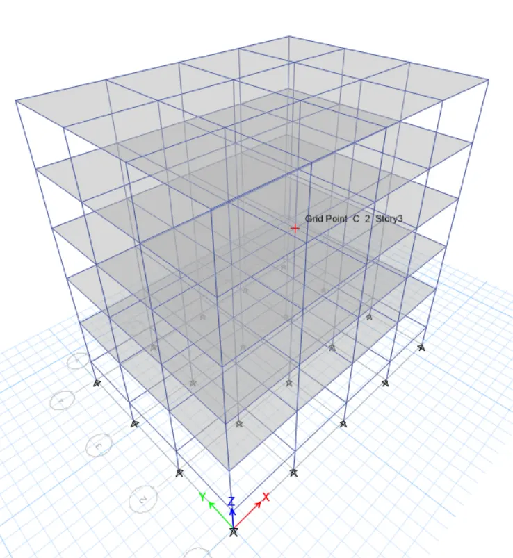
- Once you click on Ok
- The columns will be oriented in X direction
Step 5:
- Before Run Analysis we have to check the model
- Click on Analyse
- Click on Check Model
- A structure is verified without any error and Model has been checked.

Step 6:
- Now Click on Run Analysis
- Once the analysis is done you will see the deform shaped as below
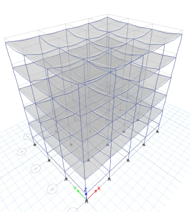
Step 7:
- Now we have to check the mode as per IS 1893.
- For that click on Display - Show tables
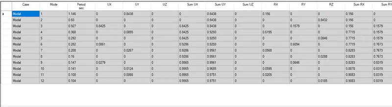
- For Building Type -D (G+5 WITH COLUMN ORIENTATION IN THE Y DIRECTION)
Step 1:
- For Building type D we need to edit the Column Orientation
- Just make a copy of building C Save it as Building D
Step 2:
- Edit the Story data as follows - (which are given)
- 5-story building
- Beam: 300mm x 400 mm
- Column: 300 mm X 550 mm
- Grade M30-Fe 415.
- Brick wall load = 10 kn/m
- Live load 3 KN/m^2
Step 3:
- In this model, we don't need to edit the column dimensions other than the column orientation.
- The sizes of the column will remain the same
- But we have to shift the column orientation from X to Y direction.
- Then, select the column section
- Click on Assign - Select the local axes and bring the origin back to 0.
- Therefore, all the columns shall be oriented in the Y-direction.
Step 4:
- Once you click on Okay
- The columns will be oriented in Y direction
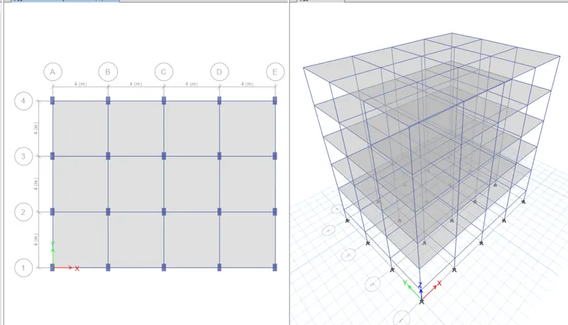
Step 5:
- Before Run Analysis we have to check the model
- Click on Analyse
- Click on Check Model
- A structure is verified without any error and Model has been checked.
Step 6:
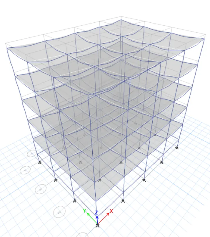
- Now Click on Run Analysis
- Once the analysis is done you will see the deform shaped as below
Step 7:
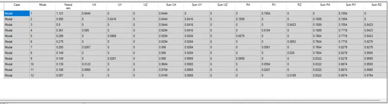
- Now we have to check the mode as per IS 1893
- For that click on Display – Show tables
- For Building Type-BUILDING "E" (G+10)
Step 1:
- We have to create a New Model
- For that make a copy of Model D and save it as Model E
Step 2:
- Edit the Story data as follows-(which are given)
- 10-story building
- Beam: 300mm x 400 mm
- Column Bottom 5 (600 mm x 600 mm
- Top 5 400 x 400 mm)
- Grade M30-Fe 415
- Brick wall ion= 10 kn/m
- Live load 3 KN/m^2
Step 3:
- Once you save the Model D as Model E
- Edit the storey and add & more storey just like previously we have done
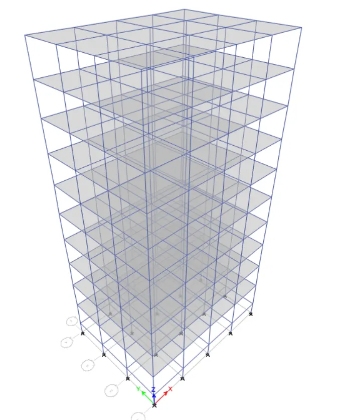
Step 4:
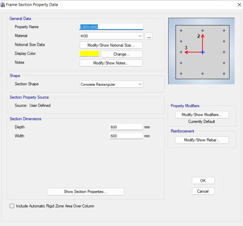
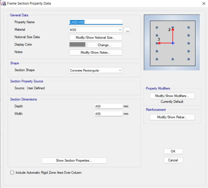
- Now we have to add the Different column section properties
- For Bottom storey-600mm x 600 mm
- For Top Storey-400mm x 400 mm
- And the properties in Column section
- Define Section-Frame Section and Add the properties
Step 5:
- so go to Visualise setting
- Select only Columns
- Untick the beams and columns
- So it will be easy for us
Step 6:
- Now we have to assign the properties to the bottom storey
- For that we have to set the limits for bottom floors and top floors
- for that go to Edit - Set building limits
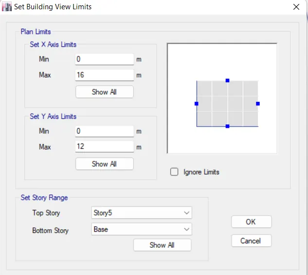
- The set building limit option in ETABS allows you to view only the floors that you need to work on.
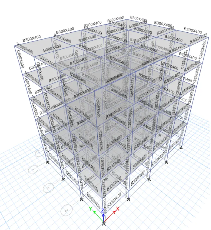
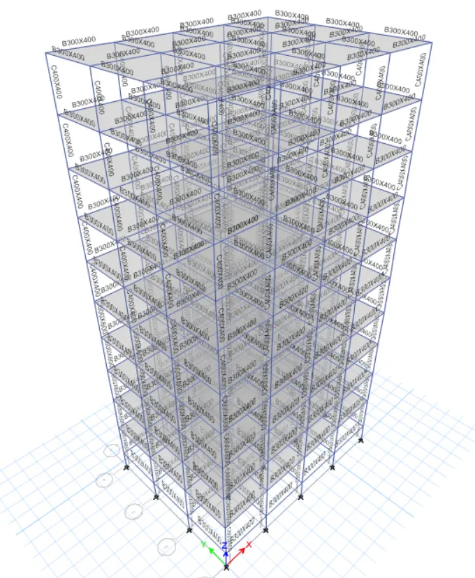
- Hence, first set the firm to bottom 3 select at column sand assign and assign them the required column section
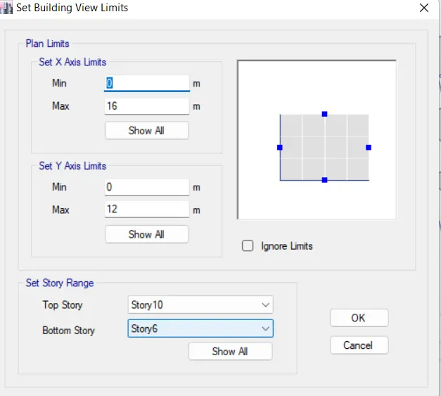
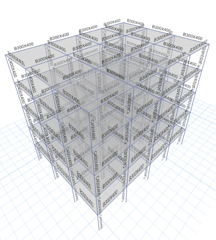
- Similarly repeat the procedure for the remaining top columns and complete with the model.
- Column 600 mm x 800mm has been assigned to bottom storey
- Set the building limits to Top floors
- Column properties has been assigned to the model
Step 7:
- Before Run Analysis we have to check the model
- Click an Analyse
- Click on Check Model
- A structure is verified without any error and Model has been checked
Step 8:
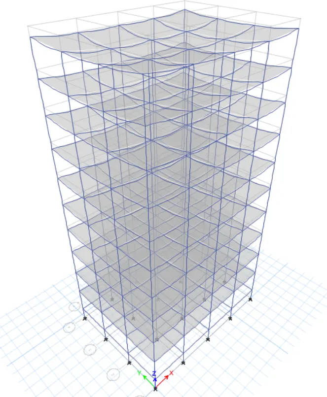
- Now Click on Run Analysis
- Once the analysis is done you see the deform shaped as below
Step 9:
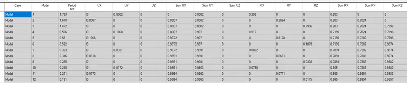
- Now we have to check the mode as per is 1893
- For that click on Display-Show tables
- For Building Type-BUILDING "H" (G+25)
Step 1:
- We have to create a New Model
- For that make a copy of Model G and save it as Model H
Step 2:
- Edit the Story data as follows-(which are given)
- 25 story building
- Beam: 300mm x 400 mm
- Column (600 mm x 800mm)
- Brick wall loop-10 Kn/m
- Live load 3 KH/m^2
Step 3:
- Once you save the Model as Model H
- In this mode we don't need to edit too much
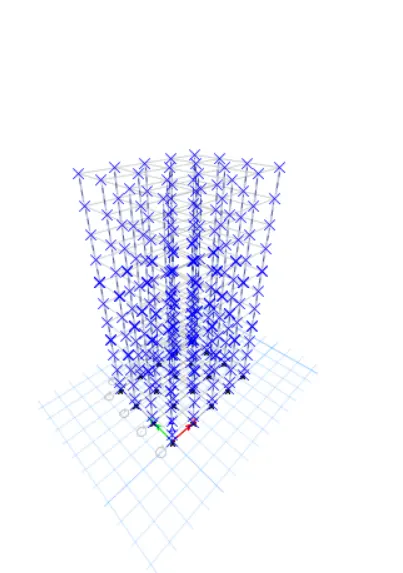
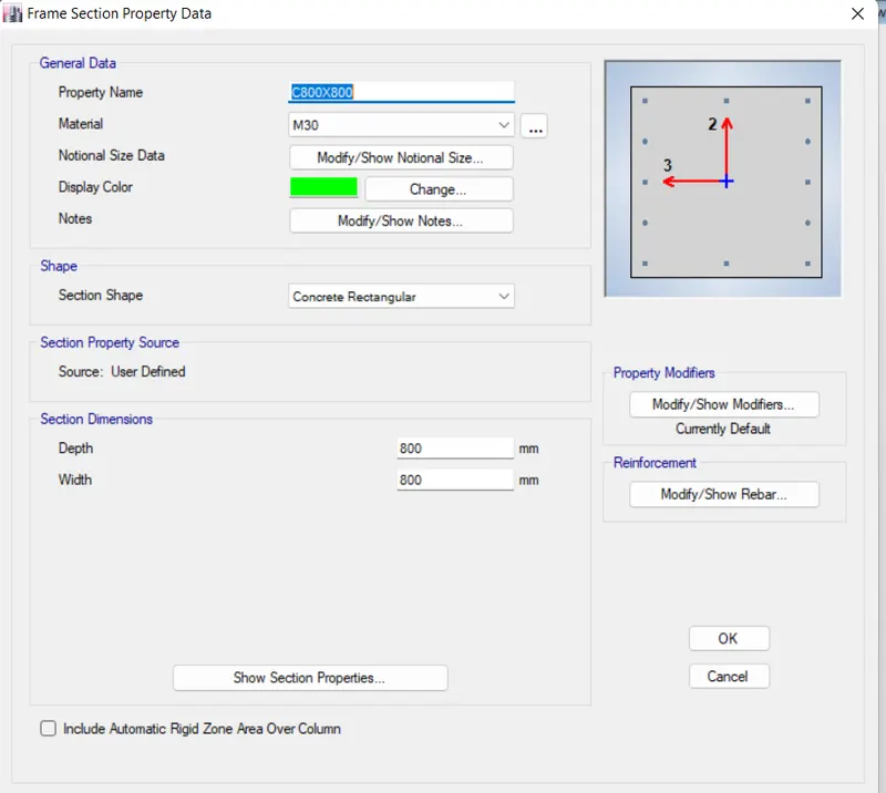
- We just need to change the Column properties as (800mm x 800mm) which is uniform
Step 4:
- Only we have to edit that Column Size
- As it has Uniform Column Size (800 mm x 800mm)
- Properties are already added in section properties
Step 5:
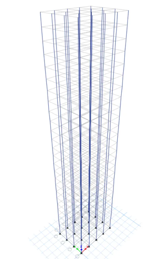
- So go to Visualise setting
- Select only Columns
- Untick the beams and
- So it will be easy for us columns
Step 6:
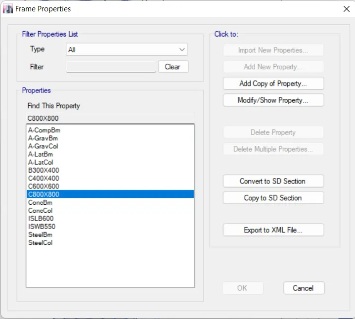
- Now we have to assign Column to the model
- Select all the column from Select Object type - Column
- Select the properties (800mmx 800 mm)
- Click on Okay.
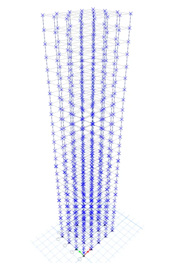
- Column properties has been assigned to the model.
Step 7:
- Before Run Analysis we have to check the model
- Click on Analyse
- Click on Check Model
- A structure la verified without any error and Model has been checked
Step 8:
- Now Click on Run Analysis
- Once the analysis is done you will see the deform shaped as below
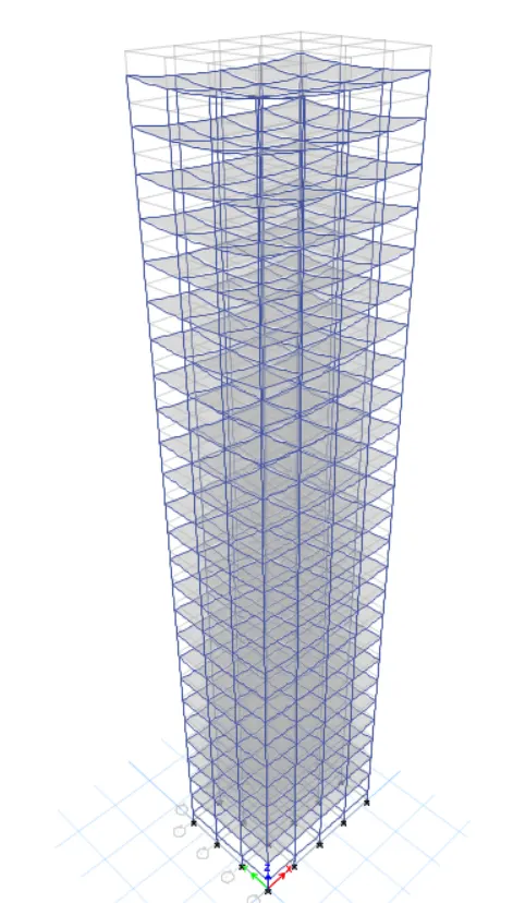
Step 9:
- Now we have to check the mods as per is 1893.
- For that click on Display-Show tables
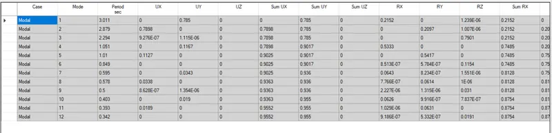
- For Building Type-BUILDING J (+25)
Step1:
- We have to create a New Model
- For that make a copy of Model H and save it as Model J
Step 2:
- Edit the Story data as follows-( which are given) )25-story building )
- Beam: 300mm x 400 mm.
- Column: (300 mm X 800 mm)
- Grade M30 - Fe 415.
- Brick wall load-10 kn/m
- Live load 3 KN/m^2 (increased the load by 10%)
= 3 x 10%
= 0.3
- Therefore, total Live Load = 3.3 kn/m
- In case of Mass Source Take the live load as 0.50
- Live load 0.50 (Because only considered some fraction of Live load in calculation of seismic weight)
- So live load, upto 3 Kn/m2 - 25%
Above 3 Kn/m2 - 50%
Step 3:
- Model J is similar to the Model H
- So we do not have to edit the anything regarding properties
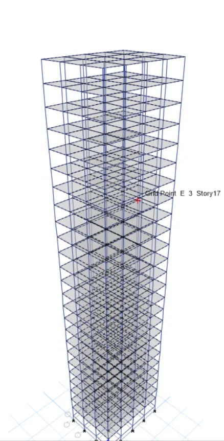
- Only we have to increase the Live Load by 10%.
- For that Select the Slab-Select Object type - Slab 150
Step 4:
- Now we have to edit the Load
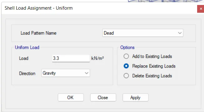
- For that Cilek on Assign Shell Loads - Click On Uniform Load
- Click on Replace the Existing Load
- Enter the load -3.3 kn/m2
- Check If load is applied or not
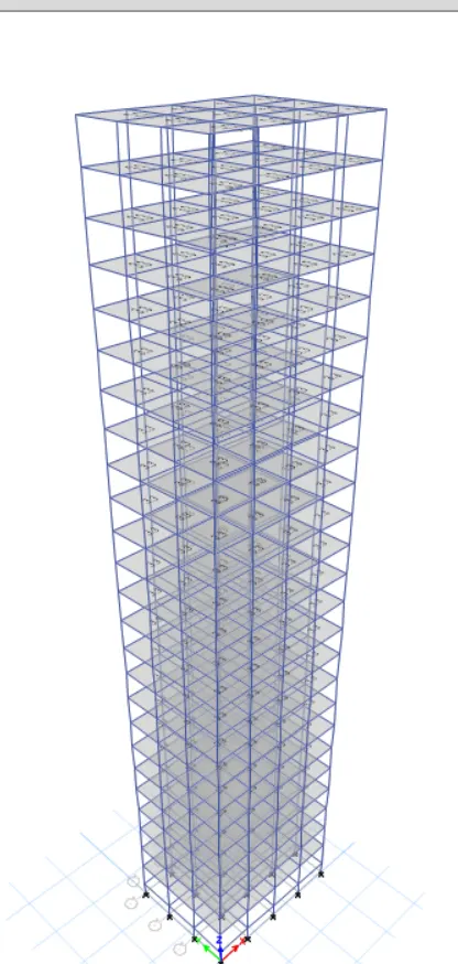
Step 5:
- Before Run Analysis we have to check the model
- Click on Analyse
- Click on Check Model
- A structure is verified without any error and Model has been checked.
Step 6:
- Now Click on Run Analysis
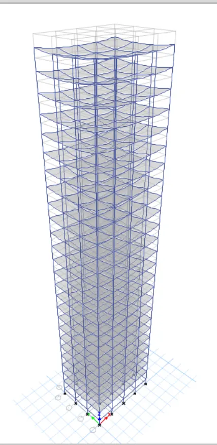
- Once the analysis is done you will see the deform shaped as below
Step 7:
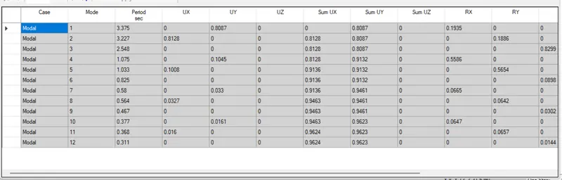
- Now we have to check the mode as per IS 1893.
- For that click on Display-Show tables
- For Building Type-BUILDING "K"
Step 1:
Step 2:
- Edit the Story data as follows - (which are given)
- 25-story building
- Beam: 300mm x 400 mm
- Column: (800 mm x 800 mm)
- Grade M30 - Fe 415
- Brick wall load=10 kn/m
- Live load 3 KN/m^2 (increased the load by 20%)
= 3 x 20%
= 0.6
- Therefore, total Live Load = 3.5 kn/m
- In case of Mass Source - Take the live
- load as 0.50 viii) Live load - 0.50 (Because we
- only considered some fraction of Live
- load in calculation of seismic weight
- So live load, upto 3 Kn/m2 - 25%
above 3 kn/m2 - 50%
Step 3:
- Model K is similar to the Model J
- So, we do not have to edit the anything regarding properties.
- Only we have to increase the Live Load by 20%
- For that Select the Slab Select Object Type-Slab 150
Step 4:
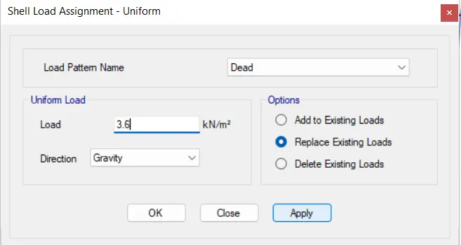
- Now we have to edit the Load
- For that Click on Assign - Shell Loads
- Click On Uniform Load
- Click on Replace the Existing Load
- Enter the load-3.6 Kn/m2
Stop 5:
- Before Run Analysis we have to check the model
- Click on Analyse
- Click on Check Model
- A structure is verified without any error and Model has been checked.
Step 6:
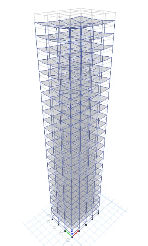
- Now Click on Run Analysis
- Once the analysis is done you will
- see the deform shaped as below
Step 7:
- Now we have to check the mode as per IS 1893,
- For that click on Display-Show tables
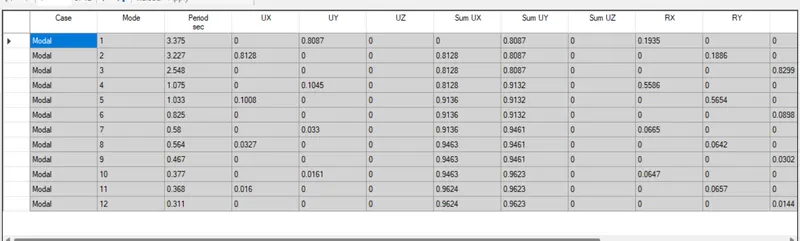
- Results-All the 10 buildings were modelled and analysed successfully.
A] Effect of stiffness on T: Compare fundamental nature periods of building E&F as well as G & H.
Why id there a marginal or significant difference in the fundamental natural periods?
| Model Type | No of Stories | Column configuration | Results | Conclusion |
| Building E | 10 |
Upper 5 stories = 400x400 mm Bottom 5 Stories = 600x600 mm |
As we could see that by changing the column sizes there will not be any effect on Natural period, it remains Same | |
| Building F | 10 |
Column Size = 600x600mm Uniform throught Building |
As we could see that in Building H has uniform column section but it has more natural time period |
|
| Building G | 25 |
Column Sizes Bottom 10 story (800x800 mm) Upper 10 story (600x600 mm) Top upper 5 story (400x400 mm) |
Where as building G has large column at its base and reduces as we go higher level. But it has less natural time period as compared to H = ___ |
|
| Building H | 25 |
Column size = 800x800 mm Uniform throught Building |
So we can conclude that providing larger size of column at base and reducing the size at higher level will reduces the Natural time period |
B] Effect of mass on T: Compare fundamental natural periods of buildings H,J and K. Have the buildings become more flexible or stiff due to change in mass
| Model Type | No of stories | Percentage increase in Load (Mass) | Result | Conclusion |
| Building H | 25 | Load is taken as 3KN/m2 | As we could see that time period is increase as we increase the load or mass | |
| Building J | 25 | Load Increase by 10% (3.3kn/m2) | Therefore time period is directly proportional to the mass of the building | |
| Building K | 25 | Load Increase by 20% (3.6kn/m2) |
C] Effect of building Height on T: How does the fundamental natural periods of Buildings A,B,F and H change with change in building height?
| Model Type | No of stories | Height of Building | Results | Conclusion |
| Building | 2 | 7.5 m |
As we could see that the height of the building increases the natural time period is also increases Therefore, the natural period 'T' is also directly proportional to the building height |
|
| Building B | 5 | 16.5 m | ||
| Building F | 10 | 31.5 m | ||
| Building H | 25 | 46.5 m |
D] Effect of column orientation on T: How does the fundamental natural periods of building B, C and D change with change in column orientation?
| Model Type | No of dtories | Column orientation | Results | Conclusion |
| Building B | 5 |
Equal in Both Direction 400x400 mm |
As we could see that when column is orientad in X and Y direction in Time period | |
| Building C | 5 |
In X direction 550x300 mm |
So we can say that in Y direction Lateral Displacement is more as compared to X direction | |
| Building D | 5 |
In Y direction 300x550 mm |
E] Effect of flexural stiffness of structural elements on mode shapes: Compare fundamental mode
shape of building B in two situations when the flexural stiffness of beams relative to that of adjoining columns is very small versus it is large
| Model Type | No of stories | Flexural stiffness of beam | Results | Conclusion |
| Building B | 5 | 100% | If you decrease the flexural stiffness of beams,the overall flexural strenght of the beam is also going to reduce which increase the Natural period of time | |
| 10% |
F] Effect of Axial Stiffness of vertical Members on mode shapes: Compare the fundamental mode shape of building H in two situations when the axial cross-sectional area of columns is very small versus when it is large.
| Model Type | No of stories | Axial Stiffness of Columns | Results | Conclusion |
| Building H | 25 | 100% | As we axial stiffness of columns decrease, the fundamental natural period of the building increases regardless of its structural geometry | |
| 10% |
G] Effect of degree of fixity at column bases on mode shape: Compare the fundamental mode shape of Building B in two dituations when the base of columns is pinned versus when it is fixed.
| Model Type | No of stories | Base support | Result | Conclusion |
| Building B | 5 | Pinned |
As we can see that in pinned support natural time period is more as compared to fixed support. Therefore fixed support will provide more resistance as compared to pinned support |
|
| Fixed |