Project 1_Comparative study of different storey buildings for Seismic forces
Comparative study of different storey buildings for Seismic forces
AIM:
To done the modelling part for tye Buildings of A to K as per given details in the question and the figure show in below.
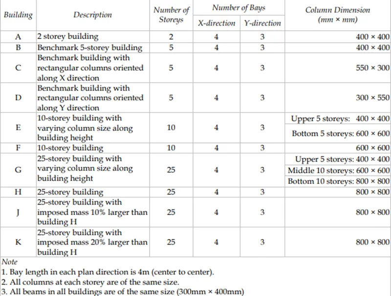
To carry out the all compartive studies of these buildings for sesmic forces.
INRODUCTION:
Each building has different numbers of natural frequencies at which offers the minimum resistance to shaking included by the external and internal effects.
Each of these diffrent natural freqencies and respectively its associated deformation shape of abuilding gives a natural mode of oscillation.
The each mode of oscillation haves the smallest natural frequency and largest natural period is called as the fundamental mode.The fundamental mode is always associated with natural period is called as Fundamental natural period.
If mode shape of oscillation associtaed with a natural period of a building is gives the deforned shape of the building.When it shkaen at the natural period. Hence we can say that the as per number of natural peroids have for the different mode shapes of the building.
In this comparative project we need to find out the effective of various parameters on natural period of the various types of the building.and also we can findout the mode shapes of oscillations for different type of buildings,and the details are given below.
- Factors affecting the natural period of the building as shown in the below:
- Effect of stiffness on T: Compare fundamental natural periods of buildings E & F as well as G & H. Why is there a marginal or significant difference in the fundamental natural periods.
- Effect of mass on T: Compare fundamental natural periods of buildings H, J and K. Have the buildings become more flexible or stiff due to change in mass.
- Effect of Building Height on T: How does the fundamental natural periods of Buildings A, B, F and H change with change in building height.
- Effect of Column Orientation on T: How does the fundamental natural periods of Buildings B, C and D change with change in column orientation.
- Factors influencing the mode shapes of oscillations of building as shown in below:
- Effect of Flexural Stiffness of Structural Elements on mode shapes: Compare fundamental mode shape of Building B in two situations when flexural stiffness of beams relative to that of adjoining columns is very small versus when it is large.
- Effect of Axial Stiffness of Vertical Members on mode shapes: Compare fundamental mode shape of Building H in two situations when axial cross-sectional area of columns is very small versus when it is large.
- Effect of Degree of Fixity at column bases on mode shape: Compare fundamental mode shape of Building B in two situations when base of columns is pinned versus when it is fixed.
PROCEDURE:
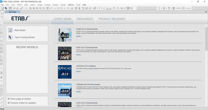
- Intially open the etabs software and click on the new model option.
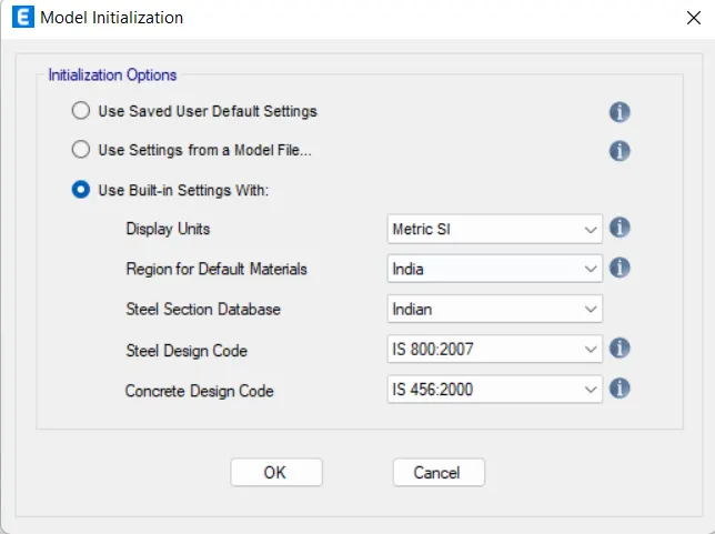
- It will appears a model initialization window, then select the Use Built-in settings with option and fill the units and codes as per the detailes we used.
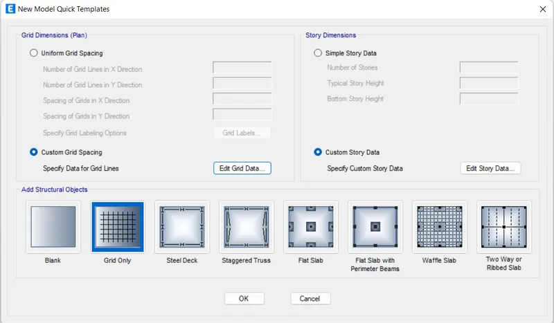
- Then again it will appear another window-New model quick template. BY using this tempate select the grids and storeys and respectivelty it dimensions also.
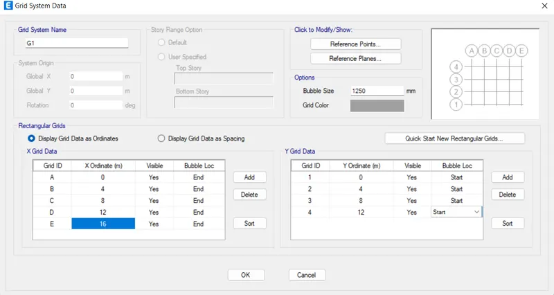
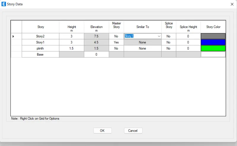
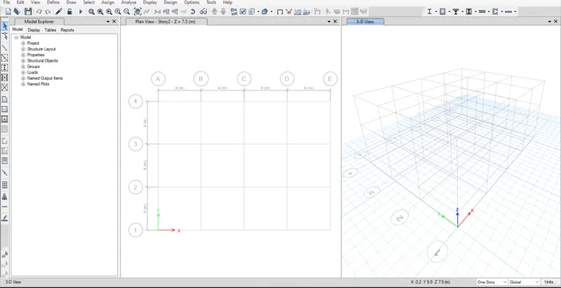
- Hence the grid and storey details will appear .
- After thet, we have done the material prooperties. So to input the material properties go to the Define tab and then select the materials property and then goto the add material property option.
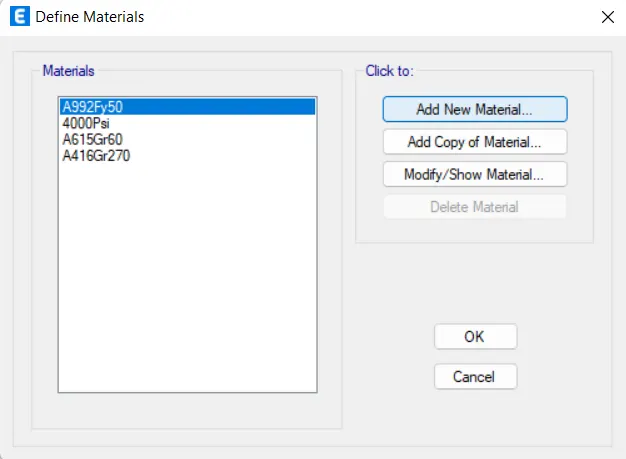
- Creating of concrete material as per the details given.
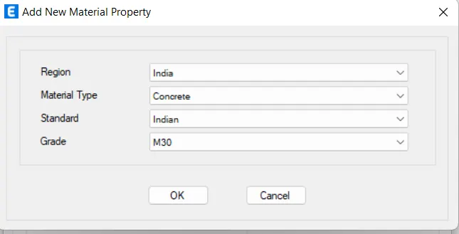
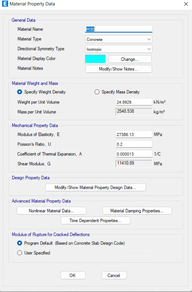
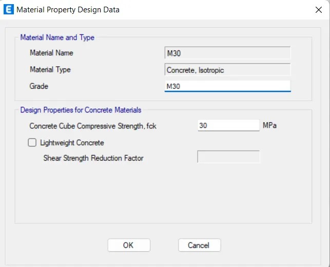
- After that Creating of Steel material as per the details given
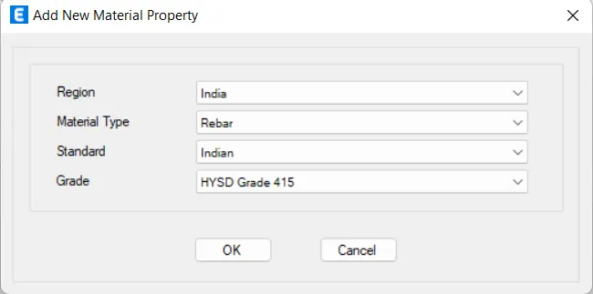
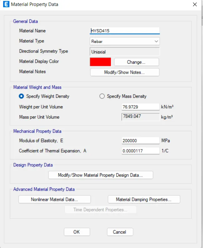
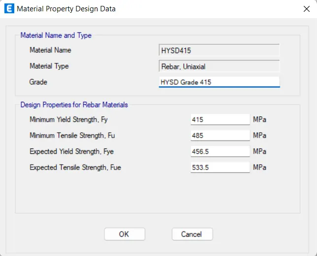
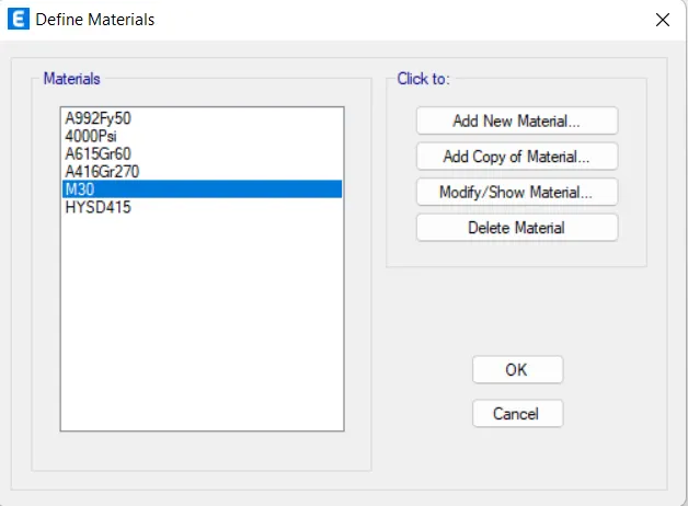
- Hence the materials are added and then click ok.
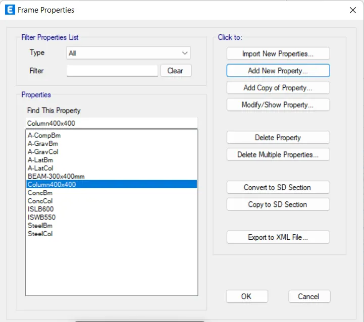
- Now we have to add the frames members to the strcture. So, We go define tab --> selection propeties--. frames sections.
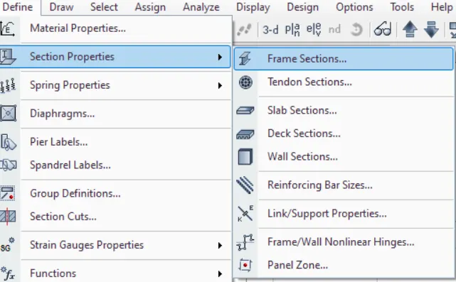
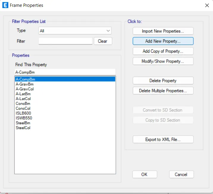
- NOw it will open the frame properties window . then click on the add new material property.
- NOw we have add the beam details, reinforcement details and cover to the reinforcement is also added.
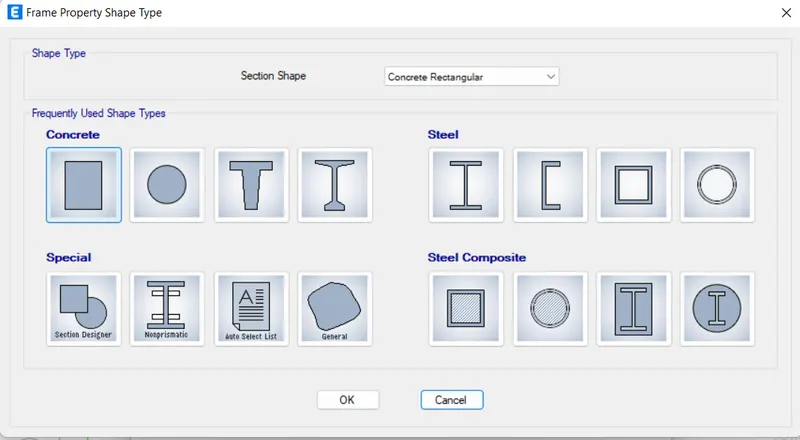
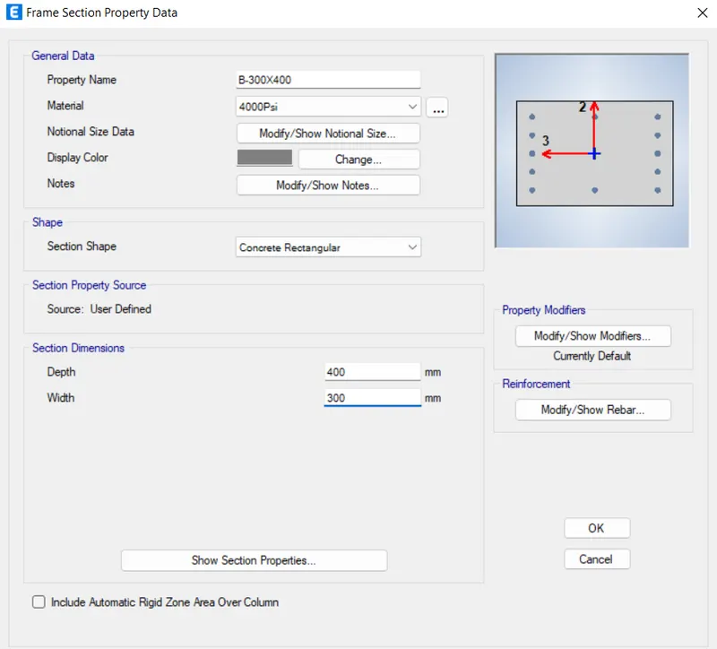
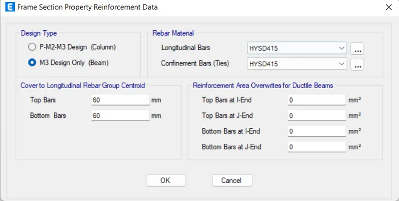
- Similarly, the deatils of columns are also filled.
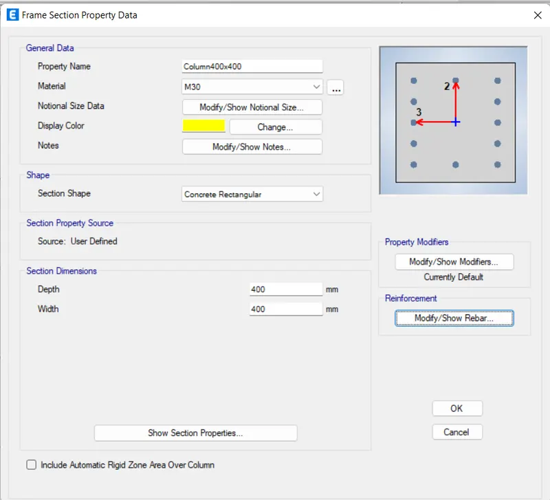
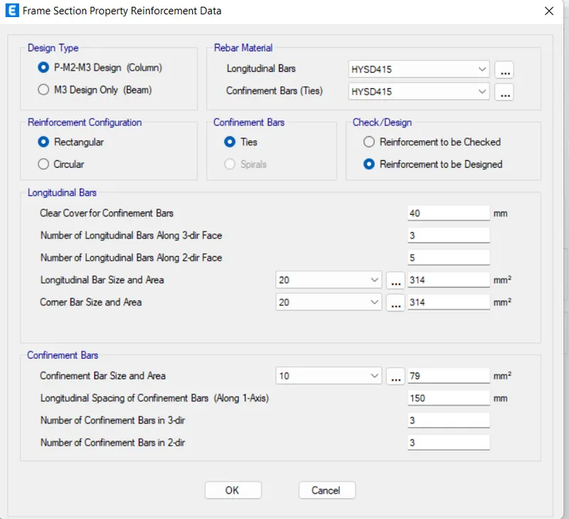
- Hence,The materials are added inthe frame window which is shown in the below figure.
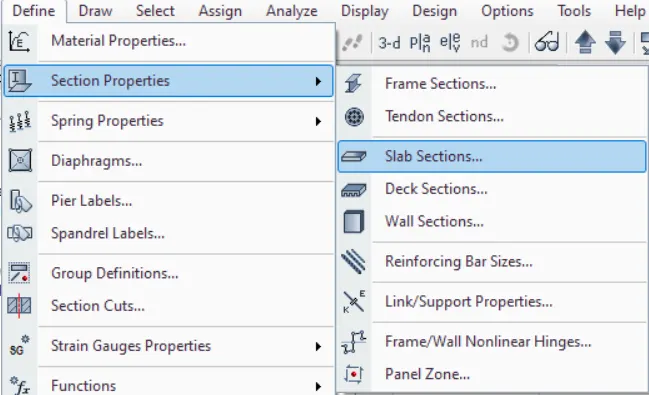
- Now, We have add the slab details. go to define tab- section property-slab sections-slab property data dailogue box opens. In that we have fill the detailes as per the question.
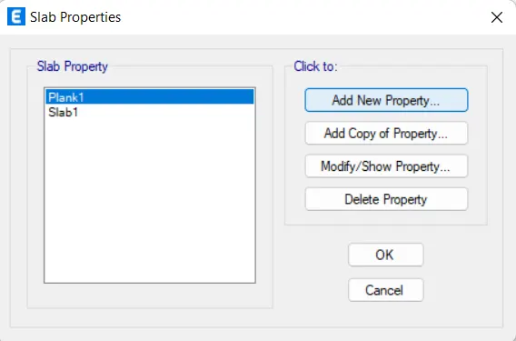
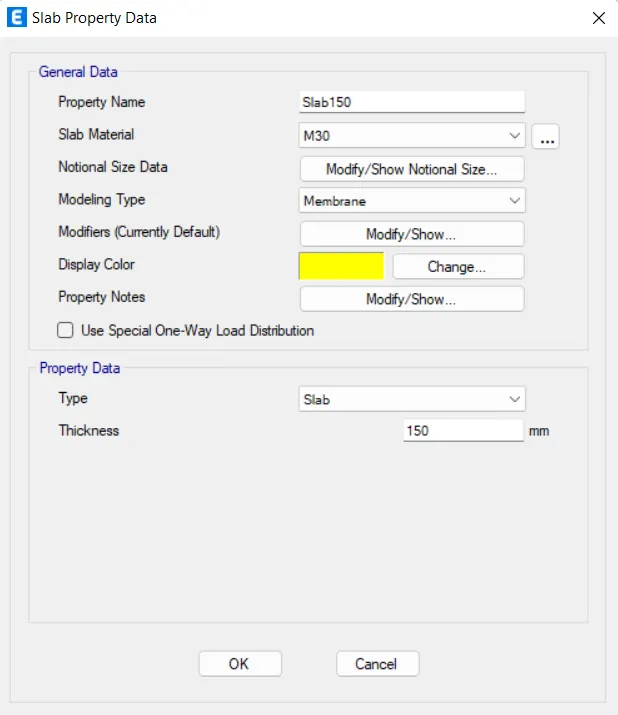
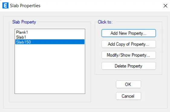
- All the properties for the frame members has added.so,we have to place the strctural members.i., beams,columns, and slabs.
- For adding the frame members to its. there is a tools which is placed left side of the etabs software.
- With the help of the tools all frame members are added.
- Firstly we have place the columns all over the storeys by taking the quick column slection tool.select the all column postions. it should be added automatically.
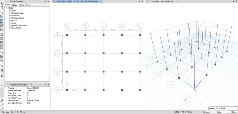
- Next we have place the beams by using the qucik beam selction tool.make sure that all beams are selected and it in all stories.
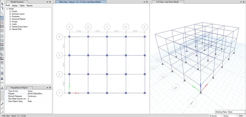
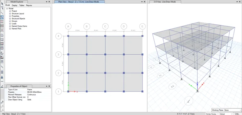
- Similarly the slabs are also slected.
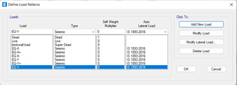
- Now, its time to assign the loads on the frames.FOr, go to define tab-load patterns- Define load patterns window will appear.Initially the dead and live are added onit self.no wwe have to added the brick wall load s and earth quakes load in both directions.
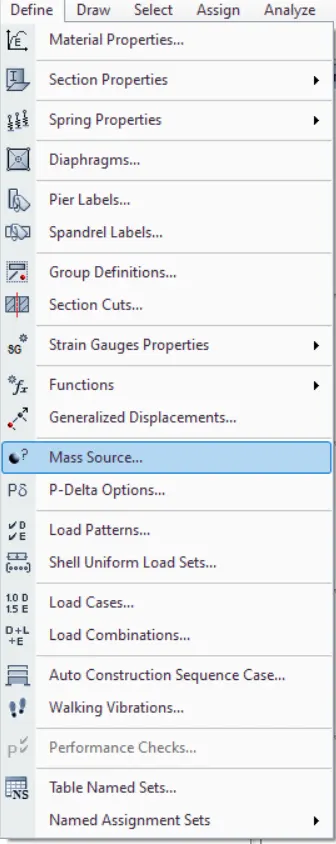
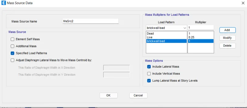
- Now we have provide the mass source value to the sesmic weight.as per the required details.
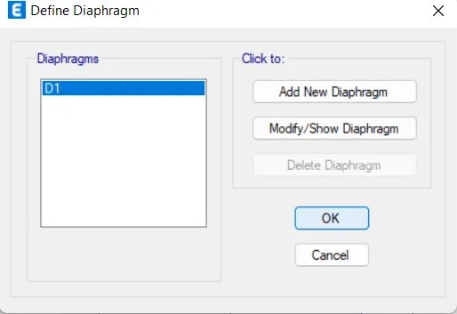
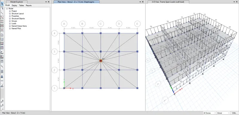
- Now we have crearte the diaphgram to the srtucture.
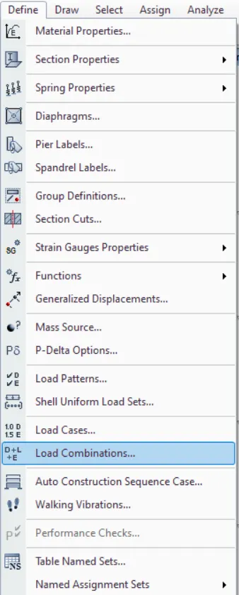
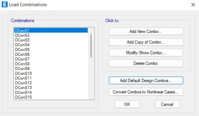
- After that we need to define the load combinations.For this Go to define tab-load combination.and select the concrete frame design select and click ok.
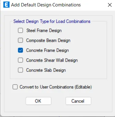
- Then it will generate the auomatic load combinations as per the codal provision.
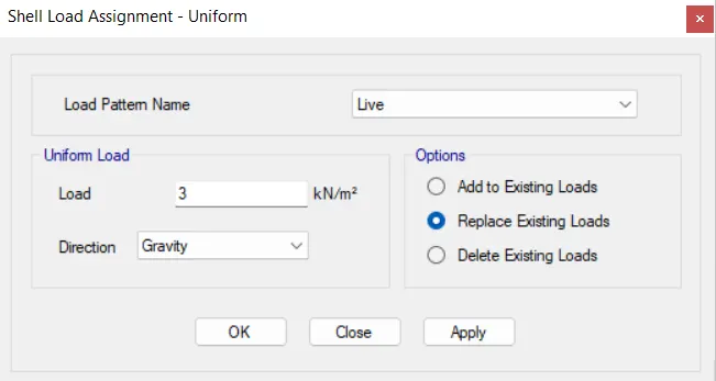
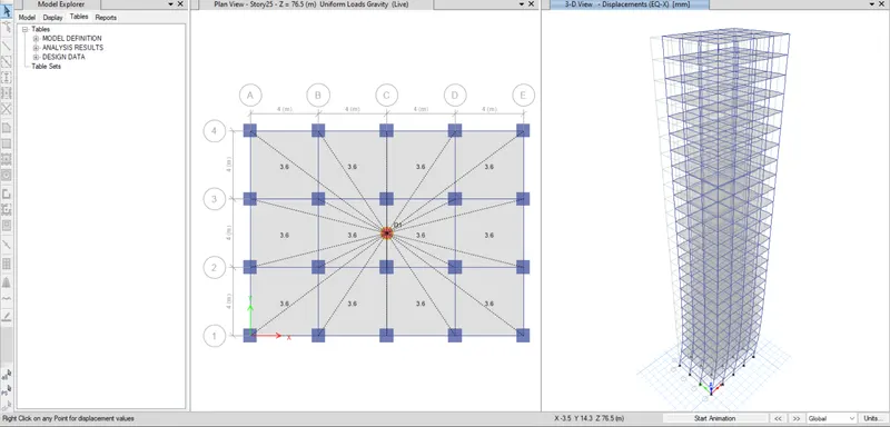
- Now select the all floors by go to the select tab-select-object type-Floors -ok. then all floors are slected.
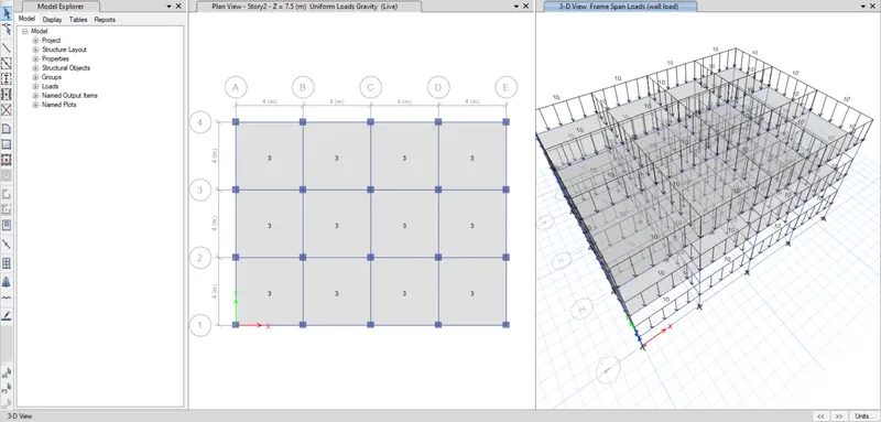
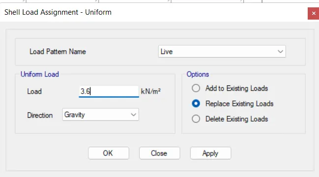
- Then go to the assign tab-shell lods- uniform-live load-3-apply-ok.
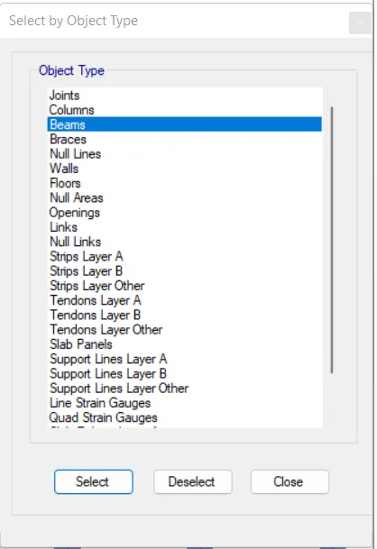
- Now select the all beams by go to the select tab-select-object type-beams -ok. then all beams are slected.
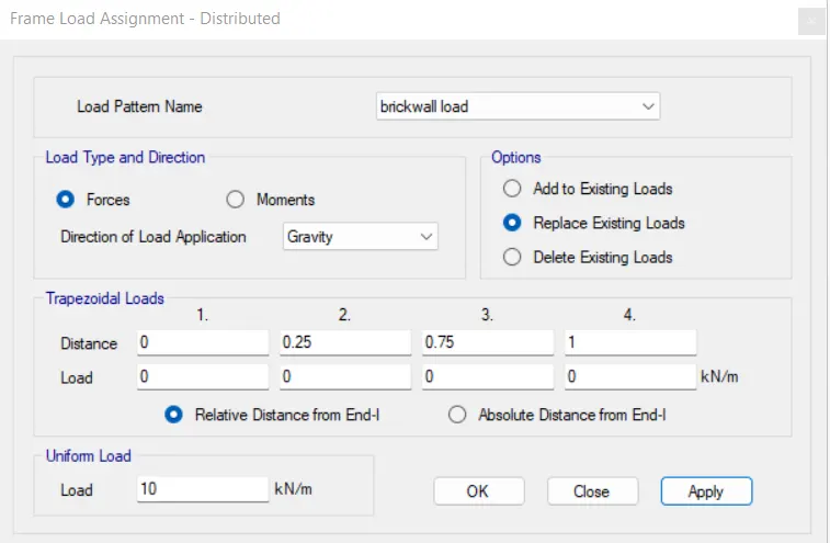
- Then go to assigntab- frame loads- Distributed -load pattern-brick wall load-load-10-apply ok.
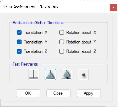
- We have to keep the supports as pinned, so we have sleect the all joints in base storey.Then go to assign-joints-restraint-select pinned joint.
- Finally go to the analyse tab-check model- It is checked for any errors and warnings.


- Now the model is ready for the analyse.so we can run analysis.
- Hence run anaylsis has been completed.
Hence the file saved as BuildingA- 2 storey building.
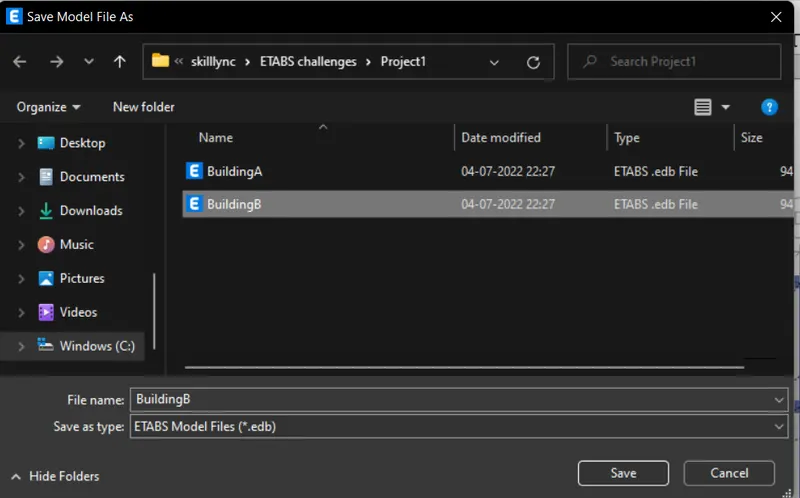
- Now save as the previous modal as building-B. for building A and B are same all propeties and all.where the difference in only no.of stories.
- Now go to the edit tab-edit stories and grid sytems and add 3 stories and change to the similar of storey-1.
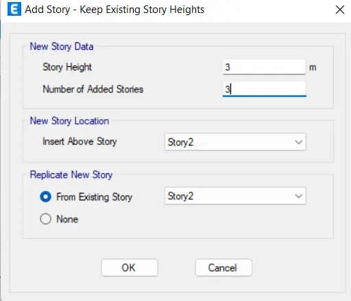
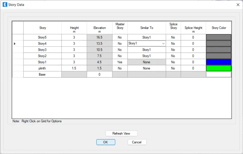
- Now make sure that all propoerties are assign to the remaining stories.
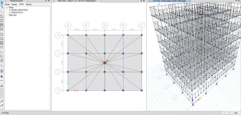
- Then analyse the model
Hence the file has been saved as BuildingB-Bench mark 5 story building.
- Now by using the save as option save the bilding B to building C.In this model have a changes on the columns dimesions respectively and the column orientaion is in x axis.
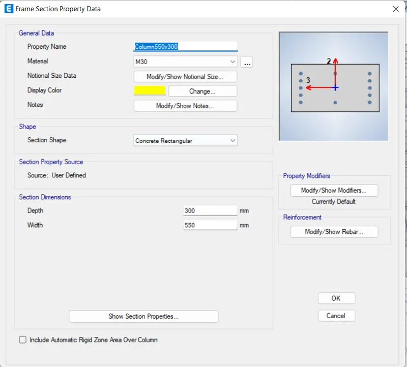
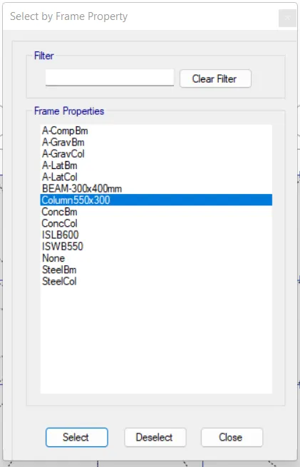
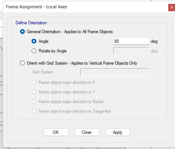
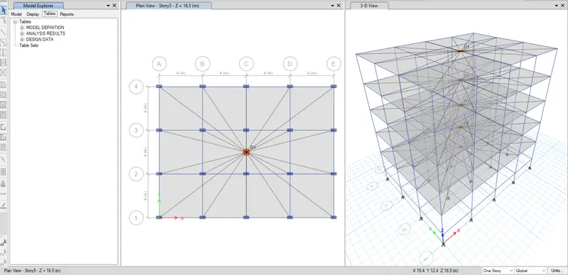
Now save the file as Building C-5 storey model where the column orientation is X axis.
- now by using the save as option save the Building C to D. where compare to the both models In modal D the The column oreintation is y axis.And all properties are same as the modal C.
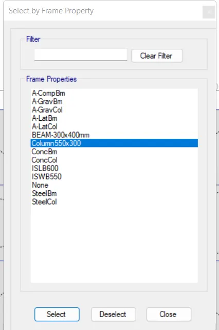
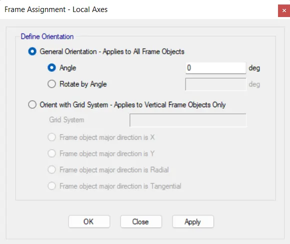
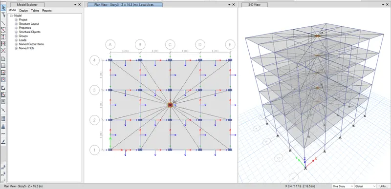
- Then it is ready for the run analysis and it is done.
Hence the file is saved As the Building D-5storey building which the columns are orientated In the Y direction.
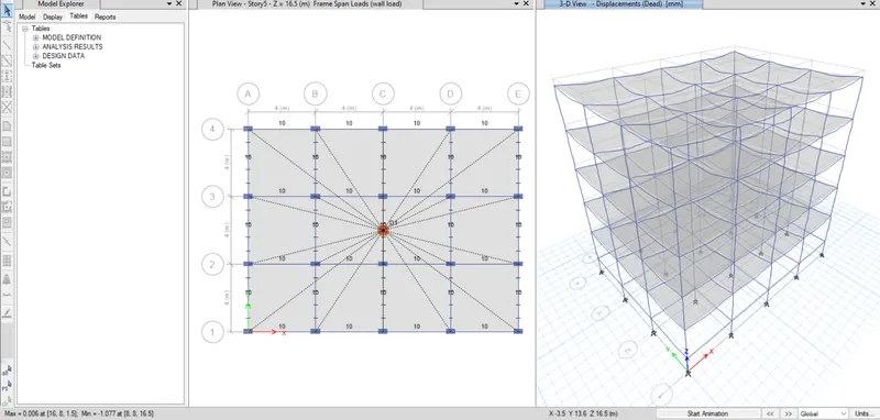
- Now by using the save as option save the Modal D to Modal E.in the model E their is an extra 5 storeys are added.And thier is also change is in the columns dimensions.bottom 5 storeys is of columns-600x600. and upper 5 storeys columns are 400x400.
- Go to edit tab and add the stories.
- Change the column dimensions. also as per the question given.
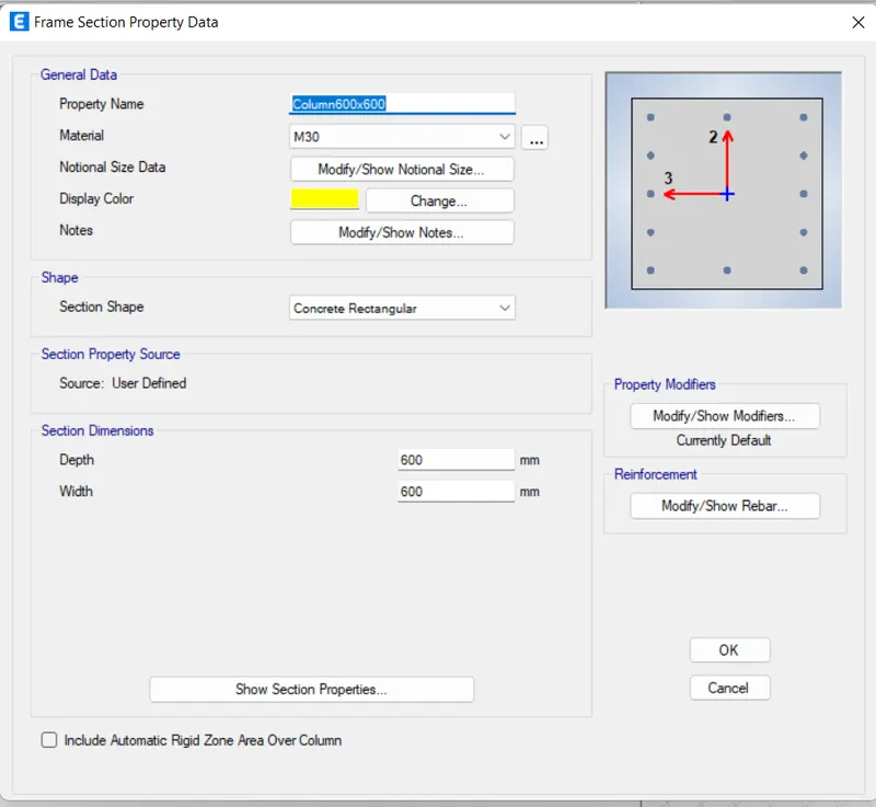
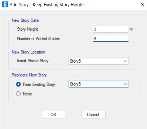
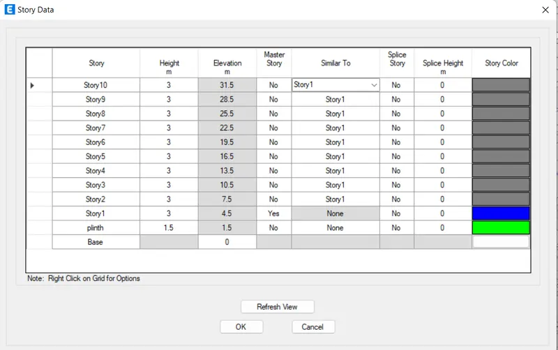
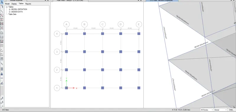
- Now its ready for run analyze. and save it model-E
Hence the file is saved as BuildingE-10 storey building With two diffrent types of columns.
Similarly Hence the file is saved as BuildingF-10 storey building With one types of columns.
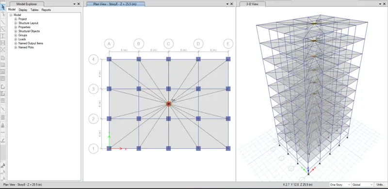
Similarly Hence the file is saved as BuildingG-25 storey building With three types of columns.
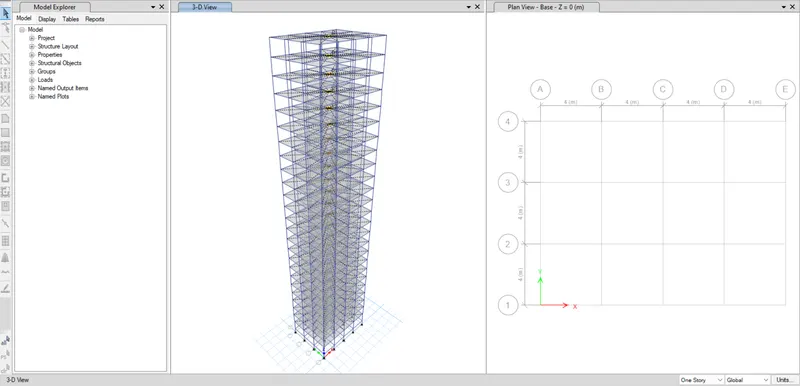
Similarly Hence the file is saved as BuildingH-25 storey building With one types of columns.
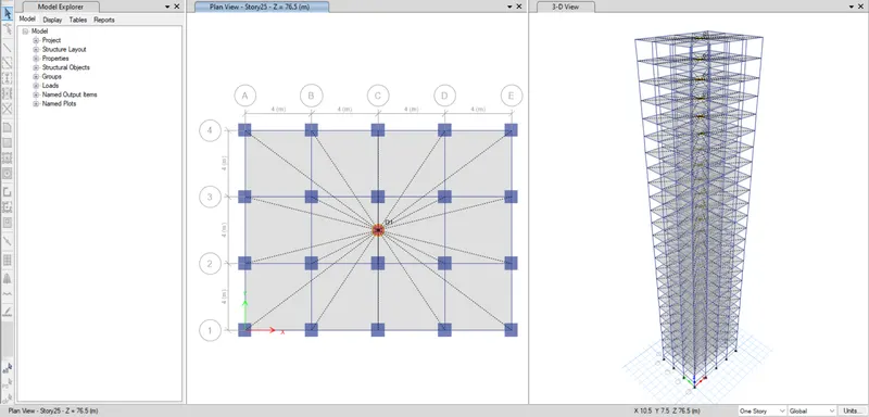
Similarly Hence the file is saved as BuildingJ-25 storey building With one types of columns and increasing the 10% in imposed load.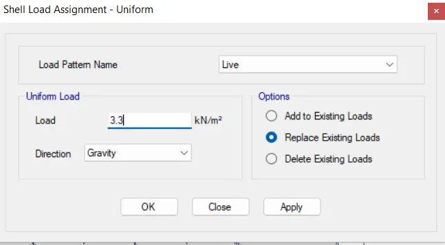
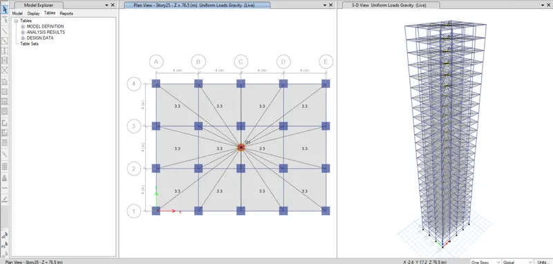
Similarly Hence the file is saved as BuildingK-25 storey building With one types of columns and increasing the 20% in imposed load.
RESULT:
We study and anayalse for all the buildings where types A to K.given below cases are studied for only mode1 of each buildings.
And we compare the Fundamental modes shapes and natural time period for each type of buildings.
TABLES FOR MODALPERIOD AND FREQUENCIES FOR ALL TYPES OF BUILDINGS ARE SHOWN IN BELOW:
BUILDING-A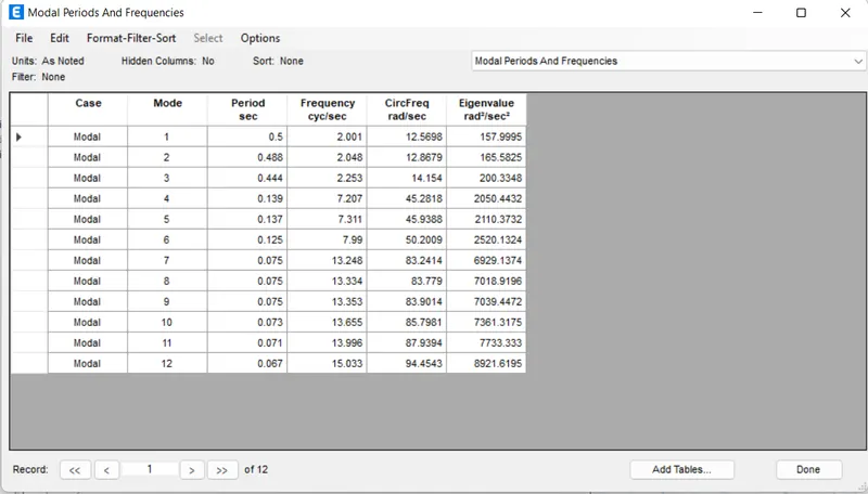
BUILDING-B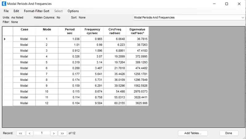
BUILDING-C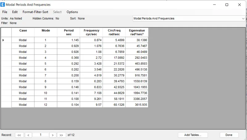
BUILDING-D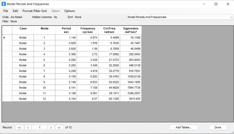
BUILDING-E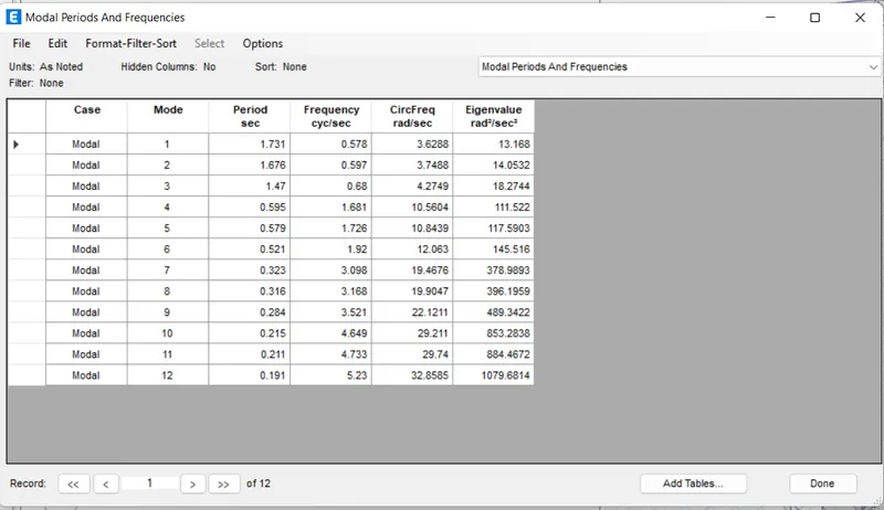
BUILDING-F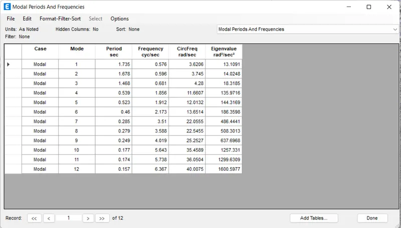
BUILDING-G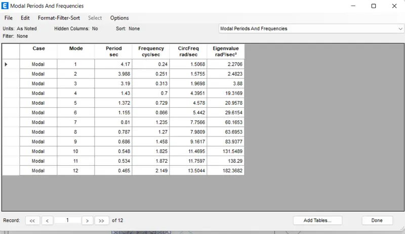
BUILDING-H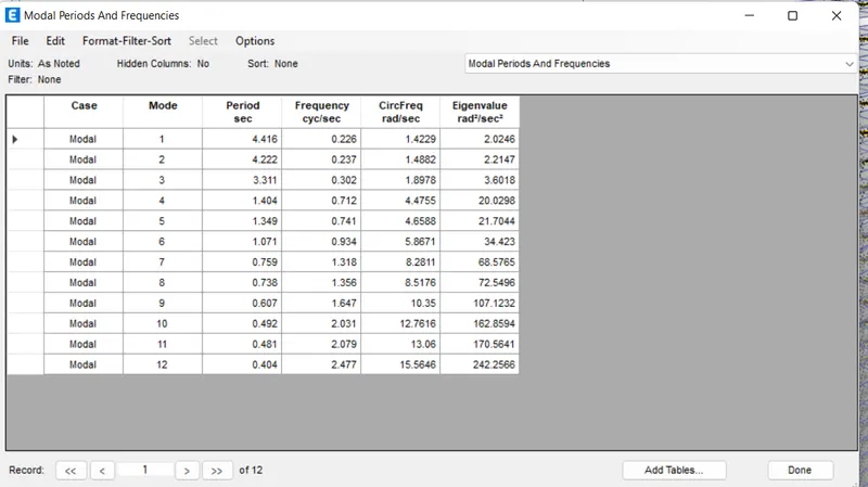
BUILDING-J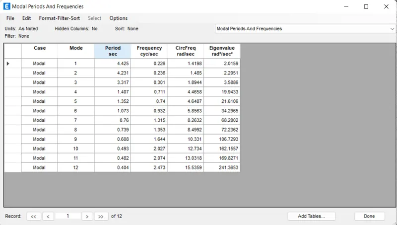
BUILDING-K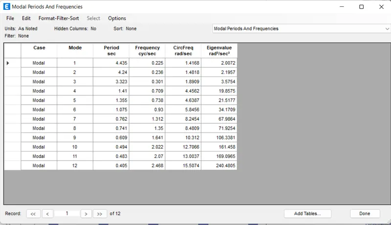
1.Comparsion of effective stiffness on time period.
- Between model E and F
model-e time period=1.73s
model-F time period=1.73s
when comparsion between the model E and F there is no change in Effective stiffnes on time period. - Between model G and H.
Model-G time period=4.17s
Model-H Time period=4.41s
When comparsion of both the models model G is more stable then the Model H of effective stiffness on time period.
2.Comparsion of Effective mass on time period.
- Between the models H, J and K.
MOdel-H Time period=4.41s
MOdel-J Time period=4.42s
MOdel-K Time period=4.43s
When comparing the three models .we also knnow that mass is directly proportional to the lateral displcemnet.so if the mass is increases the lateral displacement is also respectively increases.
3.effect of building height in time period.
- Between the models A,B,F and H.
MOdel-A Time period=0.5s
MOdel-B Time period=1.036s
MOdel-F Time period=1.73s
MOdel-H Time period=4.41s
When comparative of above four models. we can easily say that if the height of the model increases respectively time period also increases,beacuse the Height of the building is directly proportional to Time period.
4.Effective column orientation of time period.
- Between the models B,C and D.
MOdel-B Time period=1.036s
MOdel-C Time period=1.14s
MOdel-D Time period=1.12s
When comparasion of three models.The model B taks place the less defelection and lateral load case. now coming to the model C It will deflect in x-direection due to the column orientaion in X-axis,and coming to the MOdel D it will deflect in the Y-direction due to the column orientaion in Y-axis.
5.Effect of flexural stiffness of structural elements on mode shapes:
- between the B regular building and the to its changing the zero interia of the Building B.
Model-B-Zero interia Time period:2.62s
MOdel-B Time period=1.036s
When comparative of two models.If we dont consider the stiffness then the time period will increases it effects on the model.So we are Consider the Flexural Stiffness.
6.Effect of axial stiffness of vertical memebers on mode shapes.
- taking the same model H and anither changing tha axial as zero for model H.
MOdel-H zero Axial- Time period=5.99s
Model-H regular time period=4.41s
When comparative of two models.If we dont consider the Axial stiffness then the time period will increases it effects on the model.So we are Consider the Axial Stiffness.
7.Effect of degree of fixity at column base on mode shape.
- Betwewn the Model B and changing the model B supports to the fixed one.
MOdel-B Time period=1.036s
MOdel-B Fixed end -Time period=0.941
When comparsion of two models.definetly the degree of fixity of column shows effects on the mode shapes.IN this case the fixed end base gives more stable.
REPORT:
| criteria | Models | analysis Result | Conclusion |
| 1.Comparsion of effective stiffness on time period. | E | 1.73S |
|
| F | 1.73S | ||
| G | 4.17S | ||
| H | 4.41S | ||
| 2.Comparsion of Effective mass on time period. | H | 4.41S |
|
| J | 4.42S | ||
| K | 4.43S | ||
| 3.effect of building height in time period | A | 0.5S |
|
| B | 1.03S | ||
| F | 1.73S | ||
| H | 4.41S | ||
| 4.Effective column orientation of time period. | B | 1.03S |
|
| C | 1.14S | ||
| D | 1.12S | ||
| 5.Effect of flexural stiffness of structural elements on mode shapes: | B-ZERO INTERIA | 2.62S |
|
| B | 1.03S | ||
| 6.Effect of axial stiffness of vertical memebers on mode shapes. | H-ZERO AXIAL | 5.99S |
|
| H | 4.41S | ||
| 7.Effect of degree of fixity at column base on mode shape. | B | 1.03S |
|
| B-FIXED ENDS | 0.941S |