Project 1_Comparative study of different storey buildings for Seismic forces
Project - 1
Etabs
Question no.1:
Factors influencing the dynamic characteristics of a building
Factors influencing the Natural Period of a building
Factors influencing the Mode shape of oscillations
- Aim:
- To create structural models of various specification using ETABS software.
- To follow suggested specification
- Analys the structural models using ETABS software
- Procedure:
- Initially open the ETABS software.
- Then create new model file by clicking the new model tab in the software opening interface.
- After the this save the model with appropriate names.
- In this project we are going to model 10 structural models , each consisting different specifications.
- Specification change such as column size, column alignment and the no.of story in the model.
- Initially let us start the model with model A.
- MODEL A:
- In model A, we are suggested to create 2 story buidling with said column and beam sizes.
- So to creat the model.
- Open the new model and save the model as Model A.
- Now first of all we need to set the story and grid data to place the beams, column and slabs in the model.
- So go to edit setting in the tool bar and open edit story and grid settings.
- In that change the setting to customize grid and stroy data.
- First let us customize the grids which is going to be permanent grid setting throughout the model.
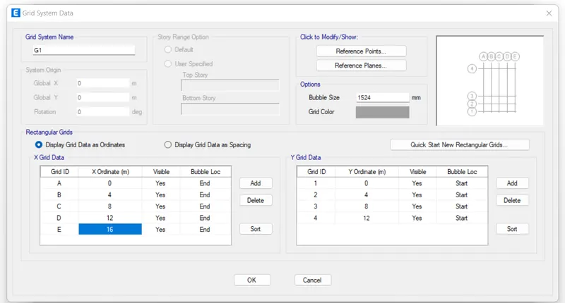
- As suggested we need 5 grids in the X direction adn 4 grids in the Y direction.
- The grid distance to be set in 4m between all grids.
- Thus created grid data is shown below
- After the creation of the grid data we need to edit teh story data.
- No choosing the edit story option.
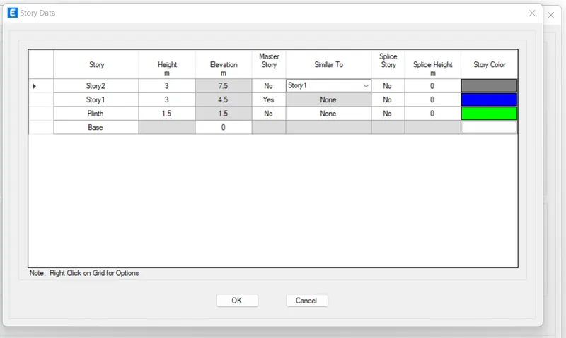
- We need to creat 2 story excluding plinth and base.
- The story distance here we are setting as 3m between each story as standard story heights.
- To add story we need to right click on the arrow mark on the left side of the last story and edit the additional story settings.
- After adding the story to the existing story data.
- We need to make the story1 as master story not the plinth or base.
- As the remaining story to be marked as the similar story to story 1
- Thus created story data is shown below
- Thus the story and the grid datas for the modelA is set up.
- Now we need to define the material properties of the components to be used in the model.
- To define the material prperties of the components we need to define the material to be used.
- So, go to the define option on teh tool bar.
- And in the define option choose material properties.
- In material properties create a new material by clicking add new material.
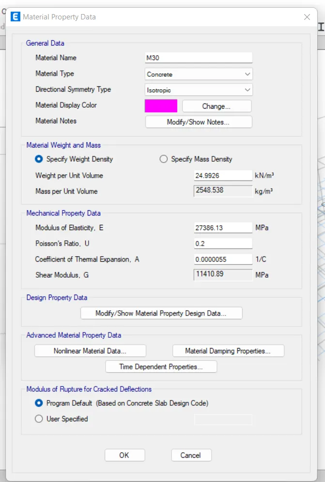
- Now we need to create concrete material, in this whole project we are going to use M30 grade concrete as teh standard concrete grade.
- hence setting the grade as M30., and checking all other parameter of the concrete we can the add teh created material property.
- Thus created concreted concrete property is shown below.
- Now after this we need to create a material for reinforcement.
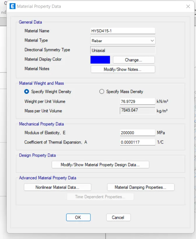
- In this project we are going to use rebar as HYSD415(Fe415) for the steel.
- Hence add new property for the steel.
- Thus added rebar property is shown below
- In this whole project we are going to use the above created material properties as the standard property for all the models to be created.
- Hence the material property was created.
- Now let us create the modeling elements like , beams, column and slab.
- The size of the column, beam and slab varies with each model.
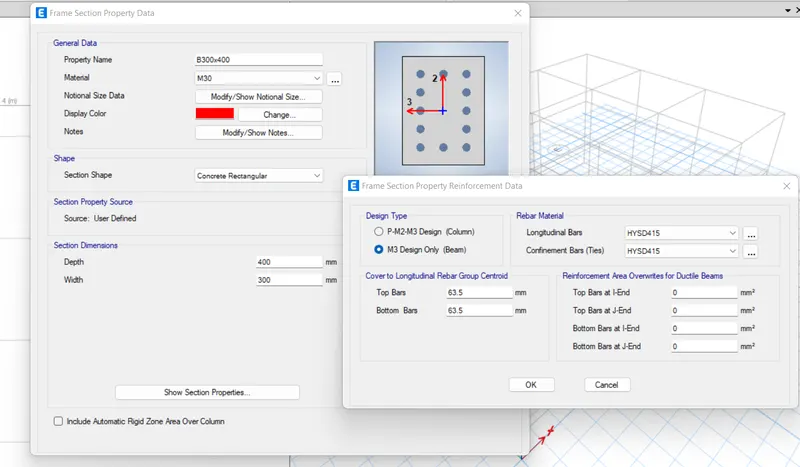
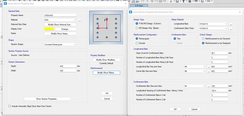
- For the model A we are goin to create column size as 400x400mm, Beam as 300x400mm and slab thickness as 150mm.
- Initialy creating the beam.
- To create the sections go to the define option in the tool bar.
- And then selet section properties.
- In section properties we need to add the required section.
- First is beam so seelct the concrete rectangular section.
- And then add the sizes and add the material type in teh sections.
- Thus the beam is created.
- After the beams create the column section.
- By adding the new section property as concrete section.
- And setting up teh required column size for the model A.
- And adding the required material for the section.
- Thus the column is created.
- After the column creation we need to create a salb section.
- To create slab section we need seclect define option as did before and section properties in that slab sections.
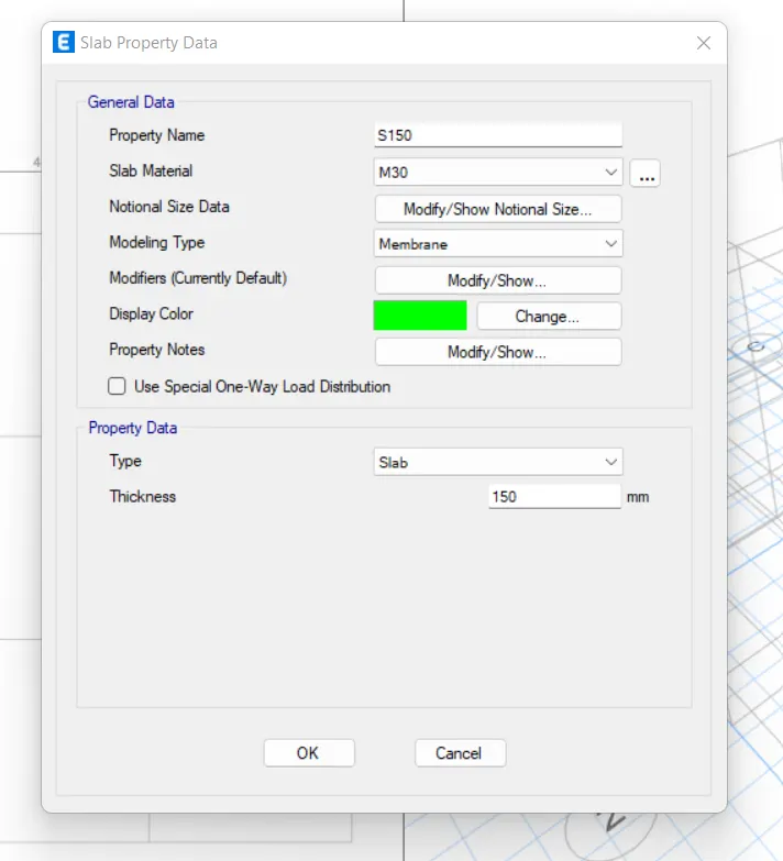
- And selecting slab section we need to add property and name the section as S150 and edit the section property
- And provide modeling type as membrane.
- then input the required slab thickness.
- Thus the slab is created.
- The created slab is to be used in all the models in this project.
- After the slab creation we need to define the load patterns to be used in the model.
- The creating load patterns will be used in the rest of the models in the project.
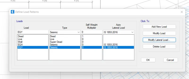
- Add wall load, EQX and EQY.
- Other loads like Live load and Dead loads preexists in the software o we can add according to our requirement.
- EQX and EQY are assumed to be seismic loads and the load pattern reference is set to IS1893:2016.
- thus created load pattern is shown below
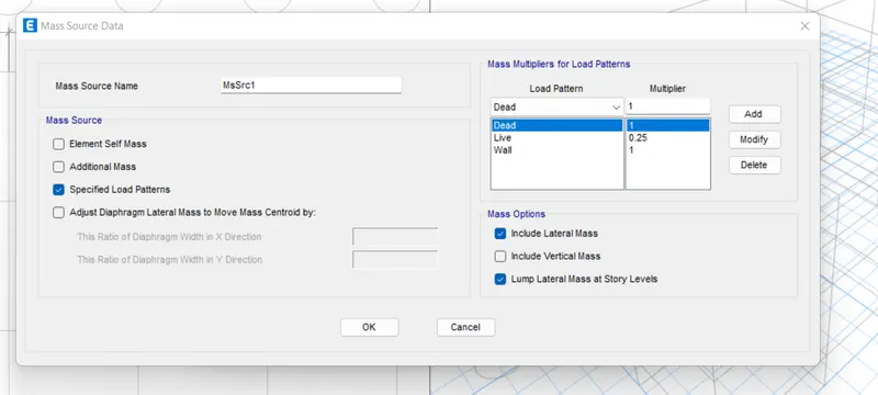
- After setting up teh lload pattern we need to set up mass source.
- In mass source we are setting up load multplier of the load pattern created.
- Thus created mass source is shown below.
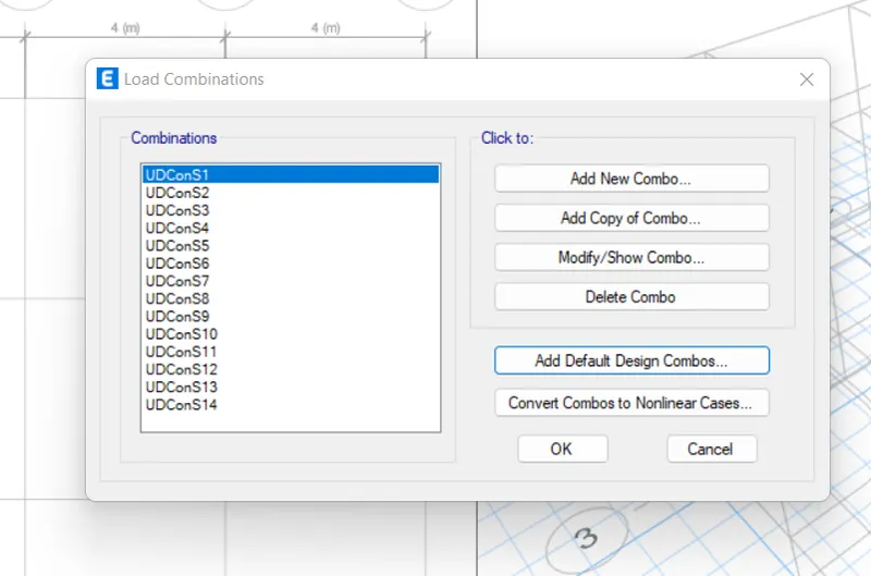
- Then the load combination is set up.
- Hence the pre modelling settings are done and teh modelling of teh structural model can be stared.
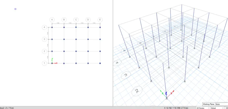
- Now the model is started by placing the elemens.
- Column sections are placed on the required grid points.
- And the beams are placed on the grid lines .
- Both the columns and beams are placed by using quick draw tool.
- Thus the placed model is shown below.
 \
\
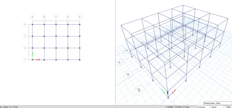
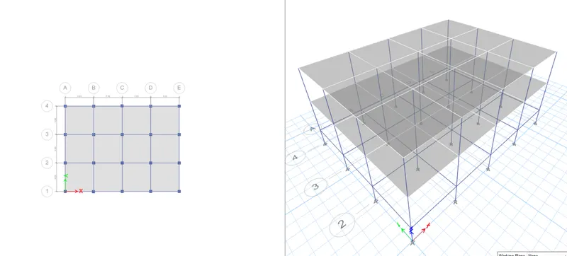
- And then teh slab is placed by the same quick draw method.
- Thus the slab created is shown below.
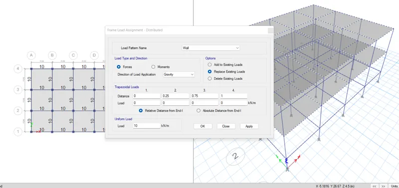
- Then the created load is assigned in the model to the beams.
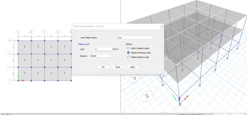
- To the slabs
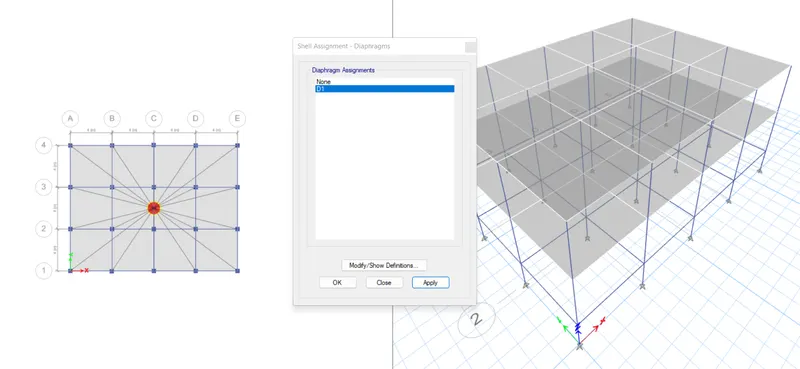
- After the laod is being assigned we are assigning diaphragm to the slab
- Hence the model is created and the analysis of the structure is done.
- MODEL B:
- The modal B has the most of teh specification of the modal A.
- Hence the model is created as of the modal A.
- But in this model we are going to change the storey height and do teh analysis.
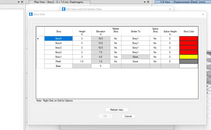
- Here we are increasing the story to 5 storey.
- Hence following the story edit settings as of model A the created story is shown below.
- And then with same loads and settings the analysis is run for the model B.
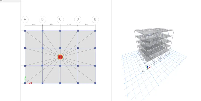
- The run analysis is shown below
- MODEL C:
- Following most of the specification as of the models created before.
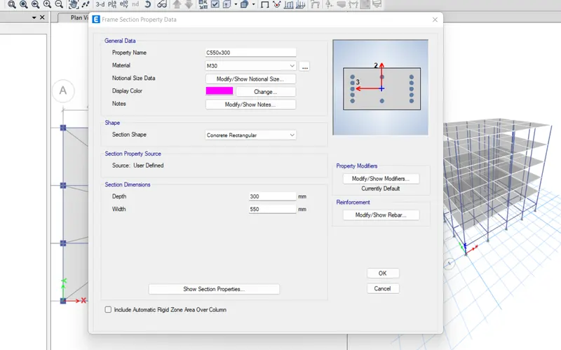
- Here we are changin the dimensions of the columns.
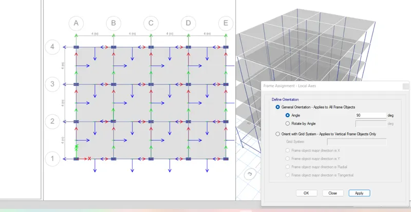
- And then, as the created column dimension creates the column as rectangular column so changing the axes of the columns as required.
- Thus changed column sizes and axes are shown below.
- The axes change is 90 degrees
- Then following specification of previous models.
- With changed specifications in the model the analysis was run
- Thus the analysis is shown below.
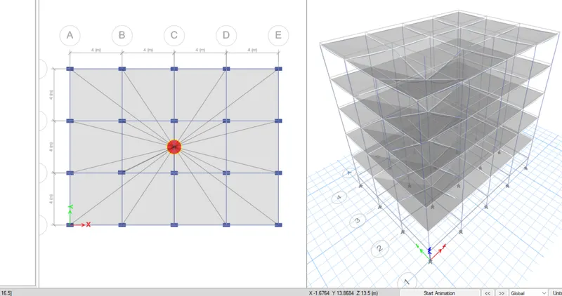
- MODEL D:
- In this model we are just going to change axes of the columns created from the model before.
- In the previous model we changed the axes of the columns to 90degrees.
- And in this model we are making the axes of teh column back to 0 degrees.
- Thus the changed axes is shown below
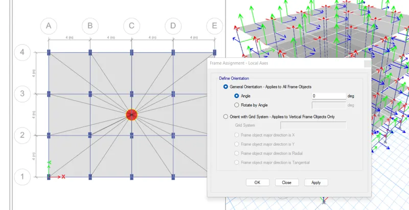
- Then as like previous models diaphragm for the slabs is set and the analysis was run.
- Model E:
- In this model we are going to do certain changes like change in column size and story.
- So following the method of changing teh story numbers we are changing the story of the building to 10 story.
- And make the stories similar to story 1 as did before.
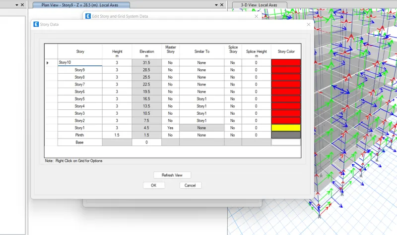
- After this process we are adding the new column size required for the mdol.
- We are going to create newly 600x600 column size where 400x400 is the column size we are currently using.
- Here bottom 5 stories are going to have 600x600 column sizes.
- And the remaining top stories are going to have 400x400 size columns.
- So teh column size of 600x600 is created.
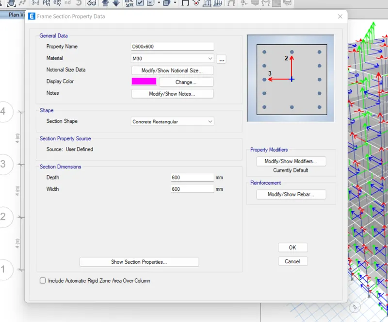
- So now we are going to place the column size in the model.
- For that , as there is 400x400 column present in all teh stories we need to change the column size only is the bottom 5 stories columns.
- For that we need to go to the view tab.
- And edit the visibilty of the story setting to bottom stroey to 5th story.
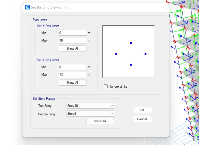
- And then in the viewelemets tab we need to offf the beam and slabs.
- And then select teh bottom 5 story.
- And then columns gets selected.
- now we need to set teh new column section with dimension 600x600.
- Now after the chane we can see teh chjange in teh column names.
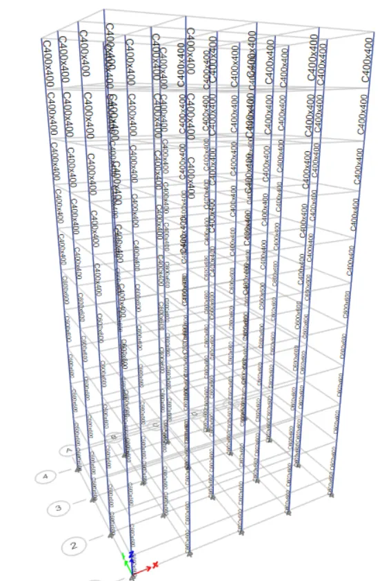
- Now teh vissbility setting are reset.
- And teh by the same way we need to set teh diaphragm.
- And continue to analysis.
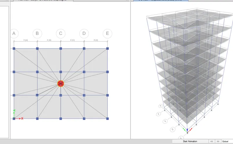
- MODEL F:
- In thsi model we are doing some changes.
- The story of the building is increased.
- Additional 15 stories are added to teh model.
- By following the same method followed in the previous models.
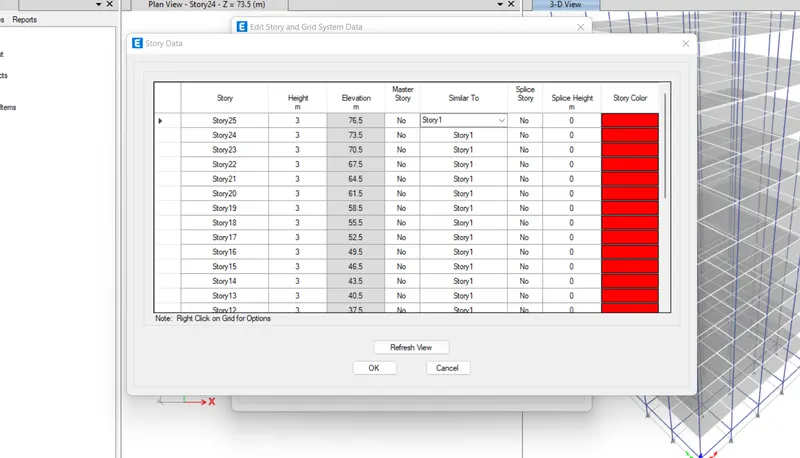
- Now all the column sizes in the entire model is changed.
- The dimension of teh column is changed to 600x600.
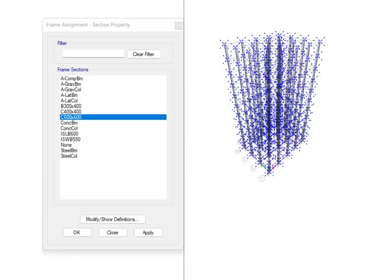
- And teh by the same way we are running teh analysis for teh altered model.
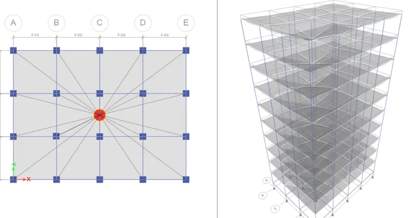
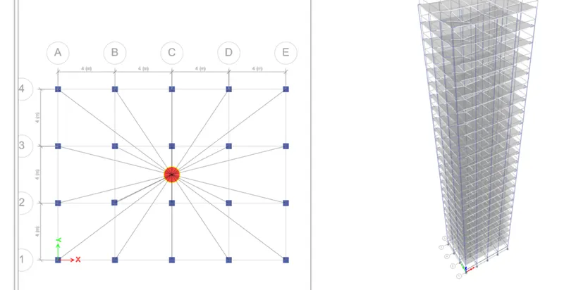
- MODEL G:
- In this model G we are doing a change.
- By addidng different column sizes alonhg the stories
- Additionally 800x800 columns are added to teh model.
- Bottom 10 stories are set with 800x800 column size.
- And from 11 to 20 we are adding 600x600 section columns.
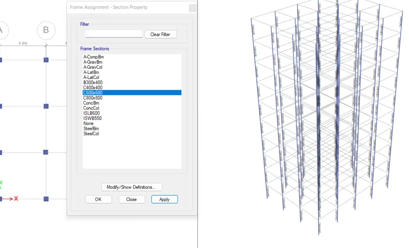
- And then for teh last stories 20 to 25 we are adding 400x400 columns.
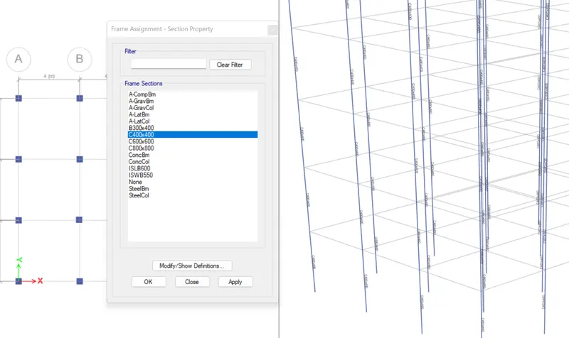
- After the changes being done.
- The analysis process is takes as like the previous models.
- Thus the analysis image is shown below.
- MODEL H:
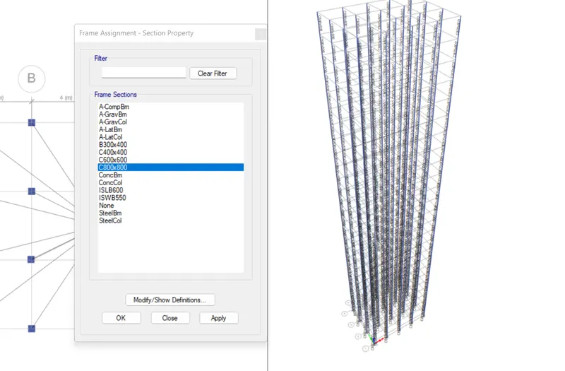
- In this model the change is going to be less.
- Here we are going to change the column dimension to all teh story.
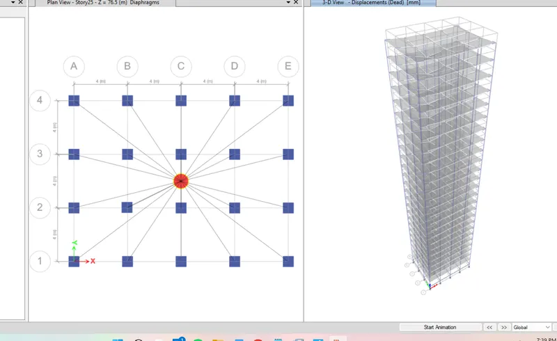
- The model's complete columns are changed to 800x800
- After this the model is set for analysis
- MODEL I:
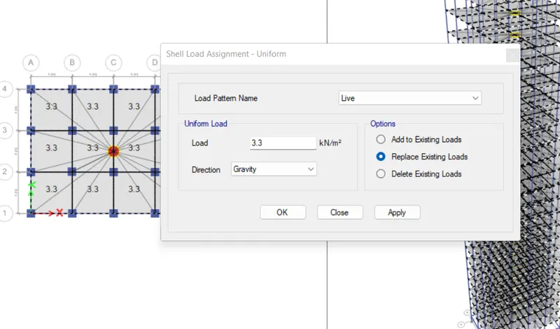
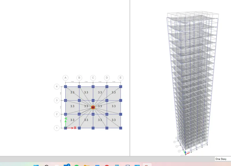
- In this model we are just going to add 10% of the existing imposed load.
- That we created for the model A and followed for the models till Model H.
- 3KN/m^2 was our existing load adn increased to 3.3 KN/m^2.
- And following all the other specifications of the model.
- the analysis is done.
- MODEL J:
- This model is same as Model I.
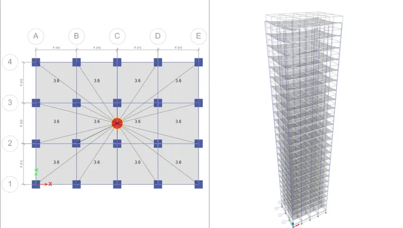
- the change is going to be increament of load to 20%.
- Thus 3.3Kn/m^2 is changed to 3.6KN/m^2.
- And teh remainaing specification is going to be the same.
- And teh analysis is done.
- Final Analysis results of the model:
- Criteria:
- Effect of stiffness on time period for Building E (10 Story with varying column size) : 1.81 s
- Effect of stiffness on time period for Building F (10 Story with uniform column size) : 1.81 s
- Effect of stiffness on time period for Building G (25 Story with varying column size) : 4.17s
- Effect of stiffness on time period for Building H (25 Story with uniform column size) : 4.41s
- Effect of mass on time period for Building H (25 Story with 3KN/m^2 imposed load) : 4.41s
- Effect of mass on time period for Building I (25 Story with 3.3KN/m^2 imposed load) : 4.42s
- Effect of mass on time period for Building J(25 Story with 3.6KN/m^2 imposed load) : 4.43s
- Effect of column orientation on time period for Building B (All floors column size 400x400) : 1.03s
- Effect of column orientation on time period for Building C (All floors column size 550x300 in X direction orientation) : 1.14s
- Effect of column orientation on time period for Building D (All floors column size 300x550 in Y direction orientation) : 1.12s
- Effect of flexural stiffness of structural elements on mode shape for Building B (Flexural stiffness of beams close to 0(Zero inertia) : 2.62s
- Effect of flexural stiffness of structural elements on mode shape for Building B (Flexural stiffness of beams(Regular) : 1.03s
- Effect of Axial stiffness of vertical members on mode shape for Building H (Axial cross section for columns is close to 0(Zero axial area) : 5.99s
- Effect of Axial stiffness of vertical members on mode shape for Building H (Axial cross section for columns(Regular) : 4.41s
- Effect of degree of fixity at column base on mode shape Building B (column support pinned(Regular) : 1.03s
- Effect of degree of fixity at column base on mode shape Building B (column support fixed : 0.941s
- Result:
- The model was created.
- Suggested paramters and specifications were used.
- Analysis was run on the model using the Etabs
- And the results from the analysis was updated