Project 1_Comparative study of different storey buildings for Seismic forces
Project - 1:
Comparative study of different storey building for seismic forces:
Ans:
Procedure for modeling of building for Analysis and design in E-Tabs software:
1. Model Initialization:
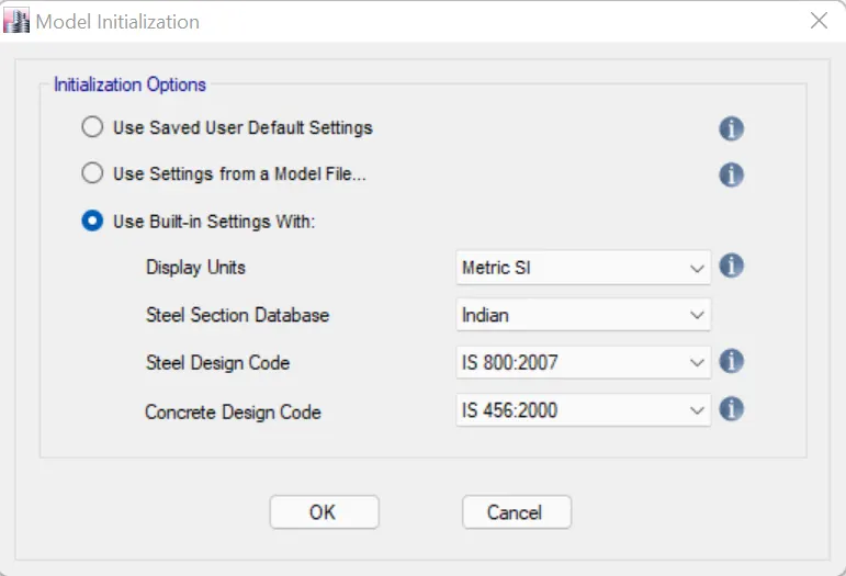
- Open ETABS software.
- Click "File" -> "New Model".
- In the "Model Initialization" window, set units (e.g., meters, feet) and analysis options (2D or 3D).
2. Define Grid System:
- Go to "Define" -> "Model" -> "Grid Data".
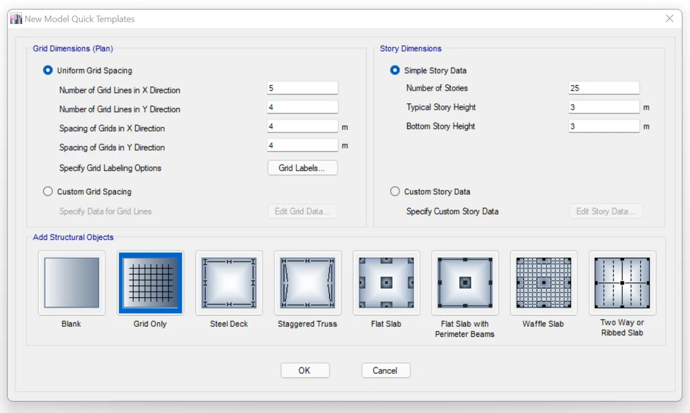
- Choose "Custom Grid Spacing" and click "Edit Grid Data".
- Define the grid layout for the building footprint. This includes the number of bays in each direction and spacing between grids.
3. Define Story Data:
- Go to "Define" -> "Model" -> "Story Data".
- Choose "Custom Story Data" and click "Edit Story Data".
- Define the story heights for all 25 floors. You can set a master story height and specify variations for other floors.
4. Define Materials:
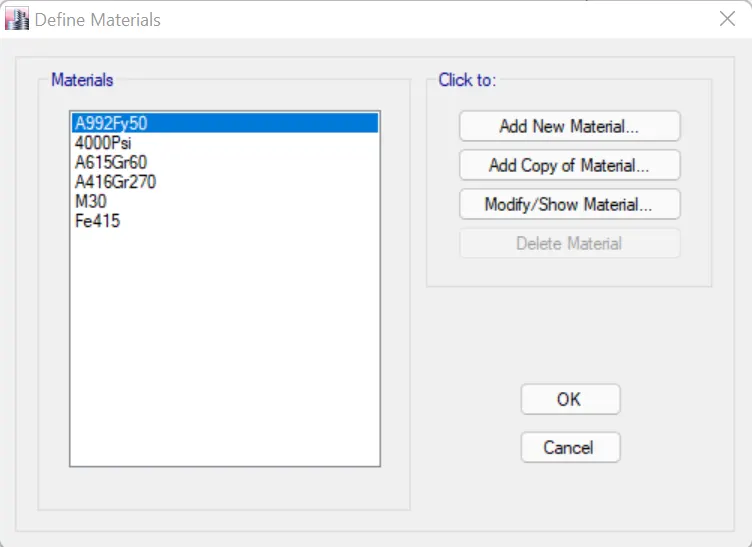
- Go to "Define" -> "Materials".
- Click "Add New Property".
- Specify material properties like concrete or steel, including density, strength, and Poisson's ratio. You can define separate materials for different structural elements (columns, beams, slabs).
5. Define Sections:
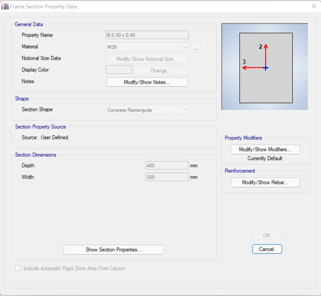
- Go to "Define" -> "Section Properties".
- Choose the element type (e.g., beam, column, slab).
- Click "Add New Property" and define the section geometry. This includes dimensions like width, depth, and thickness for beams and columns, or slab thickness.
6. Model Geometry:
- Use the "Draw" menu to create beams, columns, and slabs.
- Columns: You can use quick draw options or define them by coordinates.
- Beams: Similar to columns, use quick draw or define by connecting grid points.
- Slabs: Define the slab area by selecting the building footprint.
7. Assign Properties:
- Select the beams, columns, and slabs you created.
- In the "Properties" window, assign the corresponding material and section properties defined earlier.
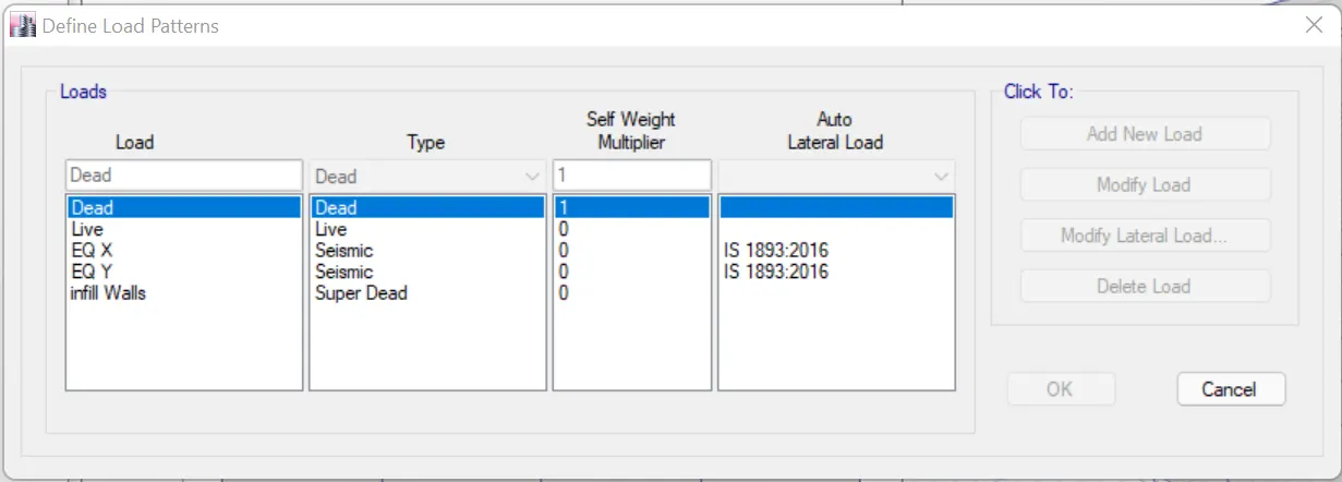
8. Define Loads:
- Go to "Define" -> "Load Patterns".
- Define load patterns for different types of loads (e.g., dead load, live load, wind load, earthquake load). You can specify the load value or use pressure per unit area.
9. Define Load Cases and Combinations:
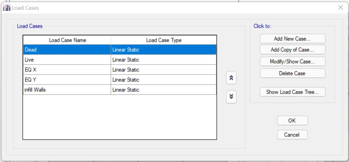
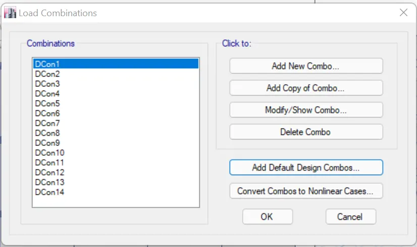
- Go to "Define" -> "Load Cases".
- Create load cases by combining different load patterns (e.g., dead load + live load, all seismic load cases).
10. Analysis and Design:
- Once the model is complete, you can proceed with structural analysis in ETABS.
- The software can calculate internal forces, deflections, and assess member capacity based on the defined materials, sections, and loads.
[Note: this is the procedure for different types of buildings in E-Tabs software.]
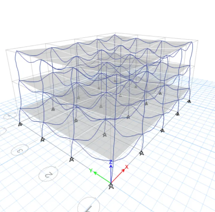
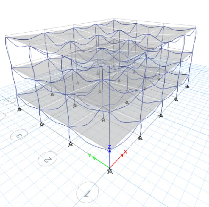
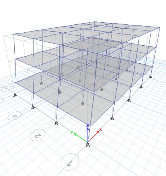
Building - A: (G+2 Building)
Step-1: Open E-Tabs Software and click on New Model
Step-2: change Units and Design standards for model and click ok
Step-3: Change model spacings, Dimensions, storey details and gird model click ok
Step-4: create material properties concrete as M30, and Steel as Fe415.
Step-5: Create Section properties as (Beam - 300x 400), (Column - 400 x 400), and (Slab thickness as 150mm).
Step-6: Assign all properties to the frame model.
Step-7: Create Load patterns Dead load, Live load, Earthquake load in X and Y directions,and infill wall loads.
Step-8: Create Load combinations also.
Step-9: Assign all Loads to the frame model
Step-10: check the frame model and Analyze the frame model.
Result:
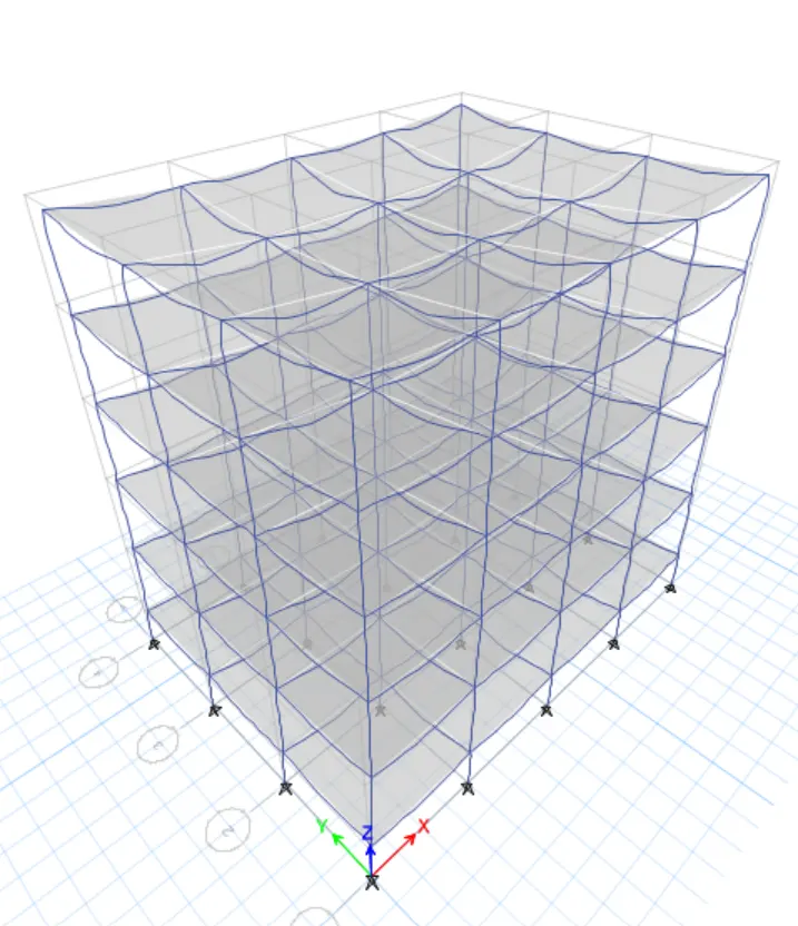
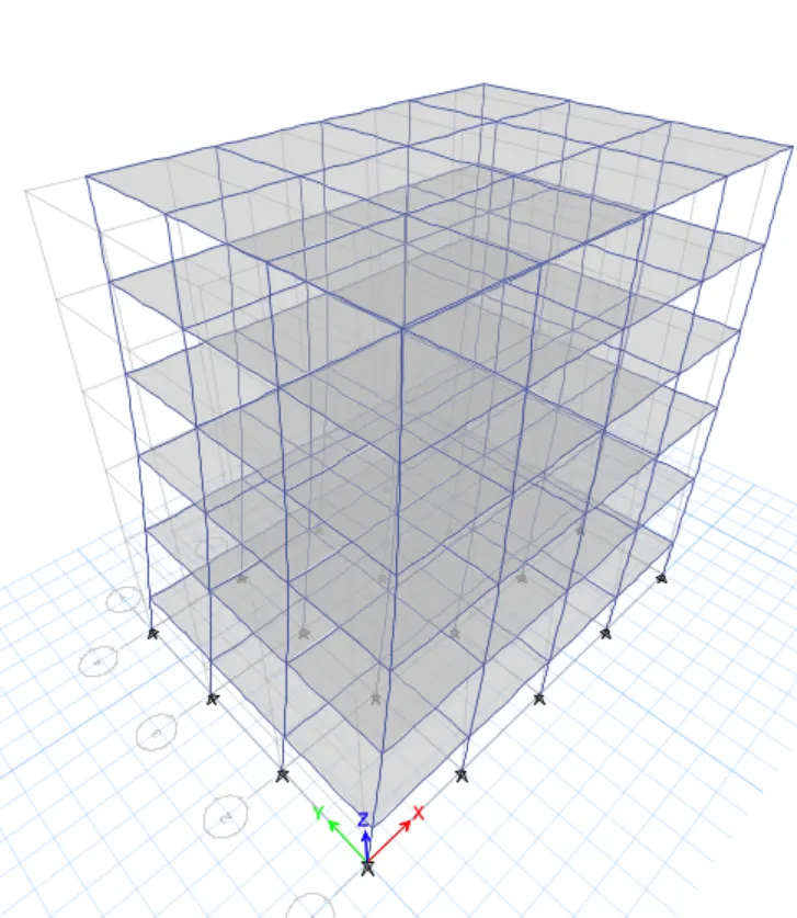
Building - B: (Benchmark 5-storey building)
Step-1: First of all copy the pervious G+1 Building work file and paste in another folder
Step-2: Open copied file
Step-3: click on Edit icon and select Edit stories and grid systems
Step-4: Click on Modiy /show storey data
Step-5: Right click on upper storey (Storey 2 in this file)
Step-6: click on Add storeyin that click on keep existing storey heights
Step-7: Give storey height and number of added stories click ok.
Result:
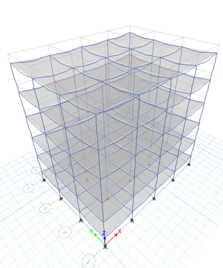
Building - C: (Benchmark building with rectangular columns oriented along x direction)
Step-1: First of all copy the pervious G+4 Building work file and paste in another folder
Step-2: Open copied file
Step-3: click on Define and select Section properties than select frame section
Step-4: Double click on Column section
Step-5: Edit column sizes to 550 x 300
Step-6: Click ok and assign the updated property to the model.
Result:
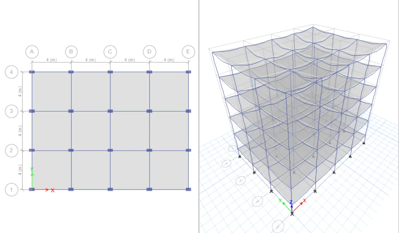
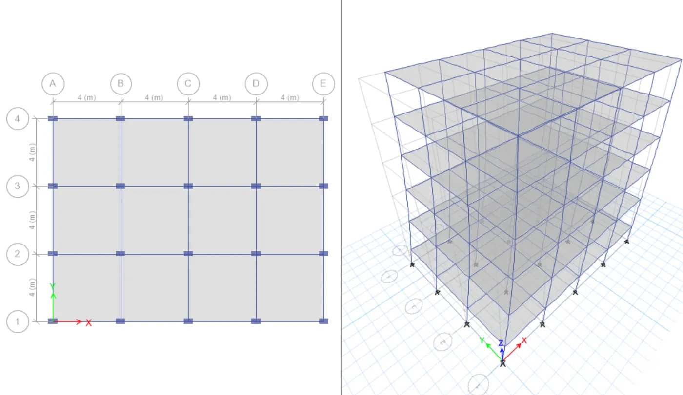
Building - D: (Benchmark building with rectangular columns oriented along Y direction)
Step-1: First of all copy the pervious G+4 Building work file and paste in another folder
Step-2: Open copied file
Step-3: click on Define and select Section properties than select frame section
Step-4: Double click on Column section
Step-5: Edit column sizes to 550 x 300 in Y direction orientation
Step-6: Click ok and assign the updated property to the model
Result:
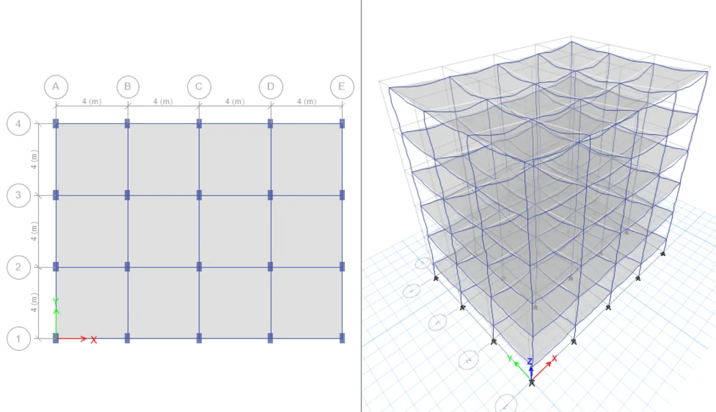
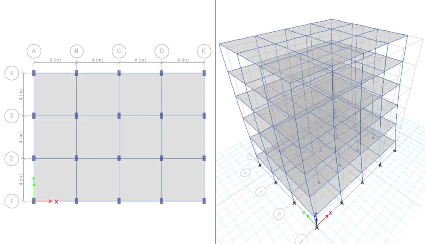
Building - E: (10 Storey Building with varying Column size along building height)
Step-1: First of all copy the pervious G+4 Building work file and paste in another folder
Step-2: Open copied file
Step-3: click on Define and select Section properties than select frame section add new sectional property (C 0.60 x 0.60)
Step-4: Assign 0.60 x 0.60 size for bottom 5 storeys and 0.40 x 0.40 size for top 5 storeys using Set building view limits in View tab.
Step-5: check the model and analyze the model for deflections.
Result:
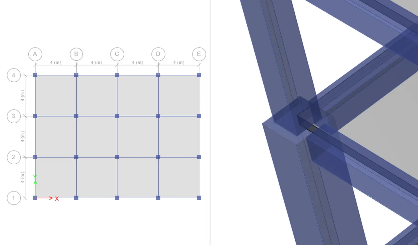
Building - F: (10 - storey building)
Step-1: First of all copy the pervious G+4 Building work file and paste in another folder
Step-2: Open copied file
Step-3: Remove the old section properties of column
Step-4: add new property is c o.60 x 0.60 (600 x 600) column
Step-5: Assign sectional property to the model
Step-6: check the model for errors and analyze the model for deflections .
Result:

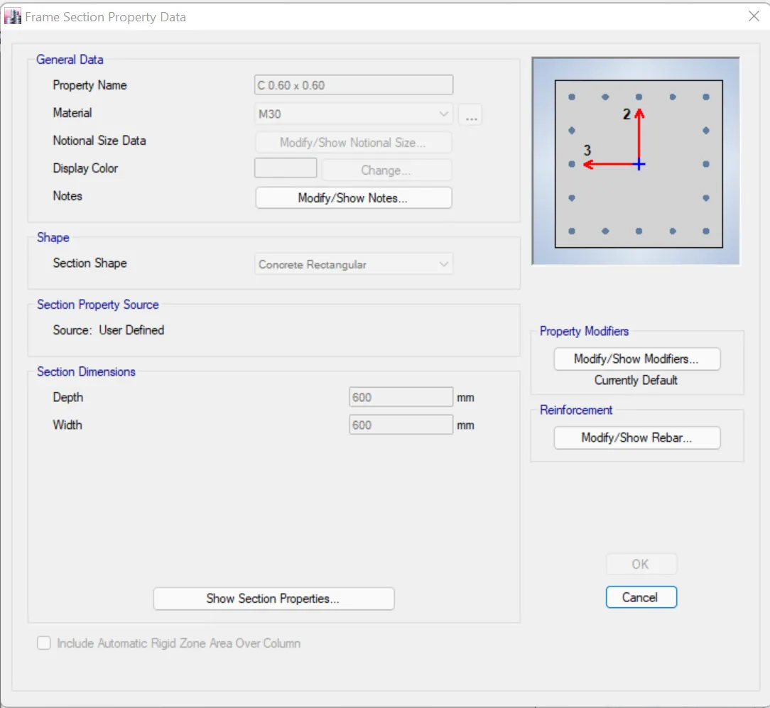
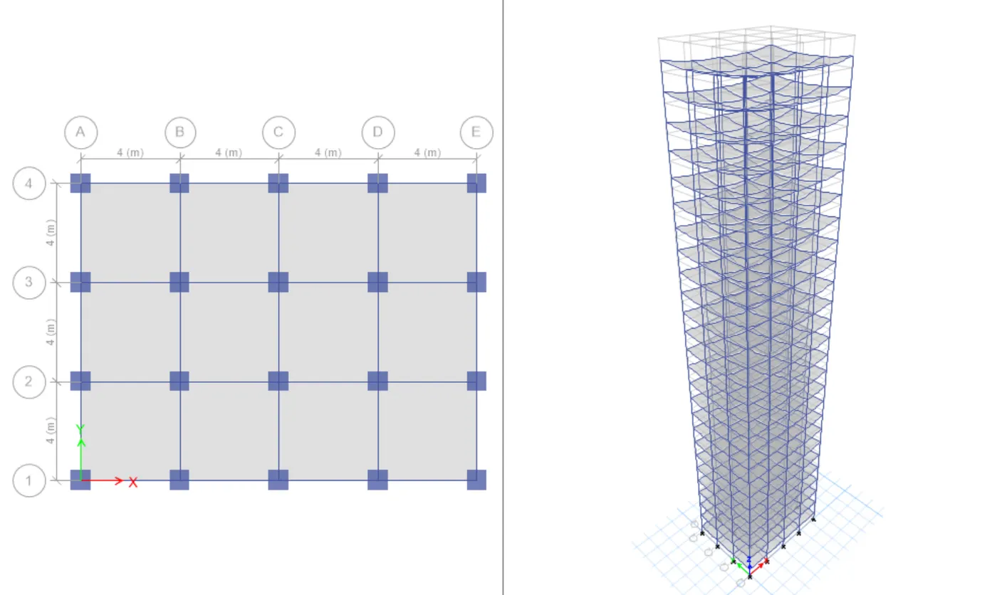
Building -G: (25 Storey Building with varying Column size along building height)
Step-1: First of all copy the pervious G+9 Building work file and paste in another folder
Step-2: Open copied file
Step-3: click on Define and select Section properties than select frame section add new sectional property (C 0.60 x 0.60)
Step-4: Assign 0.80 x 0.80 size for bottom 10 storeys, 0.60 x 0.60 size for middle 10 storeys and 0.40 x 0.40 size for top 5 storeys using Set building view limits in View tab.
Step-5: check the model and analyze the model for deflections.
Result:
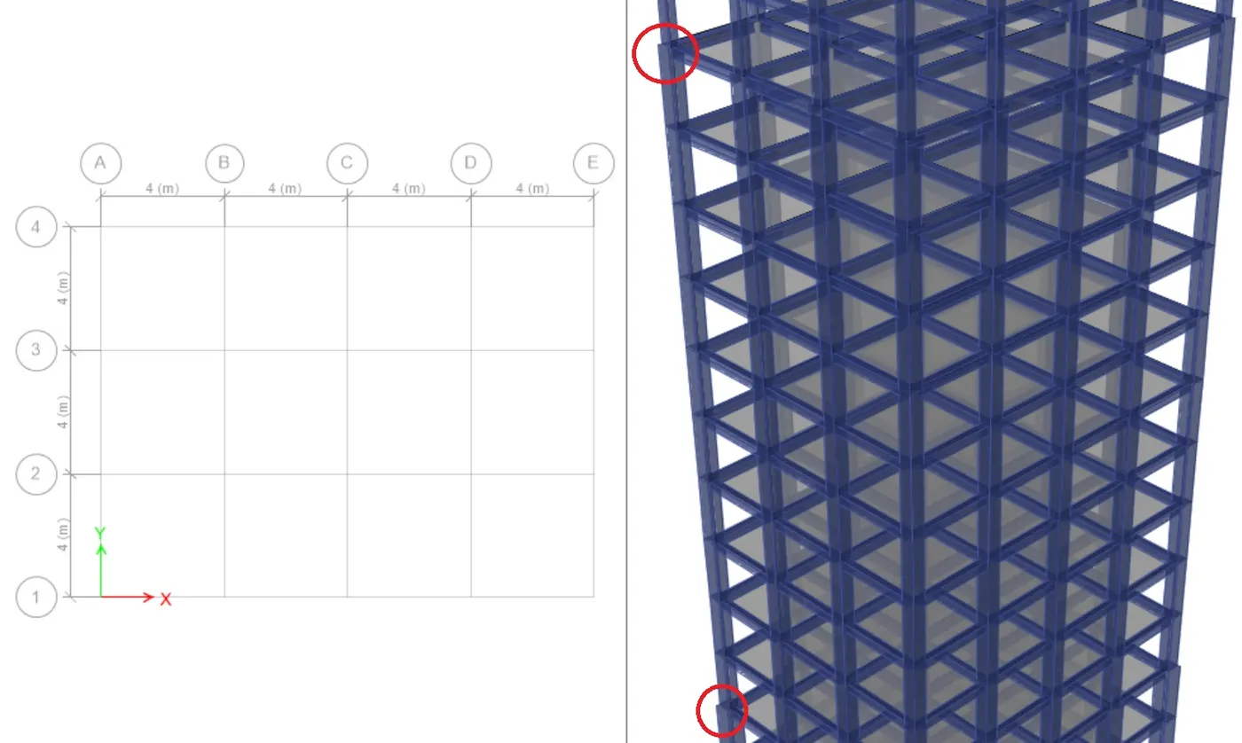
Building - H: (25 - storey building)
Step-1: First of all copy the pervious G+25 Building work file and paste in another folder
Step-2: Open copied file
Step-3: Remove the old section properties of column
Step-4: add new property is c o.80 x 0.80 (800 x 800) column
Step-5: Assign sectional property to the model
Step-6: check the model for errors and analyze the model for deflections .
Result:
Building - J: (25 - storey building with imposed mass 10% larger than Building-H)
Step-1: First of all copy the Building-H work file and paste in another folder
Step-2: Open copied file
Step-3: click on assign > Shell loads > uniform
Step-4: increase load into 10% means 3 KN/m2 to 3.3 KN/m2
Step-5: check the model for errors and analyze the model for deflections.
Building - K: (25 - storey building with imposed mass 20% larger than Building-H)
Step-1: First of all copy the Building-H work file and paste in another folder
Step-2: Open copied file
Step-3: click on assign > Shell loads > uniform
Step-4: increase load into 10% means 3 KN/m2 to 3.6 KN/m2
Step-5: check the model for errors and analyze the model for deflections.