Project 1_Comparative study of different storey buildings for Seismic forces
AIM : Comparative study of different storey buildings for Seismic forces.
INTRODUCTION:
- Buildings oscillate during earthquake shaking. The oscillation causes inertia force to be induced in the building.
- The intensity and duration of oscillation, and the amount of inertia force induced in a building depend on features of buildings, called their dynamic characteristics, in addition to the characteristics of the earthquake shaking (beyond the control of an engineer) itself.
- The important dynamic characteristics of buildings are modes of oscillation and damping (assumed constant in most practical cases). A mode of oscillation of a building is defined by associated Natural Period and Deformed Shape in which it oscillates.
- Every building has a number of natural frequencies at which it offers minimum resistance to shaking induced by external effects and internal effects.
- Each of these natural frequencies and its associated deformation shape of a building constitute a natural mode of oscillation.
- The mode of oscillation with smallest natural frequency and largest natural period is called fundamental mode and the associated natural period, T1 is called Fundamental natural period.
- Mode shapes of oscillation associated with a natural period of a building is the deformed shape of the building when shaken at the natural period. Hence, a building has as many mode shapes as the number of natural periods.
In this project we need to find out the effects of various parameters on Natural period of the building as well as on the mode shapes of oscillations, details of which are given below:
Factors affecting Natural period of building:
Effect of stiffness on T:
Compare fundamental natural periods of buildings E & F as well as G & H. Why is there a marginal or significant difference in the fundamental natural periods?
Effect of mass on T:
Compare fundamental natural periods of buildings H, J and K. Have the buildings become more flexible or stiff due to change in mass?
Effect of Building Height on T:
How does the fundamental natural periods of Buildings A, B, F and H change with change in building height?
Effect of Column Orientation on T:
How does the fundamental natural periods of Buildings B, C and D change with change in column orientation? Factors influencing the mode shapes of oscillations:
Effect of Flexural Stiffness of Structural Elements on mode shapes:
Compare fundamental mode shape of Building B in two situations when flexural stiffness of beams relative to that of adjoining columns is very small versus when it is large.
Effect of Axial Stiffness of Vertical Members on mode shapes:
Compare fundamental mode shape of Building H in two situations when axial cross-sectional area of columns is very small versus when it is large.
Effect of Degree of Fixity at column bases on mode shape: Compare fundamental mode shape of Building B in two situations when base of columns is pinned versus when it is fixed.
PROCEDURE :
1) Building A :
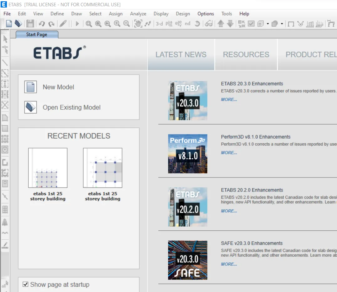
Step 1- Open the etabs software and click on new model option and select the built-in option and press ok.
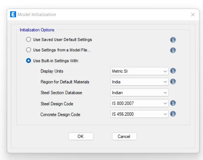
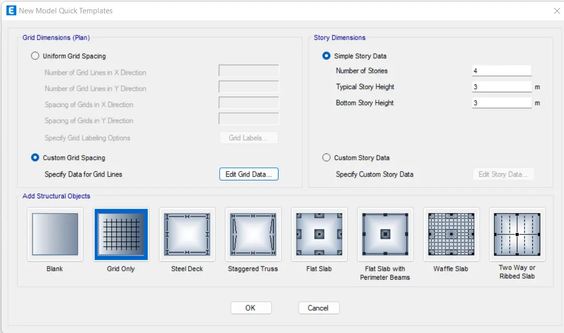
Step 2- Set grid spacing and custom storey data from quick templet and go to edit custom grid spacing and set number of bay and spacing between two grids and press ok.
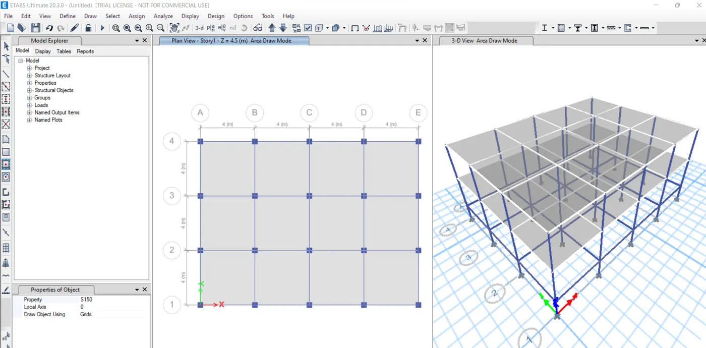
Step 3- Go to material proprty from define and add new material of concrete M30 and steel fe 415
Step 4- Add column frame and beam section according to given size and material from the frame properties.
Step 5-Add the slab section and add 150mm thick membrane slab with M30 grade concrete from define tab.
Step 6- For load patterns click on load patterns option from define tab and add load for wall and earthquake in X and Y direction respectively.
Step 7- For mass source add 1 for dead load and wall and 0.25 for live load respectivly.
Step 8- Go for load cases and check all the loads are appropriate.
Step 9- Create load combination.
Step 10- For column modelling click on draw column option and change working plane as all stories.
Step 11- For beam modelling go to quick draw beam and change working plane as all storey and draw the beam.
Step 12- For drawing slab go to quick draw slab and draw only for storey one and two.
Step 13- Now assign loads, For wall assign load of 10 KN/m and for slab assign load of 3 KN/m.
Step 14- For Diaphragms, select all the slabs from select option and assign diaphragm as D1.
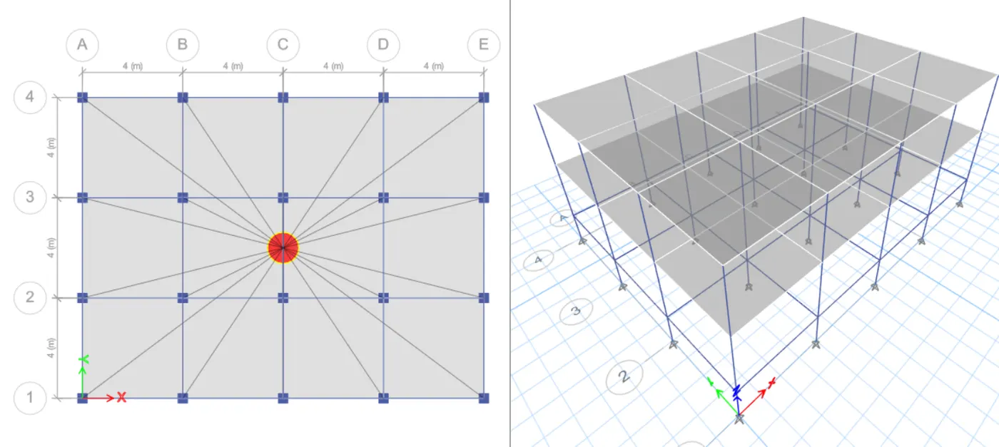
Step 15- Run analysis. After successfully running the analysis you will see the deformed shape of building.
- Similarly carry out the modelling for other buildings also using the steps above with different number of storey and different colunm sizes as given in the question.After running the analysis the results will look like images shown below.
2) Building B :
3) Building C:
4) Building D :
5) Building E :
6) Building F :
7) Building G :
8) Building H :
9) Building J :
- Imposed mass 10% larger i.e, Live load = 3.3kN/m2">m2
10) Building K :
- Imposed mass 20% larger i.e, Live load = 3.6kN/m2">m2
Effect of stiffness on T: ( considering first three modes)
- For buildings E & F:
-
Building E Building F Tx = 1.59s
Tx = 1.635s Ty = 1.638s
Ty = 1.683s Tz = 1.434s
Tz = 1.495s
-
- For buildings G & H:
-
Building G Building H Tx = 3.982s Tx = 4.158s Ty = 4.154s Ty = 4.338s Tz = 3.552s Tz = 3.773s
-
- T = (2π)⋅mk">(2π)⋅√mk(2�)⋅��. Hence, T∝m12">T∝m12�∝�12 and T∝1k">T∝1√k
Effect of mass on T : ( comparing H, J and K buildings)
| Building H | Building J | Building K |
| Tx = 4.158s | Tx = 4.166s | Tx = 4.174s |
| Ty = 4.338s | Ty = 4.346s | Ty = 4.354s |
| Tz = 3.773s | Tz = 3.778s | Tz = 3.784s |
Effect of building height on T: ( Comparing buildings A,B,F and H)
| Building A (2 storey) | Building B (5 Storey) | Building F (10 Storey) | Building H (25 Storey) |
| Tx = 0.439s | Tx = 0.988s | Tx = 1.635s | Tx = 4.158s |
| Ty = 0.447s | Ty = 1.009s | Ty = 1.683s | Ty = 4.338s |
| Tz = 0.397s | Tz = 0.89s | Tz = 1.495s | Tz = 3.773s |
- perios of the building increases as T∝1k">T∝1√k
Effect of column orientation on T: ( Comparing buildings B, C and D)
- In Building B, all the columns are square i.e 400mmx400mm, hence, the entire stiffness of the building will be equal in both X and Y direction.
| Building B (Column 400x400) |
| Tx = 0.988s |
| Ty = 1.009s |
| Tz = 0.89s |
- In Building C the longer edge of the column is arranged in X direction as shown in the figure below. Hence, the stiffness will be more in X direction compared to y direction. So, the time period will be lesser in X direction and it will be more in Y direction. That is the reason that for this building the time period in X direction is the least.
| Building C (Column 550x300) |
| Tx = 0.837s |
| Ty = 1.041s |
| Tz = 0.757s |
- In building D, the longer edge of the column is arranged in Y direction as shown below and as such the stiffness of the structure in the Y direction is higher compared to X direction. So, the time period of the structure will be lesser in the Y direction than in X direction.
| Building D (Column 300x550) |
| Tx = 0.916s |
| Ty = 1.109s |
| Tz = 0.869s |
Effect of flexural stiffness of structural elements on mode shapes:
Comparing the fundamental mode shapes of the building B in two situations:
1. For the original building B.
2. For the building B with flexural stiffness very small compared to the original building.
So, for this we need to develop another model B with lesser flexural stiffness of beam. In this model the moment of inertia about the 2 and 3 axis is changed to 0.1.
| Original building B | Modified building B1 |
| Tx = 0.988s | Tx = 1.768s |
| Ty = 1.009s | Ty = 1.791s |
| Tz = 0.89s | Tz = 1.696s |
From table, it is clear that the time period of the building has been increased. As the flexural stiffness of the beam is reduced, the building becomes more flexible and the time period is increased hence maintaining the inverse proportionality between time period and stiffness.
Effect of Axial stiffness of vertical members on mode shapes:
Comparing the mode shape of building H in two situation:
1. Original building H
2. When axial cross sectional area of the column is reduced by a factor of 0.1.
So, for this we need to develop another model H with smaller axial cross section of column.
| Original building H | Modified building H1 |
| Tx = 4.158s | Tx = 5.412s |
| Ty = 4.338s | Ty = 6.145s |
| Tz = 3.773s | Tz = 3.82s |
Here also, as the axial stiffness of column is reduced, the time period of the building is increased.
Effect of Degree of fixidity at column bases on mode shape:
Comparison of building B in pinned connection and fixed connection,
In pinned condition lateral sway will be more at bottom storey than upper storey and in fixed condition lateral sway is restricted at bottom storey. This condition is observed in above cases.
RESULT:
All the 10 model from A to K has been analyze and comparison study is also carried out with regarding to the time period of the structure.