Project 1_Comparative study of different storey buildings for Seismic forces
Project 1 - Comparative Study Of Different Storey Building For Seismic Forces
Answer:
Aim: To Model, Analyze and compare the results from different building using different floor levels and design parameters using ETABs software to understand their general seismic behavior.
Procedure:
1. Building A - Two Storey
i. Open ETABs Model
- Use the desktop shortcut or the start menu search to launch ETABS.
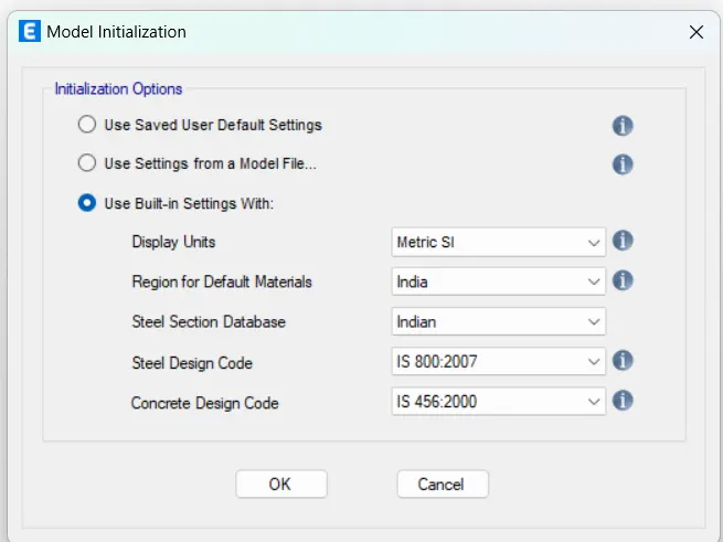
- Once the software is operational, select "new model" from the menu.
- A dialogue box where you can configure the codes and units to be used in your project will appear after you click on the new model.
- Consequently, make the necessary adjustments and press OK to begin modeling the first building in this project.
ii. Setting Up the Grid lines.
-
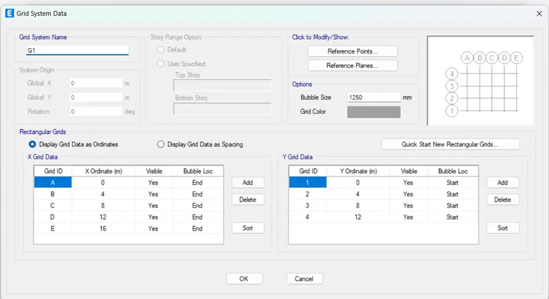
You must select the custom grid option in order to configure the grid data.
- Following that, a menu containing all the grid settings will appear.
- You can adjust the length, the number of orthogonal grids in both directions, the distance between each vertical and horizontal grid, and other options in the same menu.
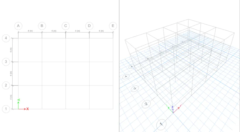
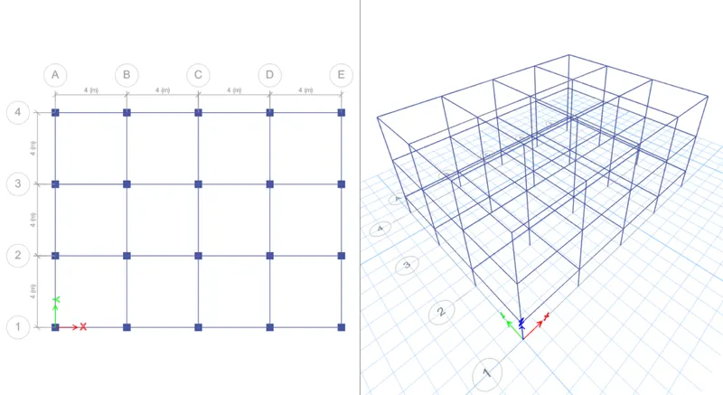
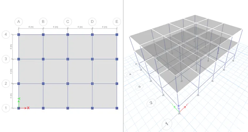
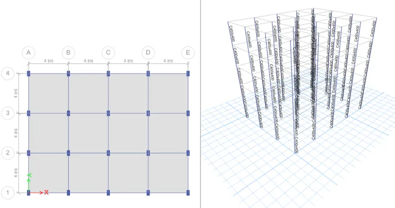
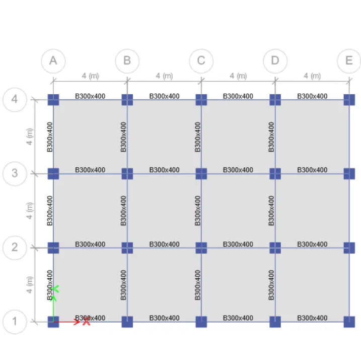
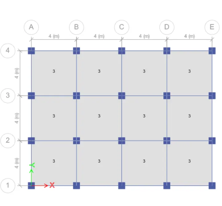
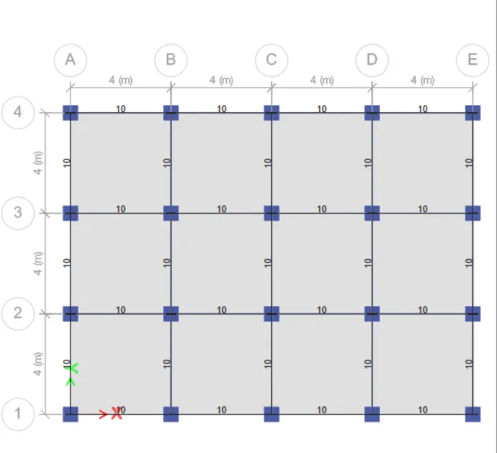
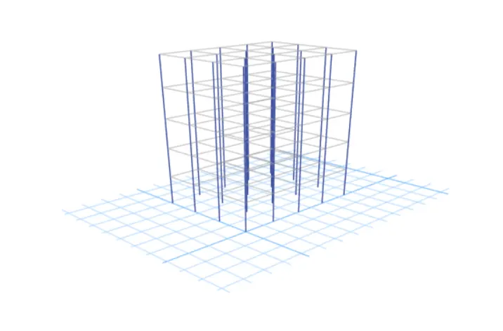
- Thus, by employing the same strategy, we have created a 4 x 3 bay grid with an interspace of 4 meters.
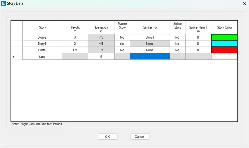
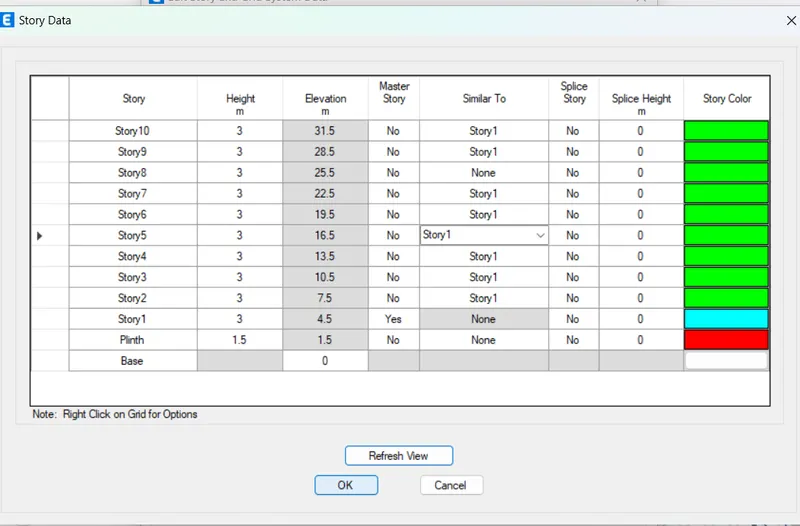
- Click on the custom story data option, just as we did when setting up the grids.
- Next, indicate the model's base level, plinth level, height of each floor, and total number of floors.
- As a result, we have planned a G+2 structure with a plinth height of 1.5 meters.
- Additionally, you need to fix the master story and all the related menu items.
- The first floor of our project is the master, and the remaining floors are all similar storeys.
- Once you've done this, your model is ready to run in ETABS with the specified grid and storeys.
iii. Defining the material property
- It is crucial to enter information in ETABS about the materials you intend to use for the project.
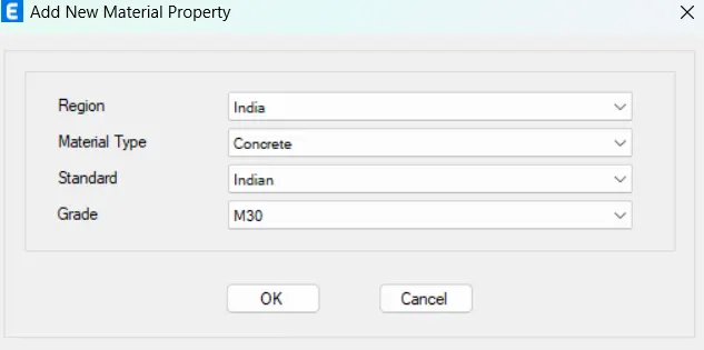
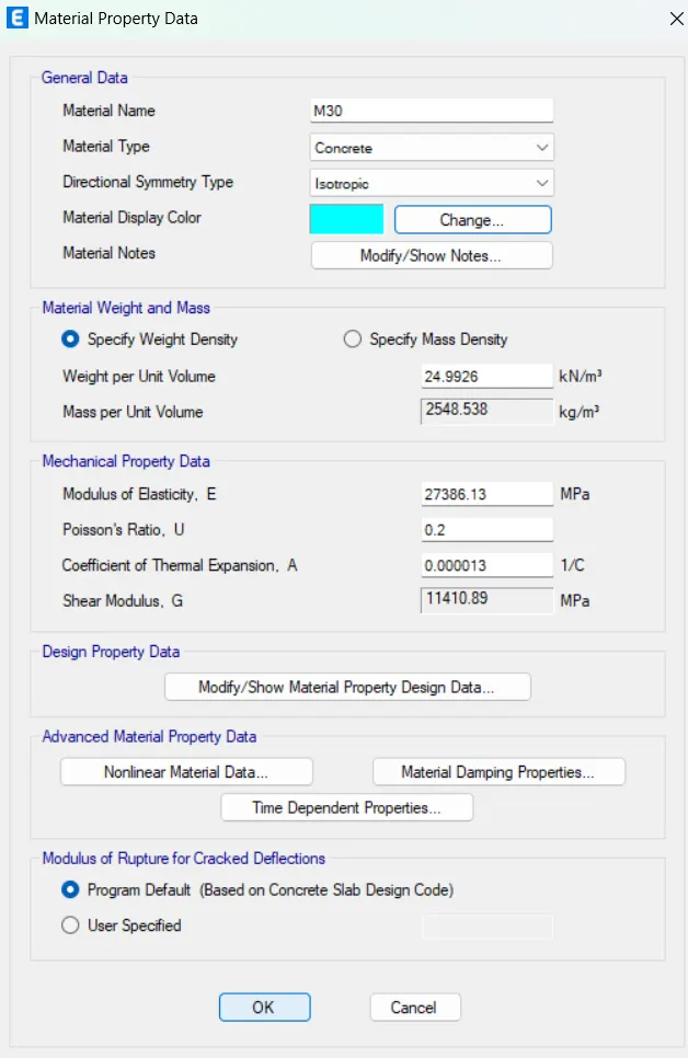
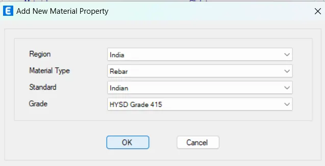
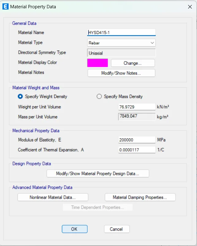
- Additionally, in accordance with the specifications, we must use Fe415 HYSD steel and concrete of the M30 grade for our model.
- So, select define>material>properties>add new>concrete/steel>grade>ok in order to define the same.
- However, since the Indian Standard Codes of Practices have already been specified, the M30 concrete and 450 steel are automatically added to the project.
iV. Defining Selection Properties
-
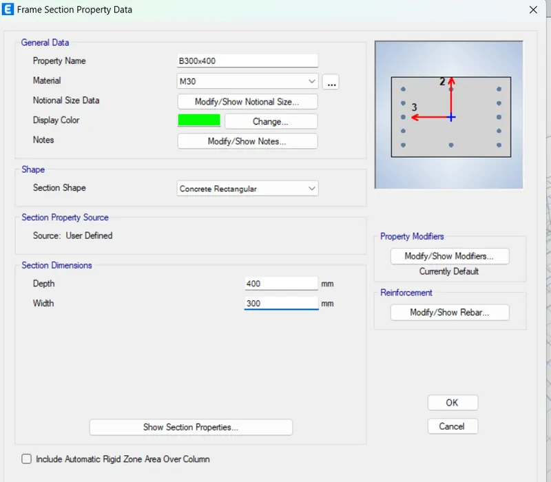
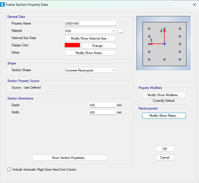
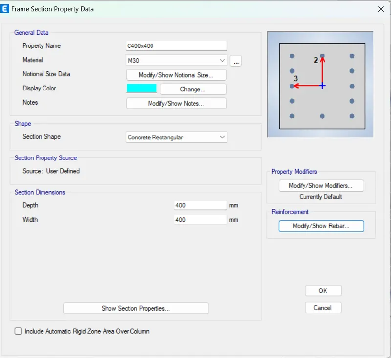
We use rectangular concrete sections for all the beams, columns, and slabs that make up the structure.
- So that we can use these sections repeatedly throughout the project, we must define that in the ETABS software.
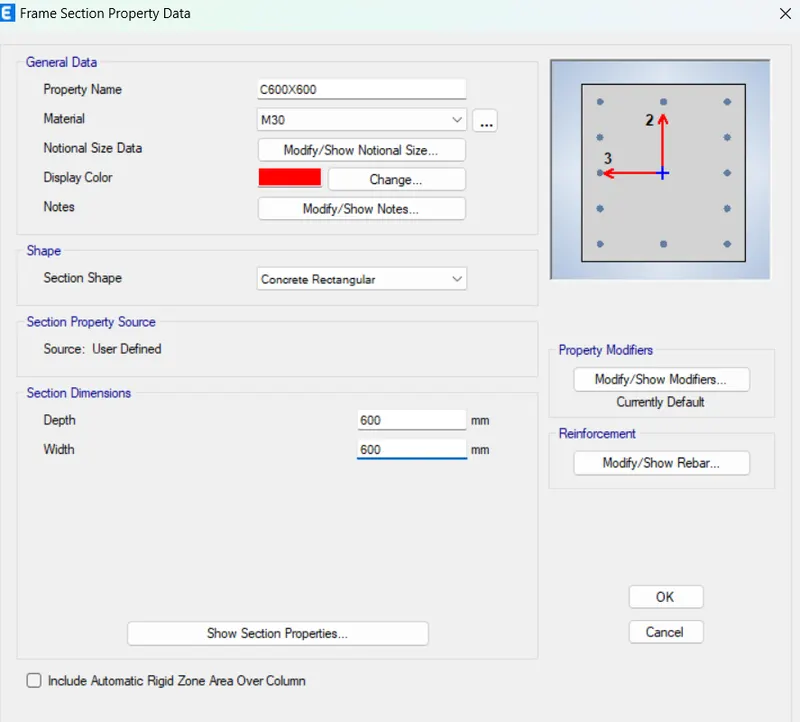
- Go to define > section properties > frame sections > concrete rectangular to do this.
- The dimensions of the column/beam and the type of reinforcement (HYSD415) to be used in the model can then be entered in the dialogue box that then appears on your ETABS screen.
As a result, you can define beams and columns from the same menu. -
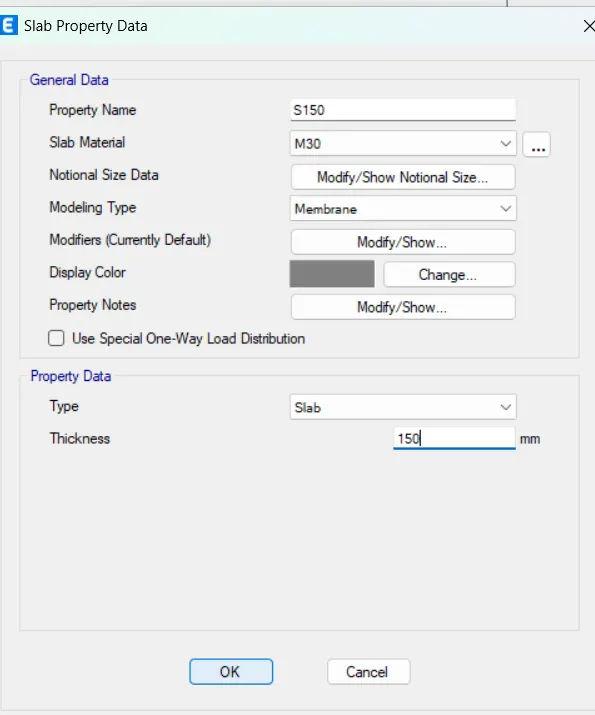
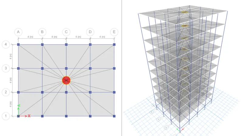
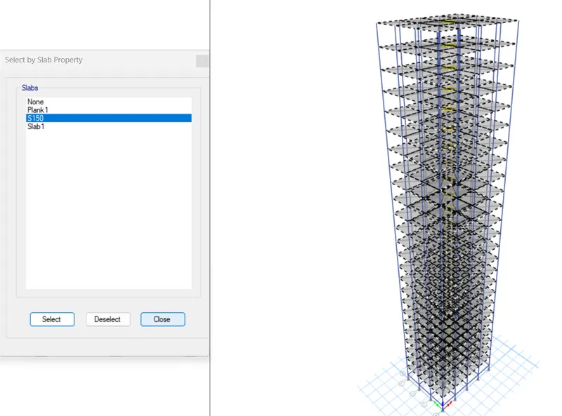
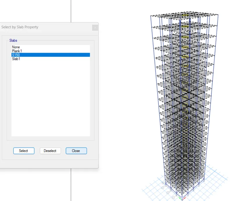
Go back to define>section>slab to define the slab section now.
- Once more, a menu will appear where you can enter the project's slab requirements.
V. Slab S150
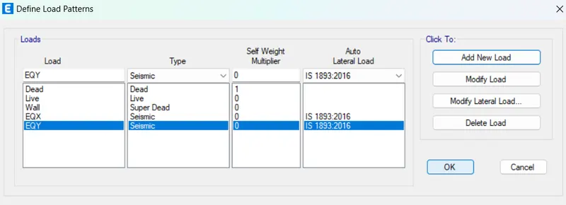
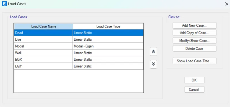
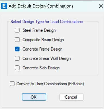
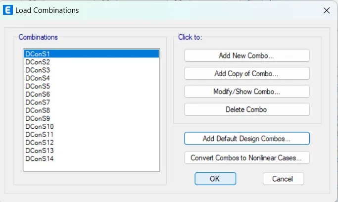
Vi. Defining the load patterns and load combination.
- Following the model's completion, we must now list the different kinds of loads anticipated to be placed on the structure over the course of its useful life.
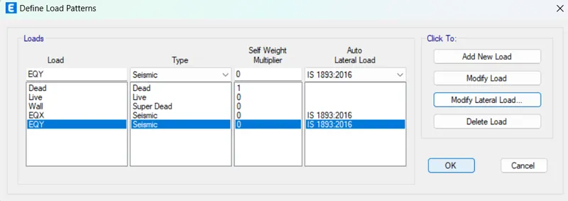
- Go to define>load patterns>add loads to do this.
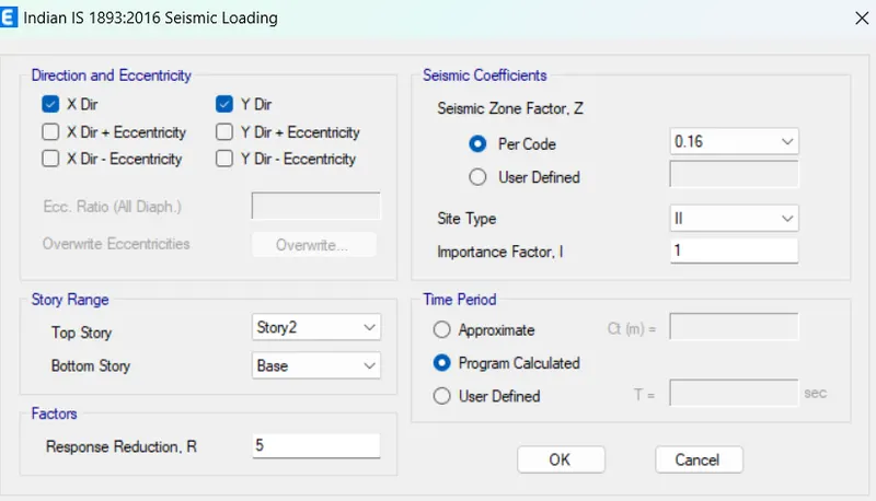
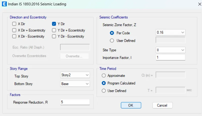
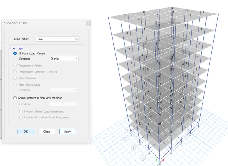
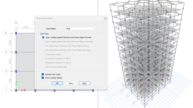
- You can add all the loads here, and for our project, we have the earthquake load in the x and y directions as well as the dead load, super dead load (brick wall load), live load, and other loads.
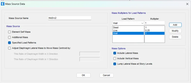
- Additionally, you must add 100% of the dead and super dead load as well as 25% of the imposed or live load when defining the mass source.
.
vii. Defining Columns, Beams, and Slab
-
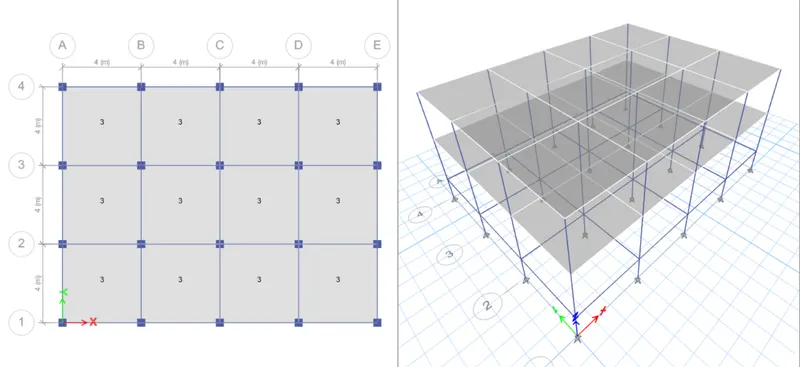
We can now proceed to draw each structural component in accordance with the specifications, having defined everything from the materials to the beams, columns, and slabs required for our structure.
-
And in order to do that, we can employ the quick draw tool commands in ETABS.
-
With the aid of this tool, you can draw every beam, floor, and column, as the name suggests.
-
Simply choose the appropriate tool, such as quick draw columns for drawing columns, and vice versa. then pick the appropriate section from the drop-down menu.
-
After that, all you have to do is open the plan view grid system and begin clicking on the grid locations where you want to place these structural components.
viii. Save the model and Run the Analysis.
-
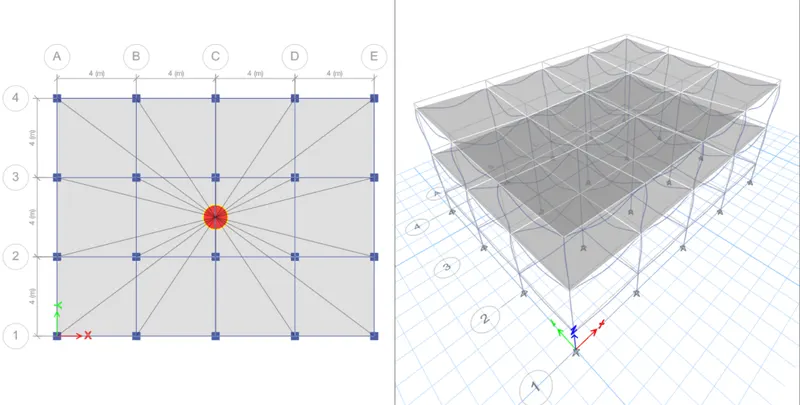
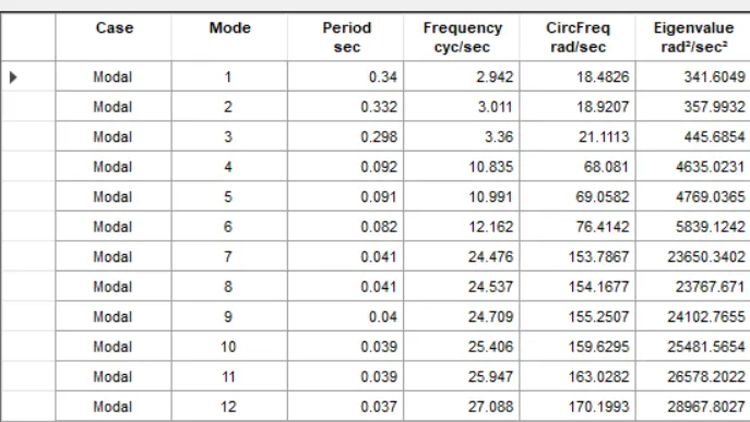
We can now move forward with running the analysis for this building since everything pertaining to our first model is finished.
- However, we must first save our project before running the analysis, so please do this in your system's preferred location.
-
The analysis for the current model can then be run by simply pressing F5 on your keyboard or by clicking the arrowhead present on the ETABS screen.
Result:
Model Response for Building A
1. Building B - Five Storey
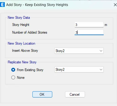
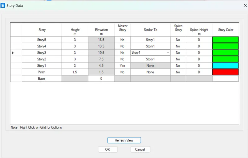
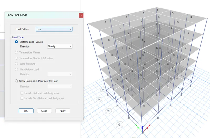
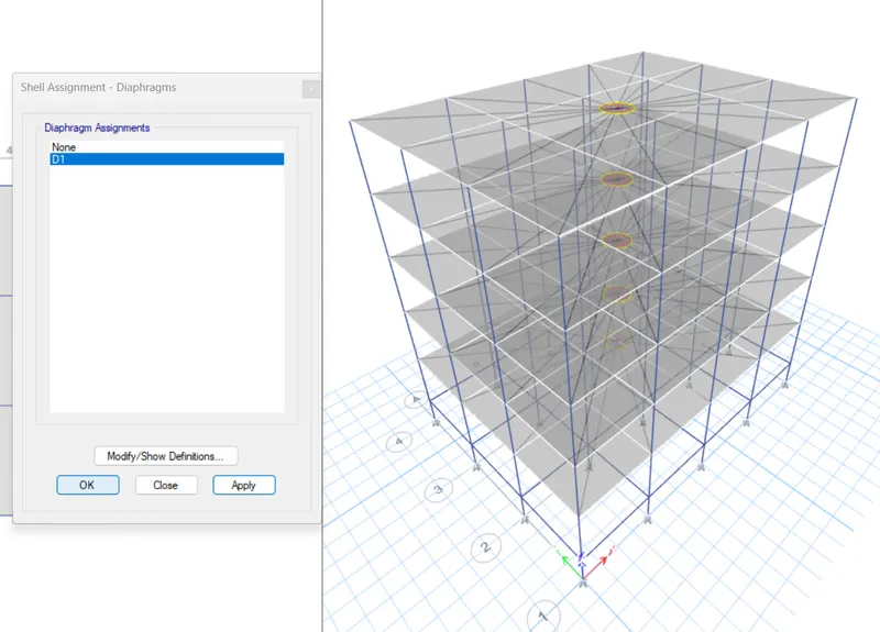
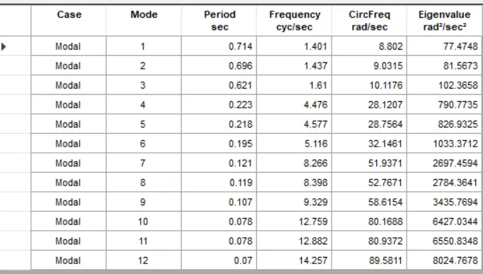
Simillay, for Building B use the option save as and only edit in storey make it as five storey building.
Result:
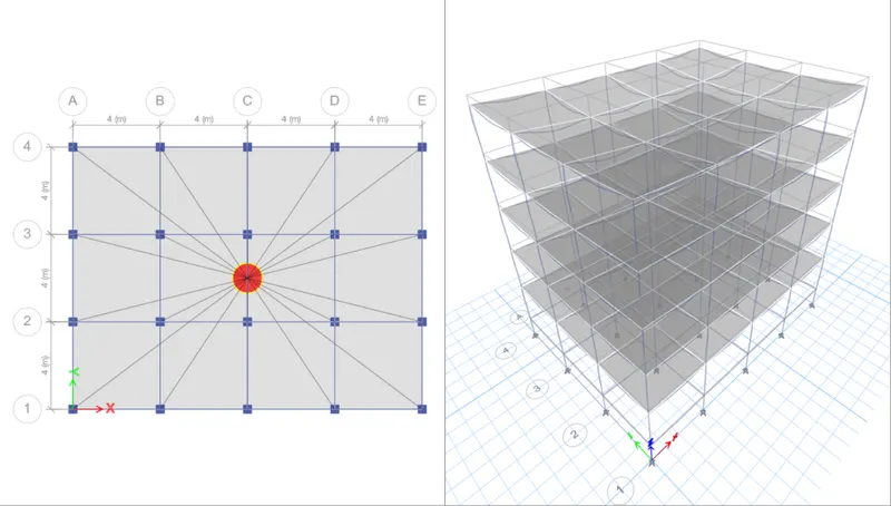
Model Response for Building B
3. Building C - Five Storey
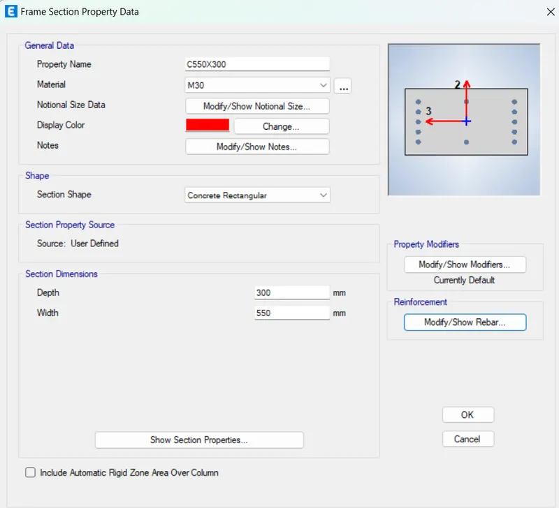
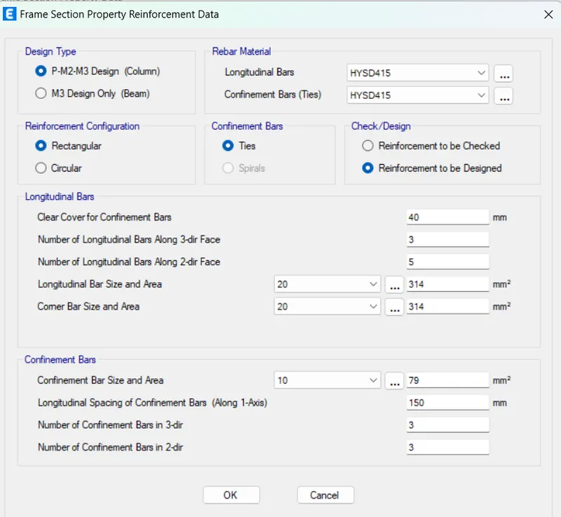
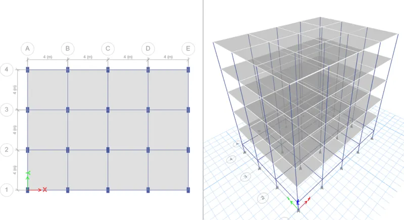
Simillay, for Building C use the option save as and only change the size of the column C550x300
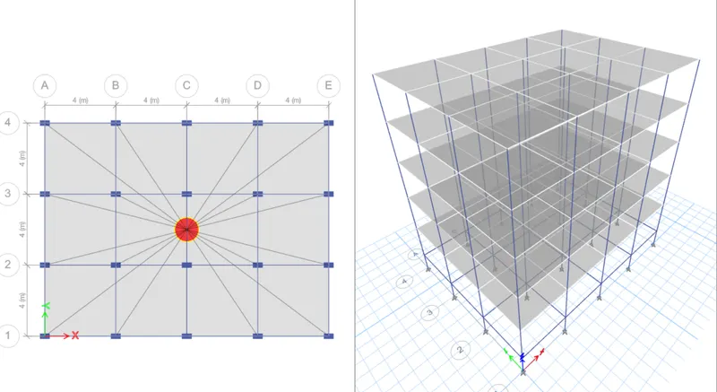
Result:
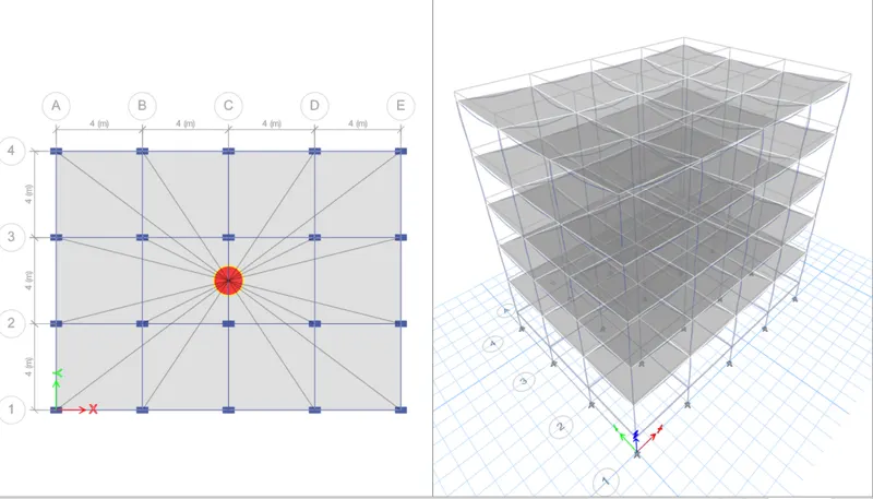
Model Response for Building C
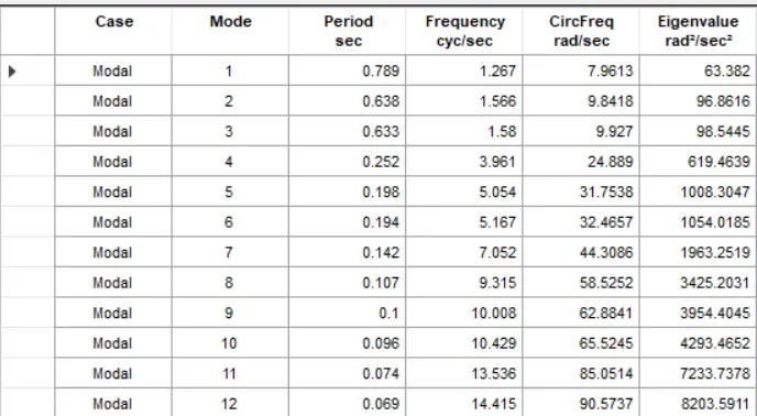
4. Building D - Five Storey
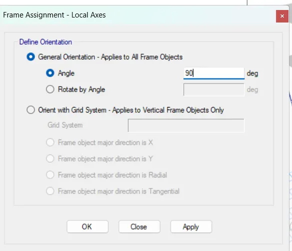
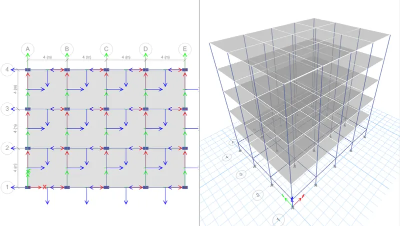
Simillay, for Building D use the option save as and only edit in local axis
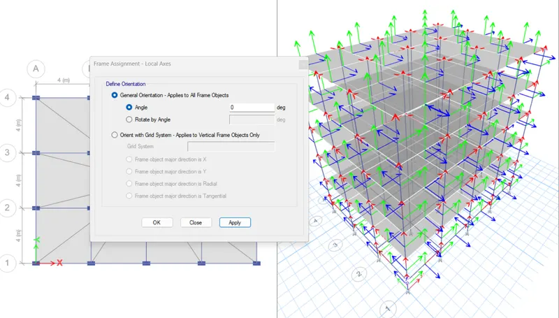
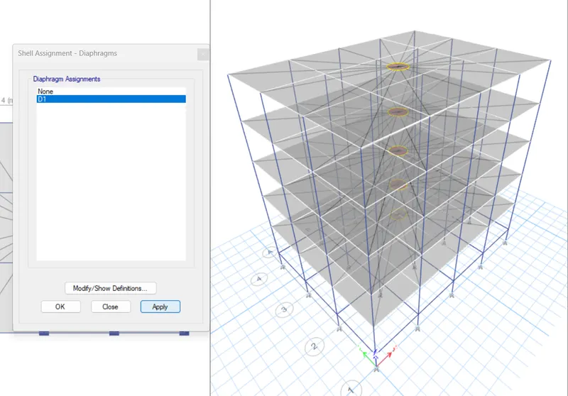
Result:
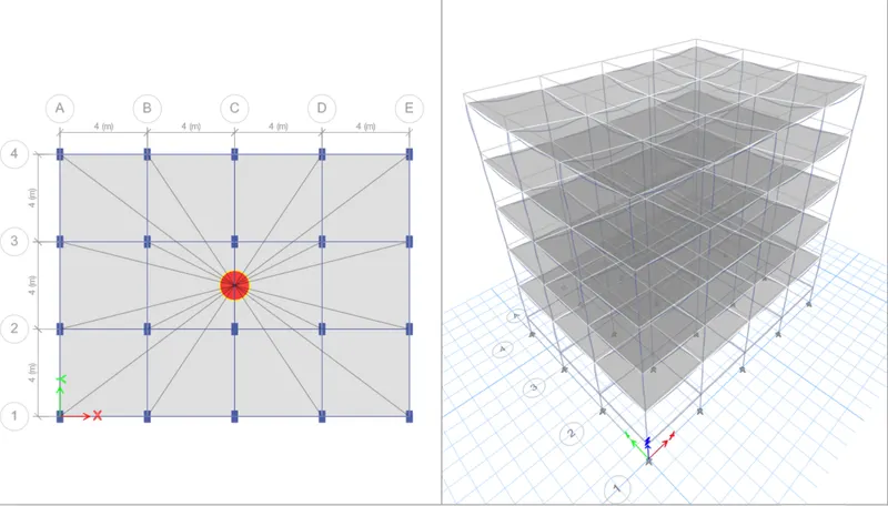
Model Response for Building D
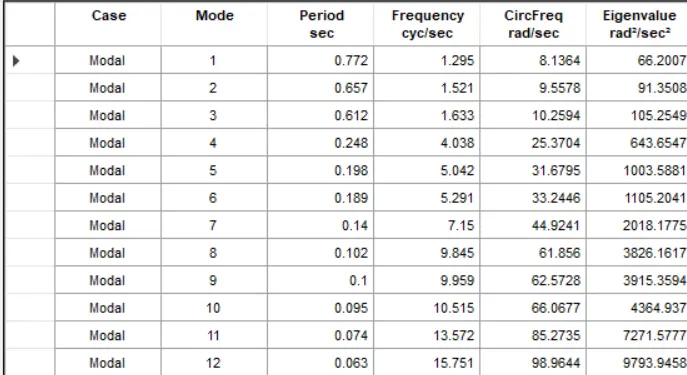
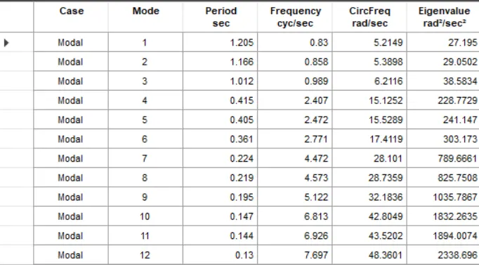
5. Building E - Ten Storey
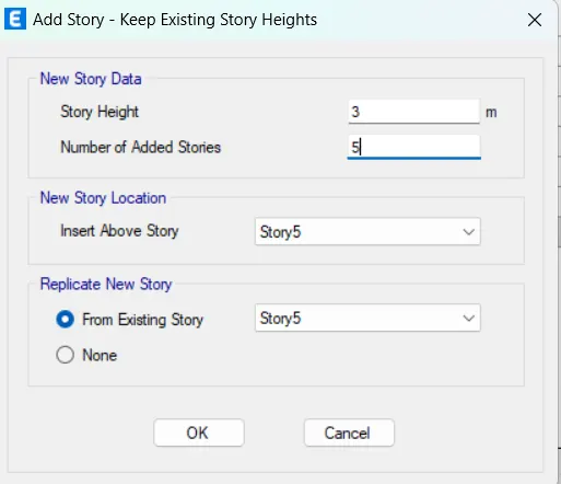
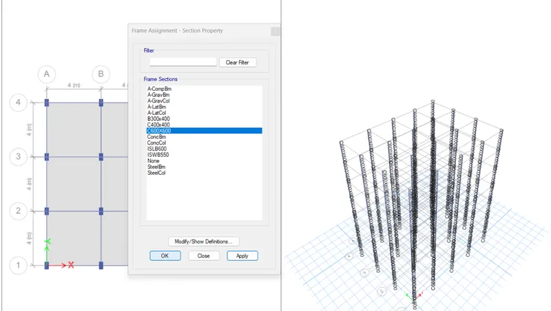
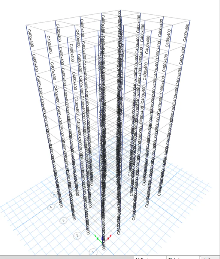
Simillay, for Building E use the option save as and only edit in storey make it as ten storey building and column size as
C600x600 for bottom five storey and C400x400 for top five storey
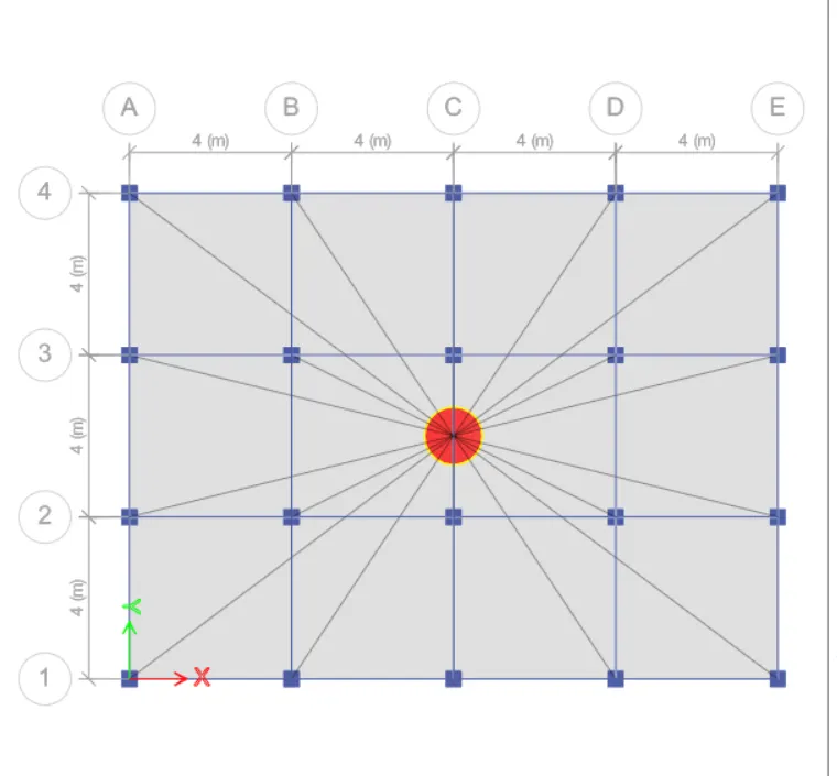
Result:
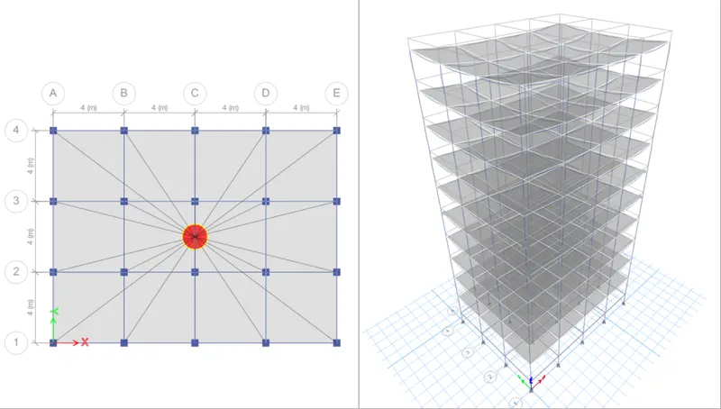
Model Response for Building E
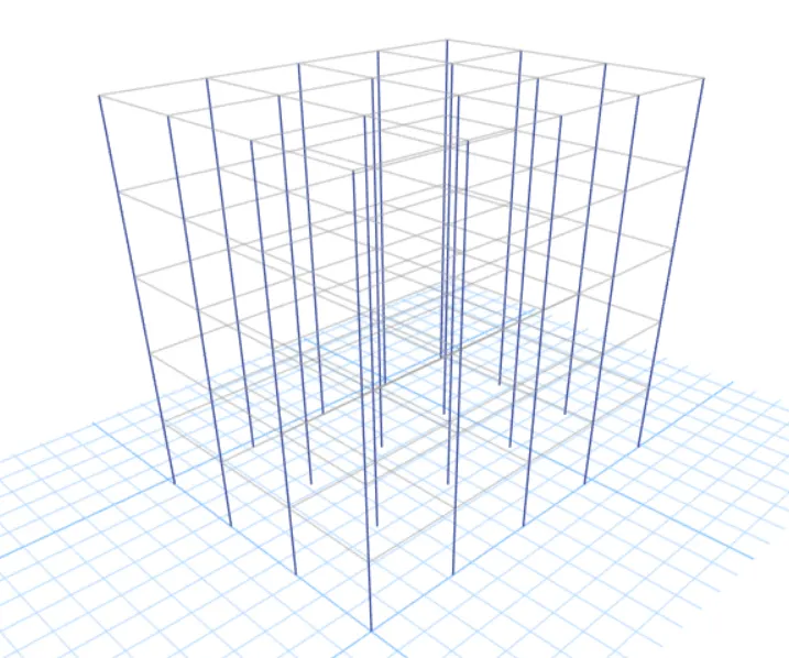
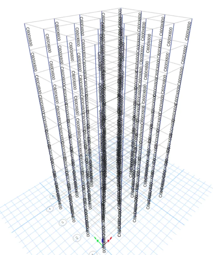
6. Building F - 10 Storey
Simillay, for Building F use the option save as and only edit in storey make it as ten storey building and all column sizes as
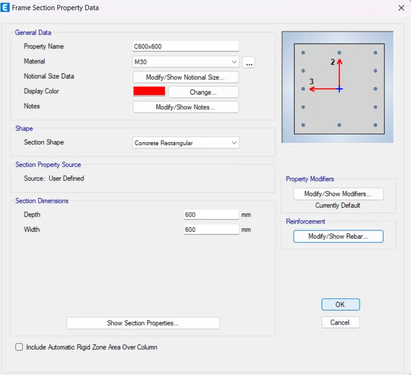
C600x600
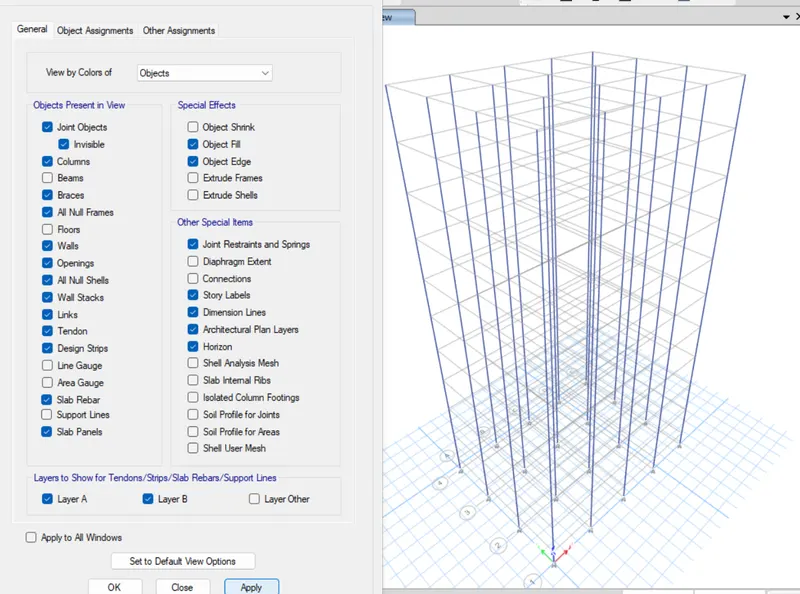

Result:
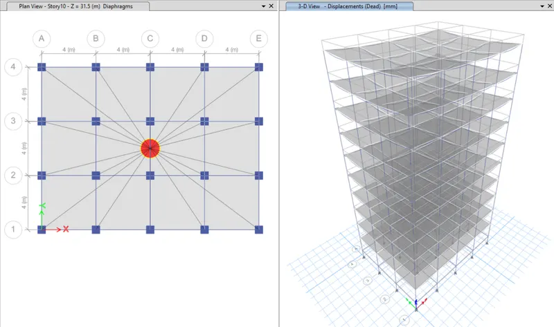
Model Response for Building F
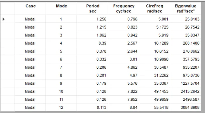
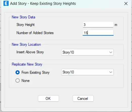
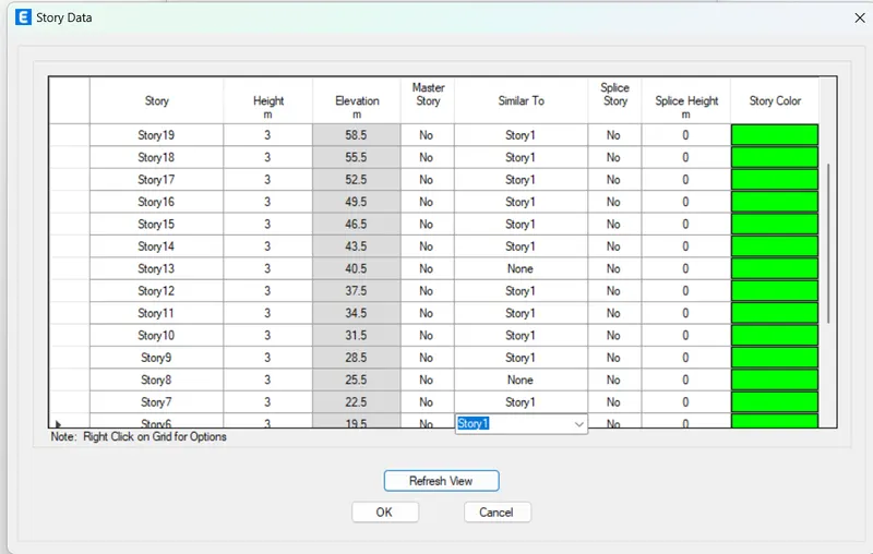
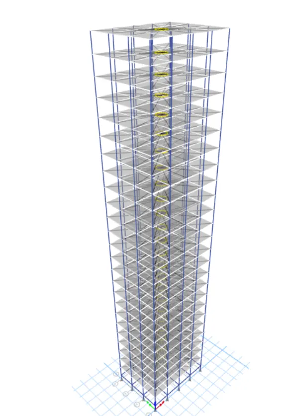
7. Building G - 25 Storey
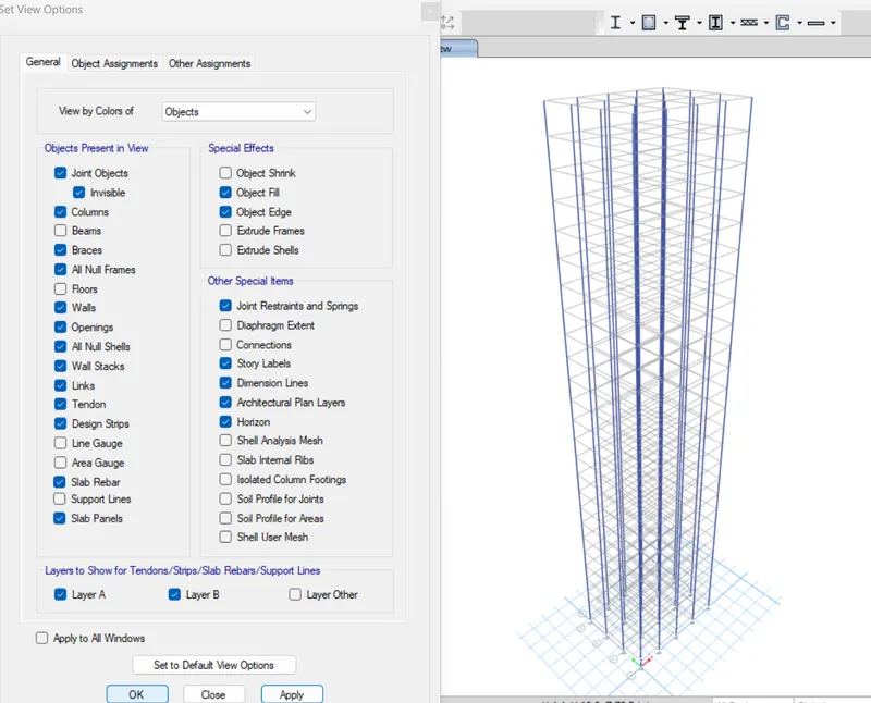
Simillay, for Building G use the option save as and only edit in storey make it as ten storey building and all column sizes as
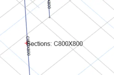
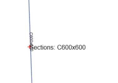
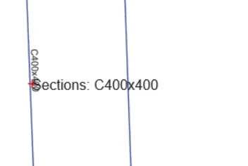
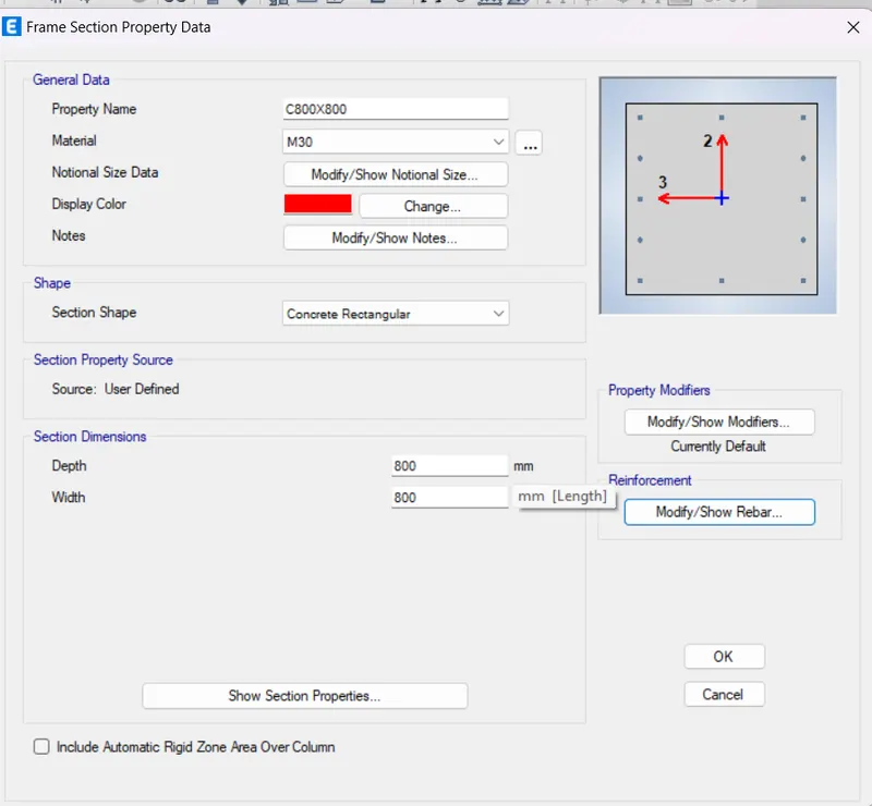
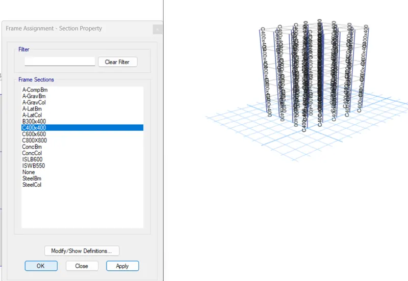
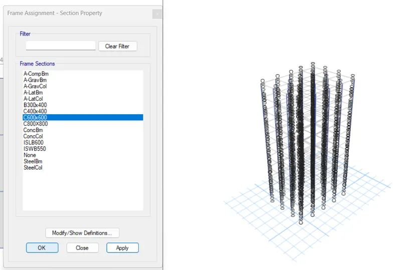
C800x800 from base upto storey 11 and C600x600 fro m storey 11 to storey 21 and C400x400 from storey 21 to 25
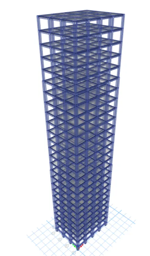
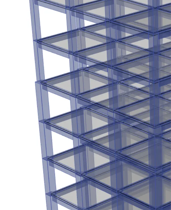
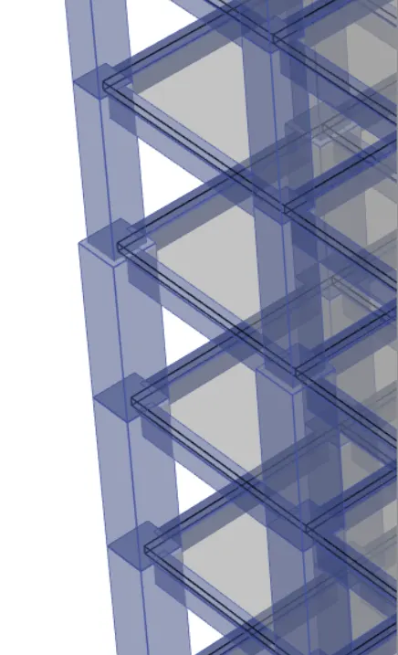
Result:
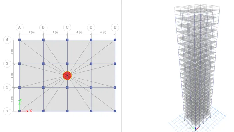
Model Response for Building G
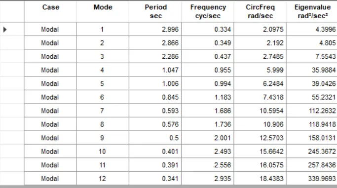
8. Building H - 25 Storey
Simillay, for Building H use the option save as and only edit in the size of the column and make all column size as C600x600
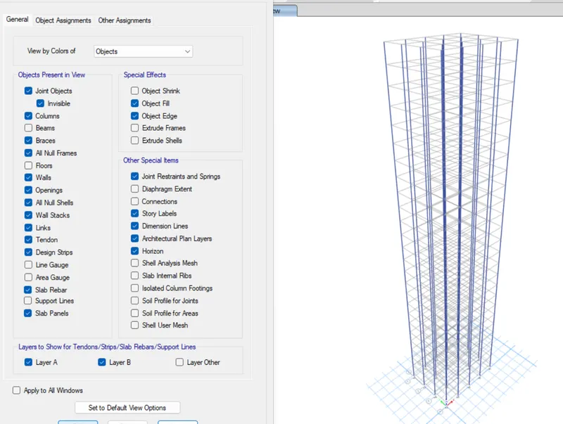
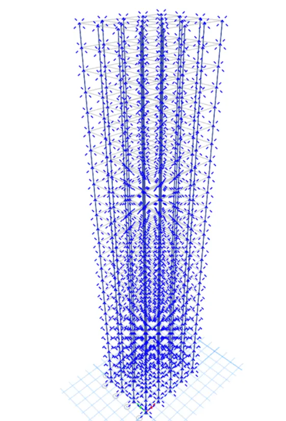
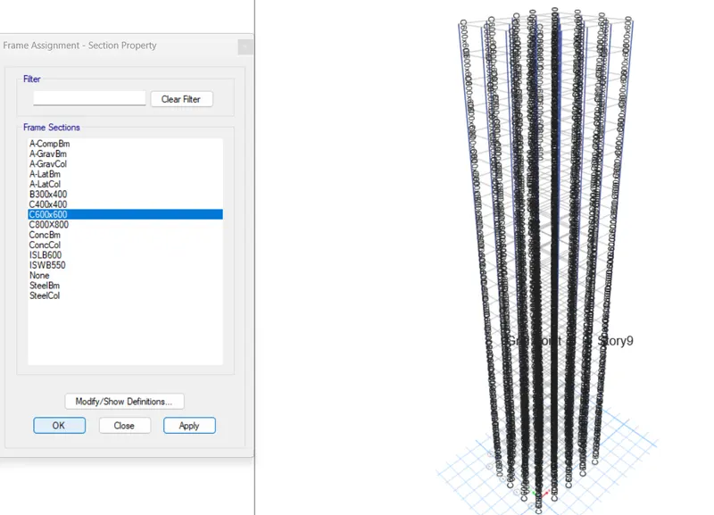
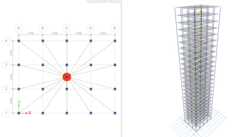
Result:
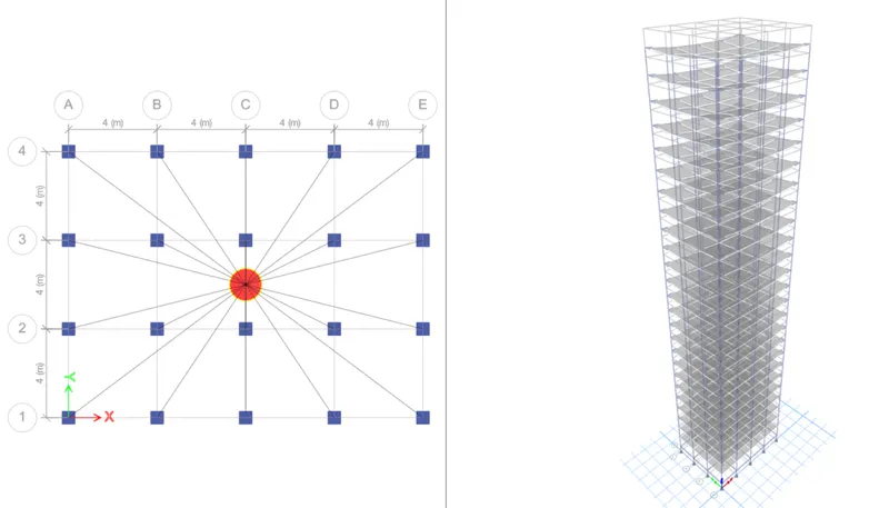
Model Response for Building H
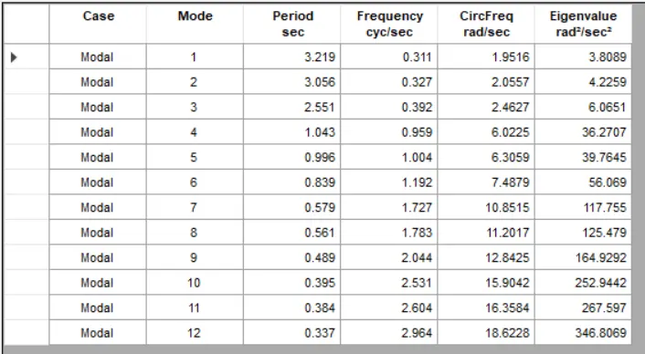
9. Building J - Two Storey
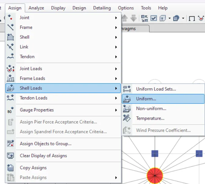
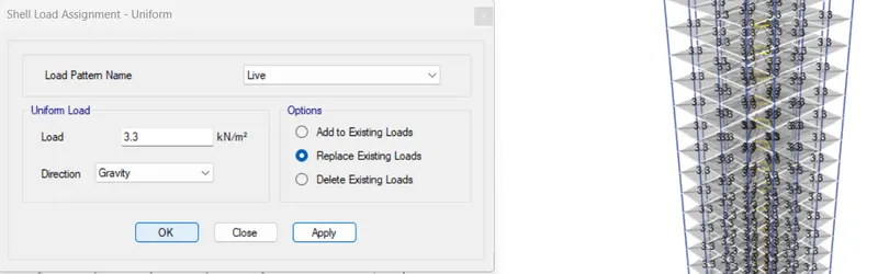
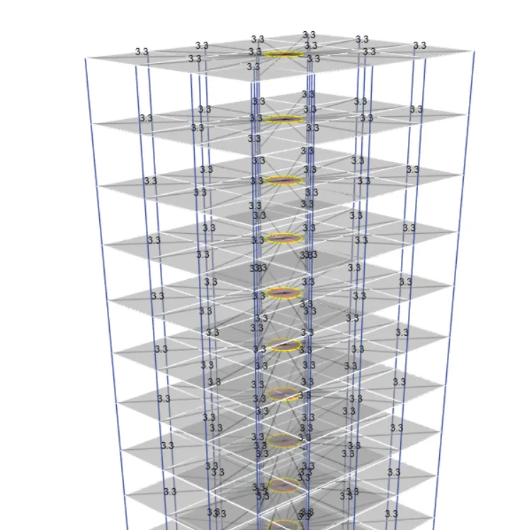
Simillay, for Building J use the option save as and only edit in live load make it as 3.3kN/m2
Result:
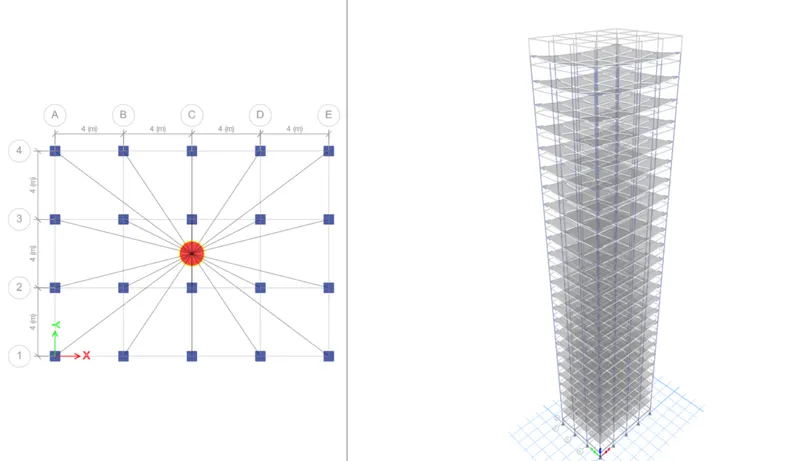
Model Response for Building J
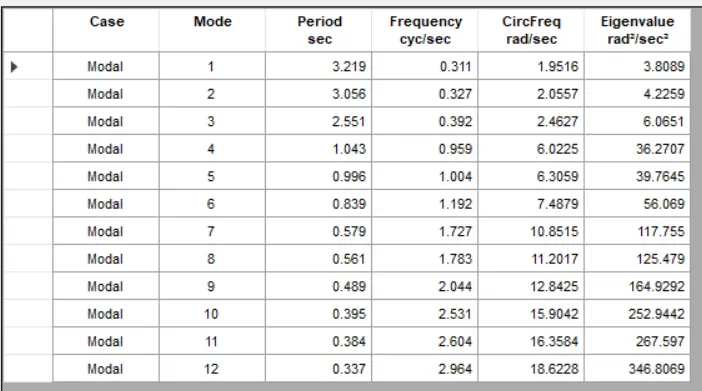
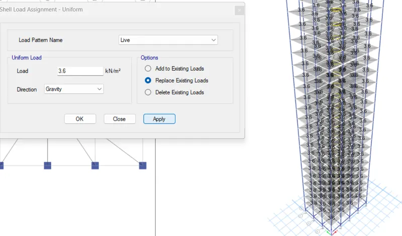
10. Building K - Two Storey
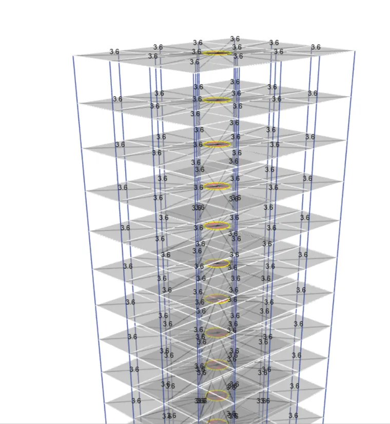
Simillay, for Building K use the option save as and only edit in live load make it as 3.6kN/m2
Result:
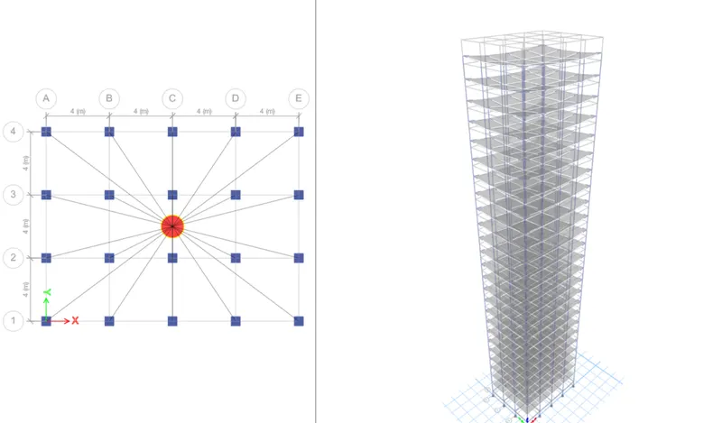
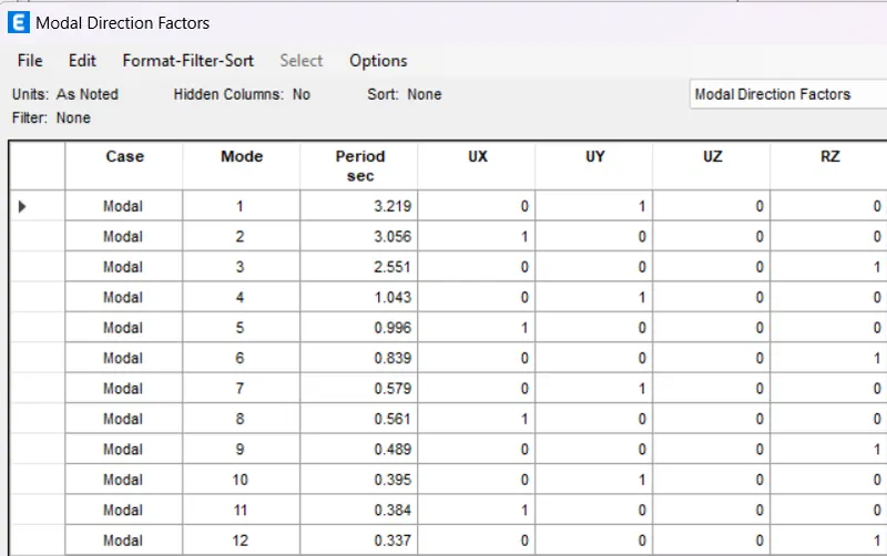
Model Response for Building K
-----------------------------Thank You----------------------------------