Project 1_Comparative study of different storey buildings for Seismic forces
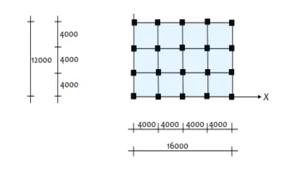
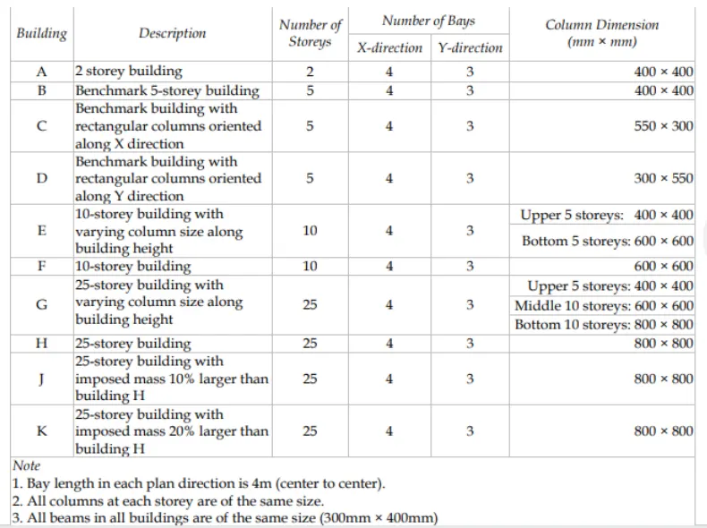
MODEL-A
Open the Etabs software
select a new model
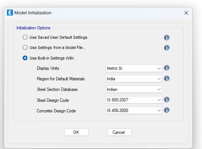
provide units & design code,concrete design code.
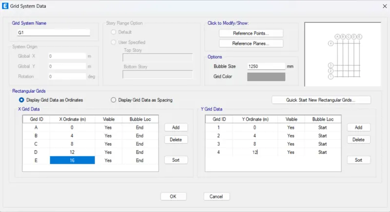
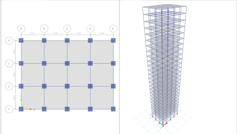
now arrange the grids in X,Y directions 4m spacing.
story 2, height of each story is 3m and plinth level is 1.5m.
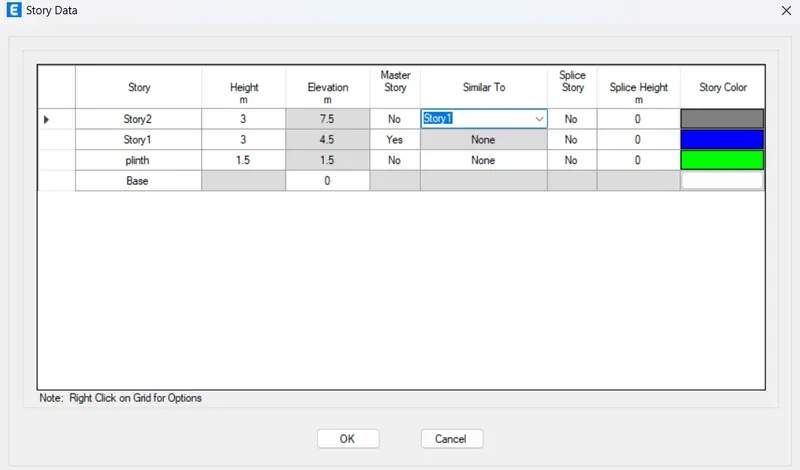
After setting the grid arrangement and story, plan view and 3d view of the model appear.
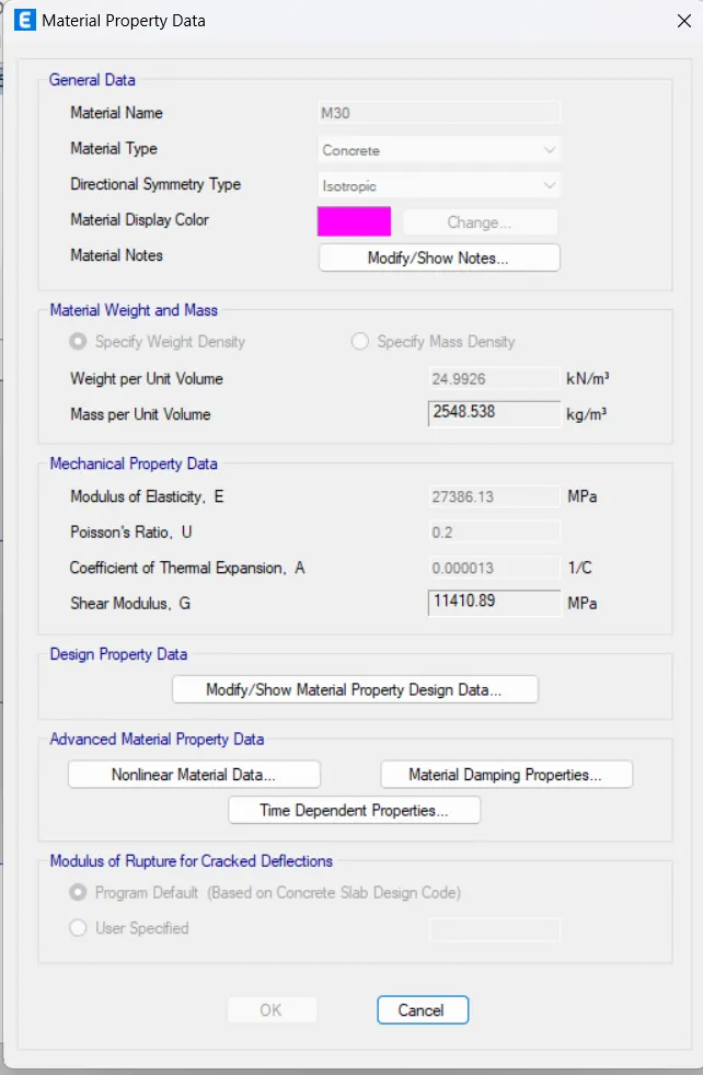
Now click on the Define ->material propert->add new material that is M30
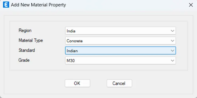
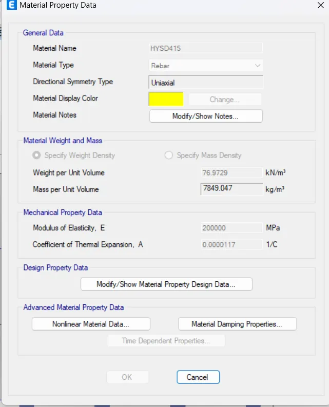
Add another new material as ->HYSD415
Now select the define->section propertys->frame section
create a new beam section select the shape give the size as B300x400
depth 400mm,width 300mm
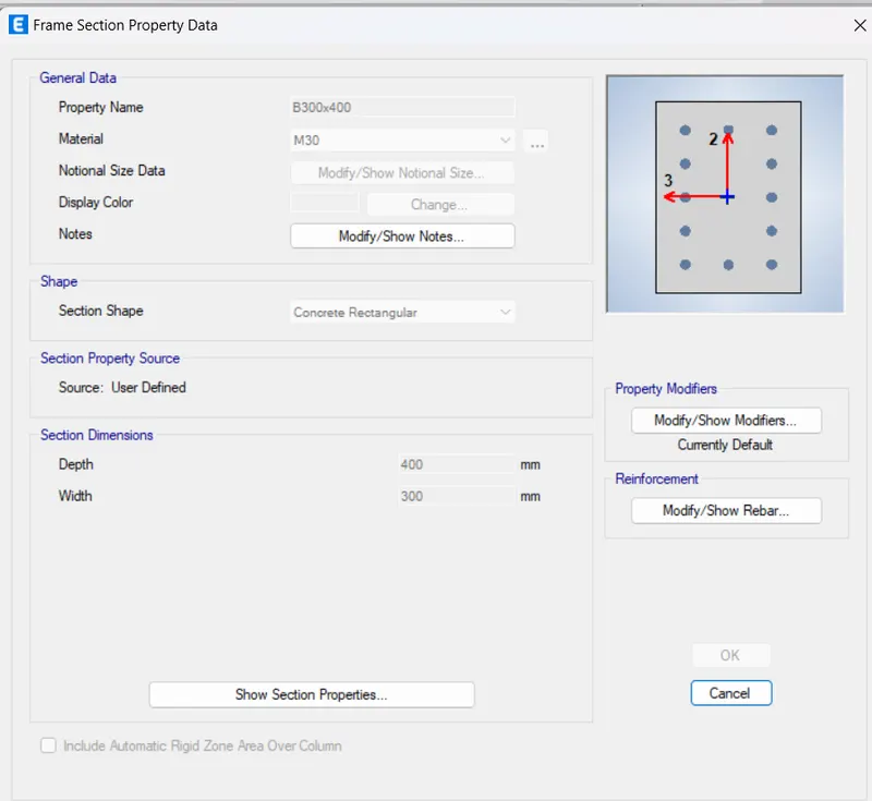
add column propery select shape, size as C400x400
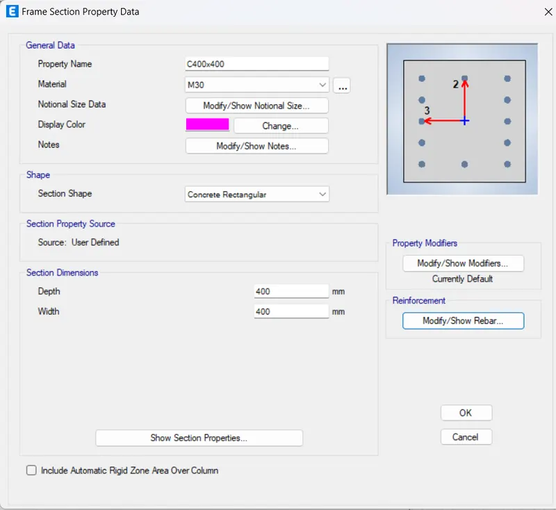
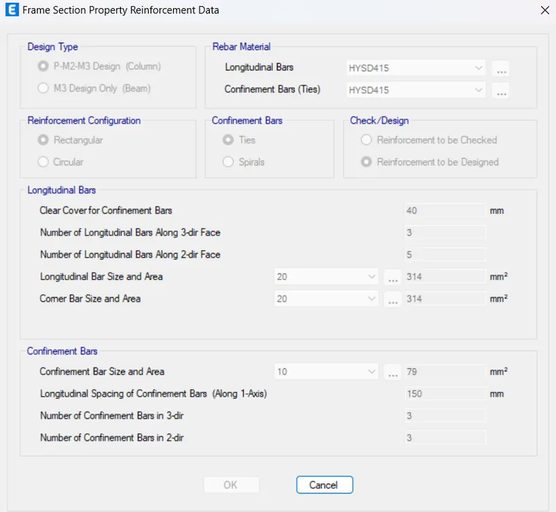
modify the reinforcement as shown below.
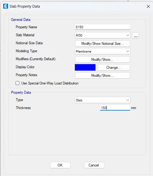
Again select define->section propert->slab section.
add new propert name it as S150 thickness of slab is 150mm
load patterns select define->load patterns
now add the loads as dead, live,wall,EQX,EQY by give codes
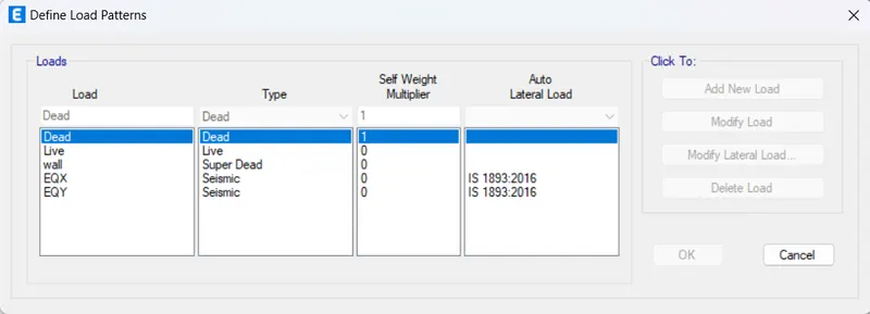
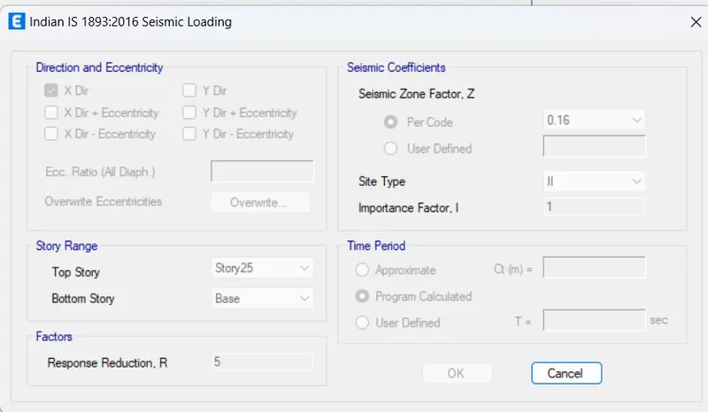
For EQX provide direction and eccentricity in x direction, soil type as type 2 and zone 3 assume other data same as in EQY also.
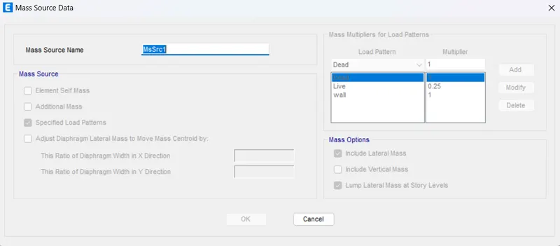
select define->mass source
provide the loads dead ,live, wall load as per codes.
by this we get to know how much mass should we considered for seismic lateral moment.
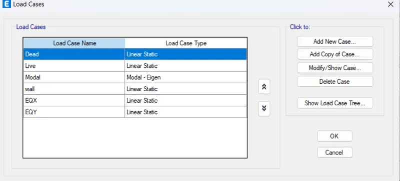
Check for load cases all are arranged or not
click on Define->load cases
create the load combination for concrete frame.
click on Define->load combination.
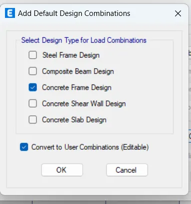
Now we get to modal select quick draw column,chose the property make sure that work in all story option.
select the grids and draw the column or use replicant option to draw the column.
After completing column select qucik draw beams do the as column.
For slabs click on plan->select the story1->chage it to similar story.
select the quick draw floor->chose S150->select the model for slab.
for selecting of beams, click on select->properties->frame section->B300x400
Assign frame load click on assign->frame loadapply the load.
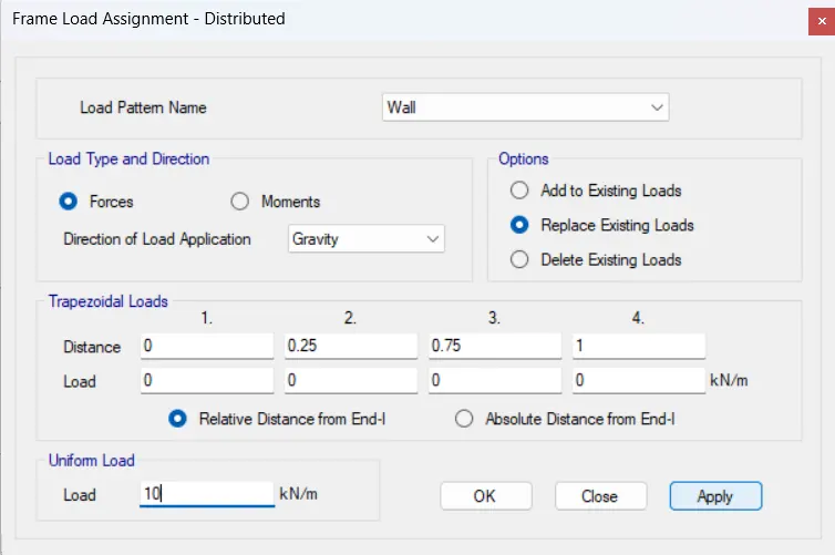
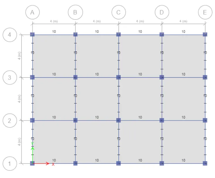
Now select all the slab click on select->properties->slab section->S150.
Now assign shell loads click on assign->shell load apply load.
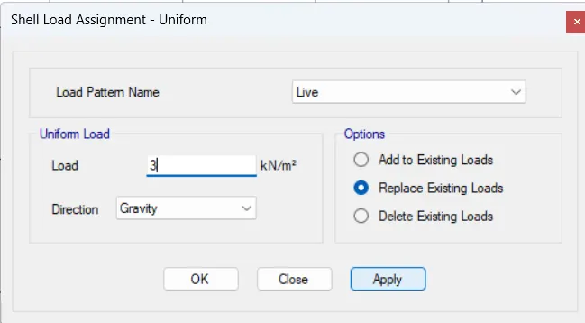
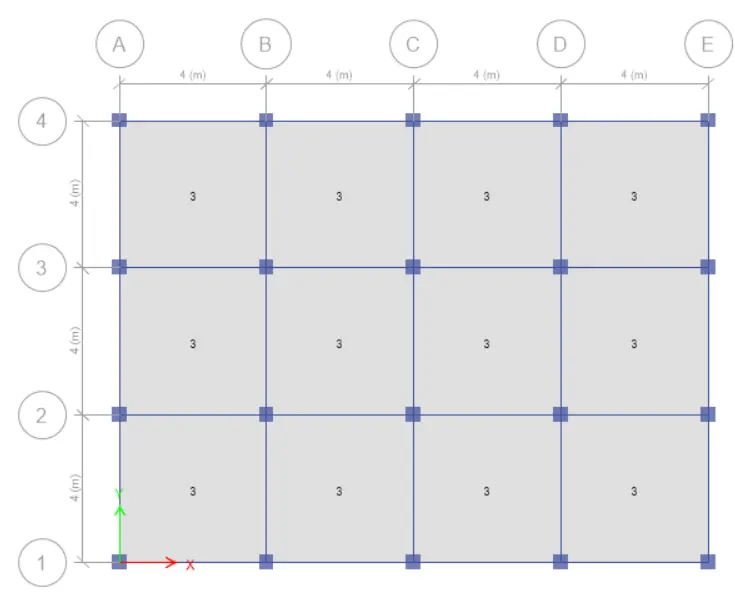
again select slab to assign diaphragms, click on assign->diaphragms select D1.
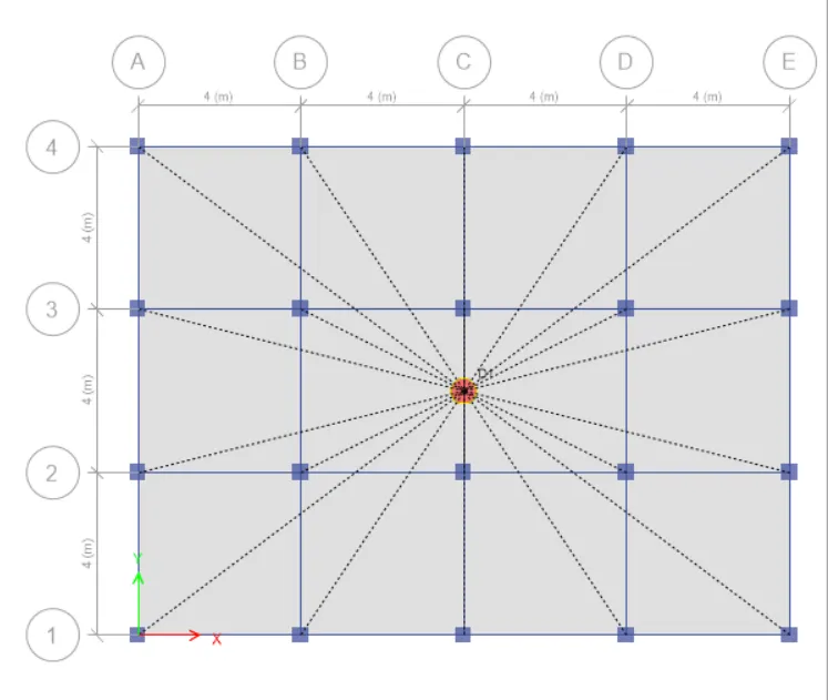
Now run analysis and check it.
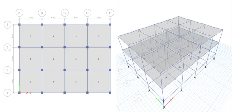
MODEL-B
Now save as Model-A to Model-B and edit.
Every step is same as model-A.
For model-B add 3 edit more storys.
Edit->Edit story and grid system.
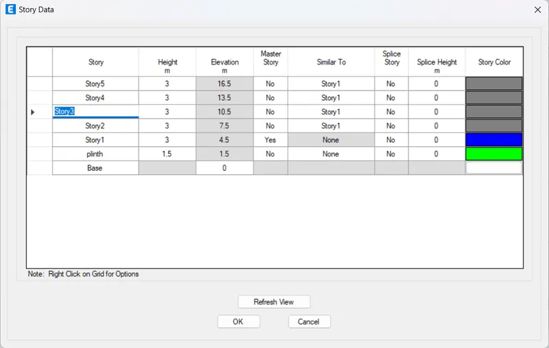
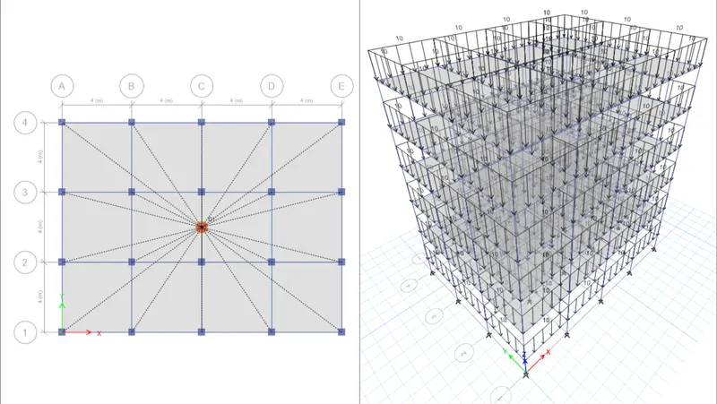
There is no necessary of adding material properties,sections loads to the Etabs as it is select automaticaly as previous model. Now check for floor load and frame load is applied to the model-b, if it is applied then run the analysis.
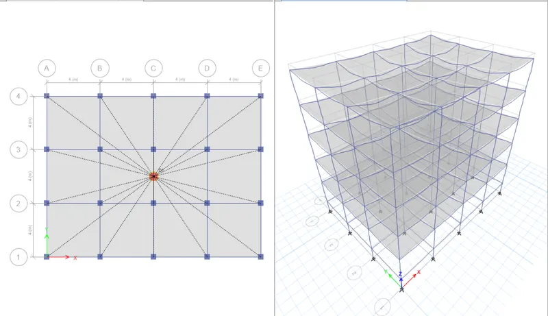
MODEL-C
Now save as Model-A to Model-B and edit.
Every step is same as model-B.
For model-C it need to change column size as 550x300 mm.
To edit column size, Edit->section proerty->frameproperty->select and modify C400x400 into C550x300.
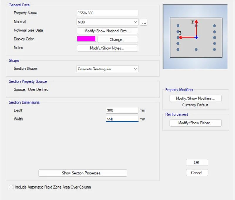
By changing the column size it has to orident column X direction, Select->propeties->frame section ->C550x300, all column in the model is selected.
Assign-> load axes, change degree into 90 all column will rotate.
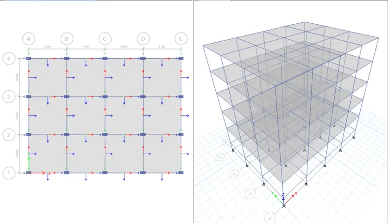
There is no necessary of adding material properties,sections loads to the Etabs as it is select automaticaly as previous model. Now check for floor load and frame load is applied to the model-C, if it is applied then run the analysis.
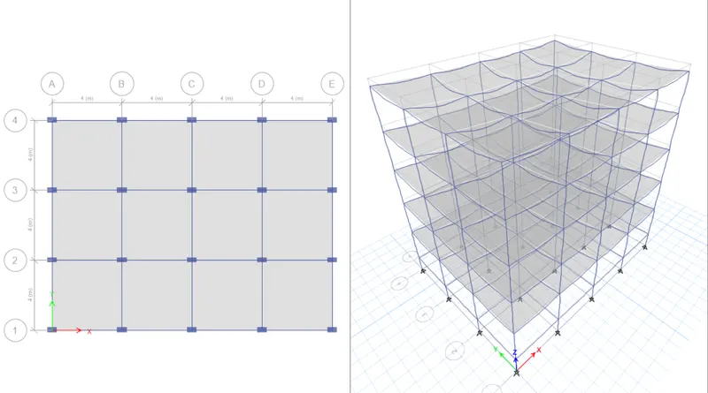
MODEL-D
Now save as Model-A to Model-B and edit.
Every step is same as model-C.
For model-D change the column orientaion to y-direction.
By changing the column size it has to orident column X direction, Select->propeties->frame section ->C550x300, all column in the model is selected.
Assign-> load axes, change degree into 90 all column will rotate.
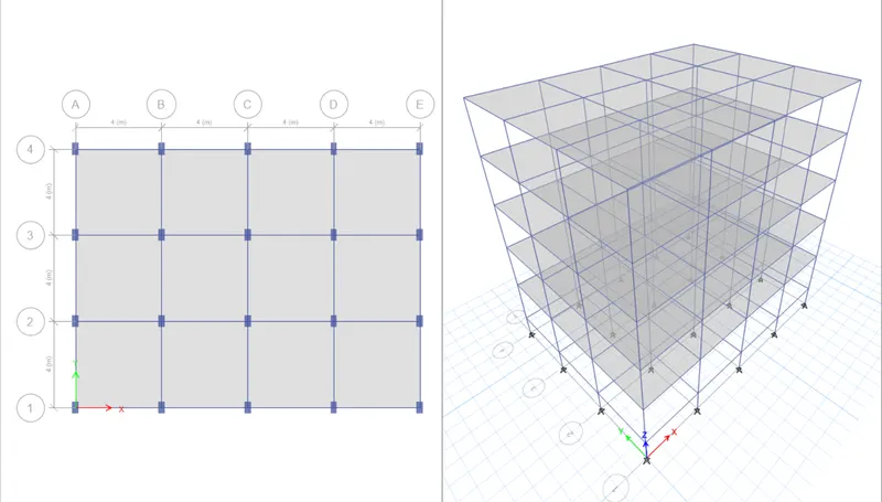
There is no necessary of adding material properties,sections loads to the Etabs as it is select automaticaly as previous model. Now check for floor load and frame load is applied to the model-D, if it is applied then run the analysis.
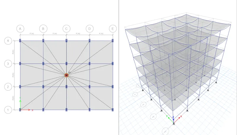
MODEL-E
Now save as Model-D to Model-E and edit.
Every step is same as model-D.
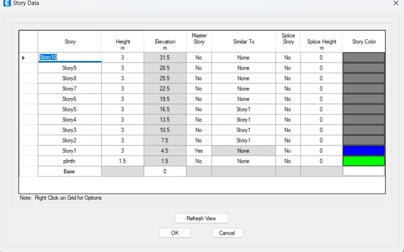
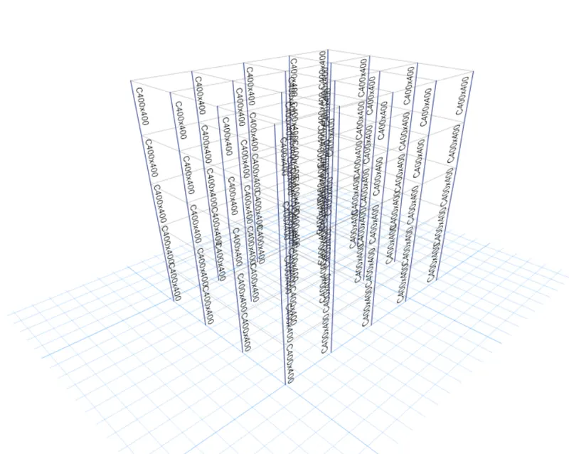
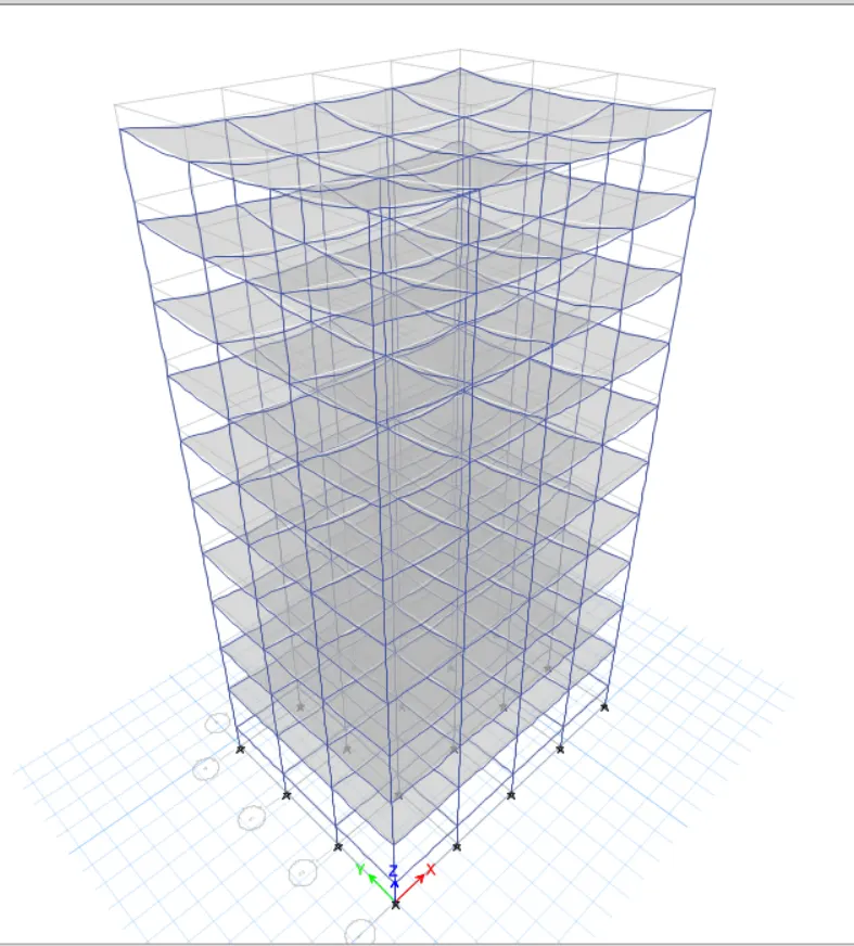
For model-E no of storys is 10
Bottom 5 storys are C600x600
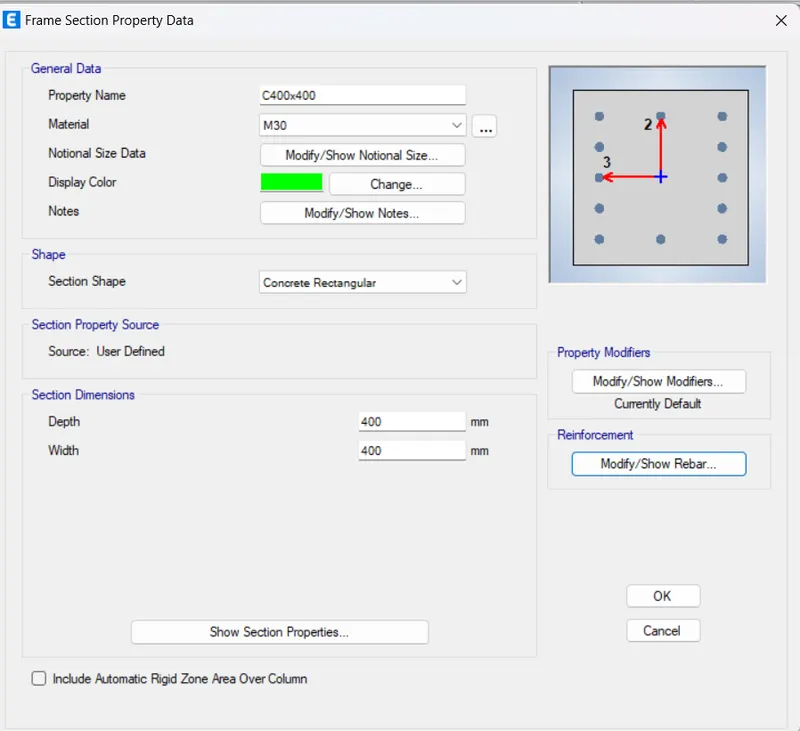
Top 5 storys are C400x400
Edit->Edit story and grid system.
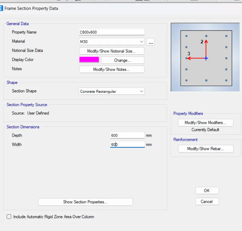
Go to Edit->section proerty->frameproperty->select existing colum and modify into C600x600.
All the 10 story are change into C600x600.
Now add new propert C400x400 for the top 5 storys.
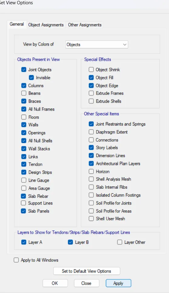
Now click on set display option-> unselect beams & floors, in the model beams and floor is visable.
click on View->Set building view limits-> set story range top story 10story and bottom as 5story.
Select all column->assign->frame->section propert->select C400x400.
There is no necessary of adding material properties,sections loads to the Etabs as it is select automaticaly as previous model. Now check for floor load and frame load is applied to the model-E, if it is applied then run the analysis.
MODEL-F
Now save as Model-E to Model-F.
Every step is same as previous.
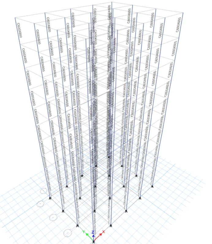
For model-F no of storys is 10 and all column should be C600x600
Select all column->assign->frame->section propert->select C600x600, as all columns are in C600x600
There is no necessary of adding material properties,sections loads to the Etabs as it is select automaticaly as previous model. Now check for floor load and frame load is applied to the model-F, if it is applied then run the analysis.
MODEL-G
Now save as Model-F to Model-G.
Every step is same as previous.
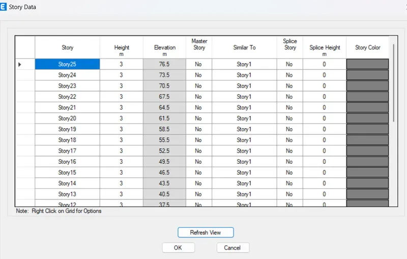
For model-G no of storys is 25.
Top 5 story -C400x400
Middle 10 -C600x600
Bottom 10 story -C800x800
Edit->Edit story and grid system chnge to 25 story.
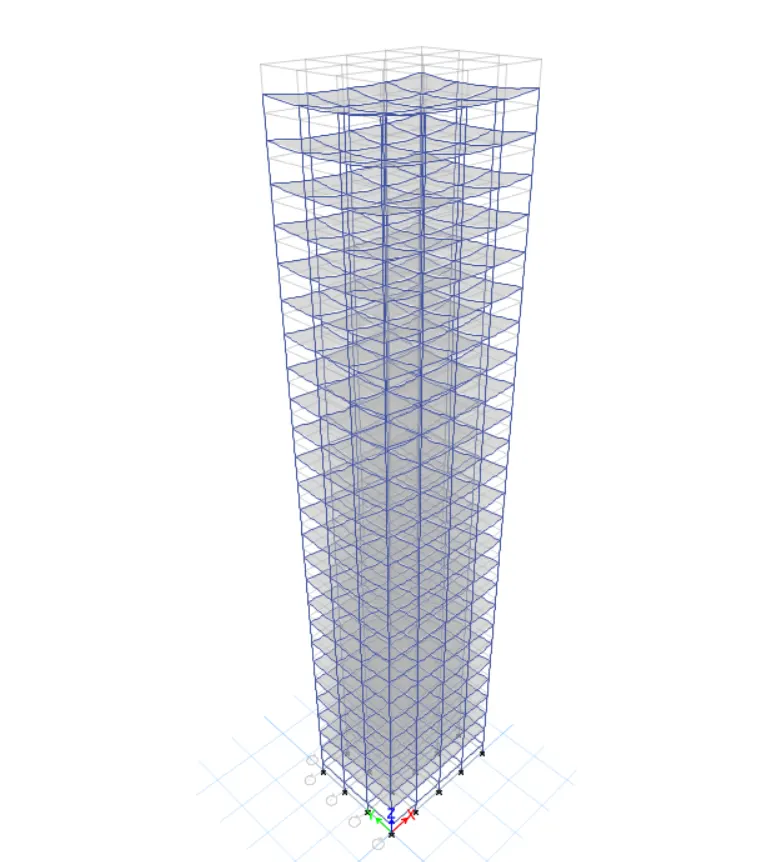
Now click on set display option-> unselect beams & floors, in the model beams and floor is visable.
Go to Edit->section proerty->frameproperty->select existing colum and modify into C800x800mm.
All the 10 story are change into C800x800.
Now add new propert C600x600 for middle 10 story.
C400x400 for the top 5 storys.
click on View->Set building view limits-> set story range top story 25story and bottom as 11story.
Select all column->assign->frame->section propert->select C600x600.
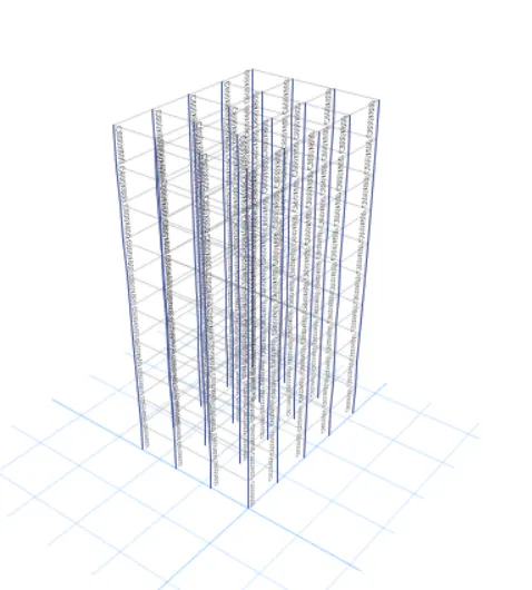
click on View->Set building view limits-> set story range top story 25story and bottom as 21story.
Select all column->assign->frame->section propert->select C400x400.
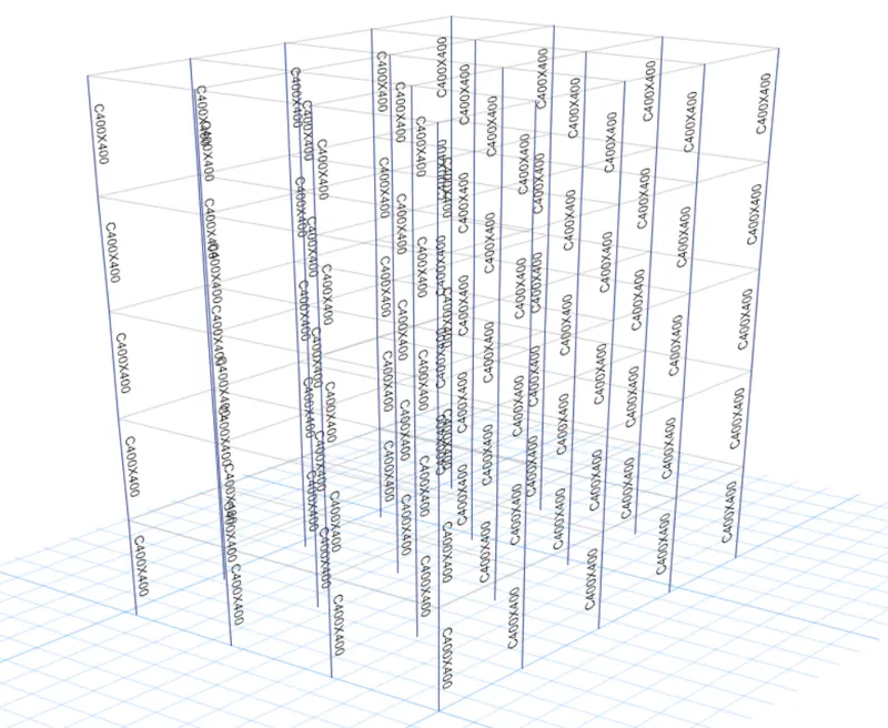
There is no necessary of adding material properties,sections loads to the Etabs as it is select automaticaly as previous model. Now check for floor load and frame load is applied to the model-G, if it is applied then run the analysis.
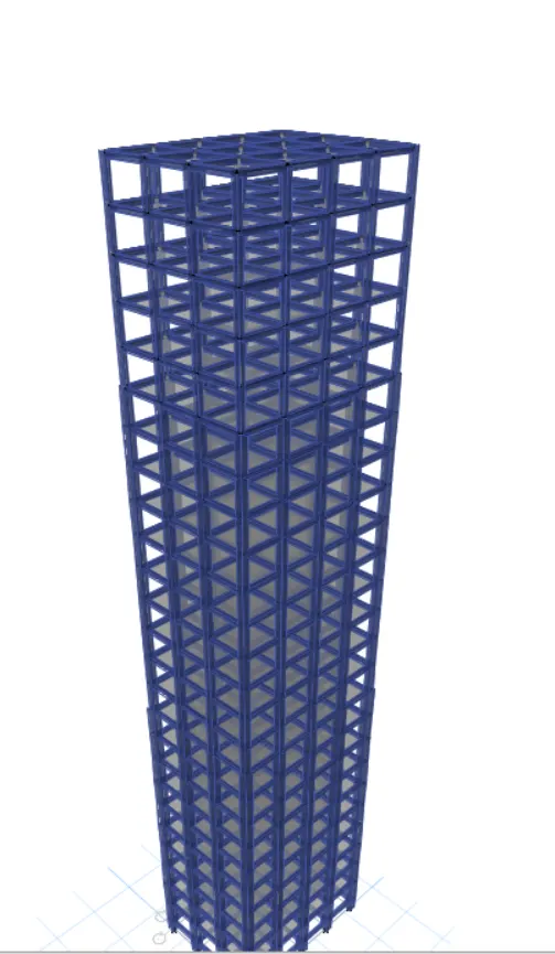
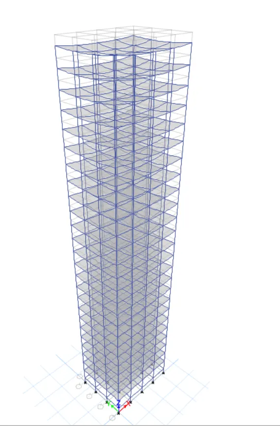
MODEL-H
Now save as Model-F to Model-G.
Every step is same as previous.
For model-G no of storys is 25.
All story columns as C800x800.
Now click on set display option-> unselect beams & floors, in the model beams and floor is visable.
click on View->Set building view limits-> set story range top story 25story and bottom as 21story.
Select all column->assign->frame->section propert->select C800x800.
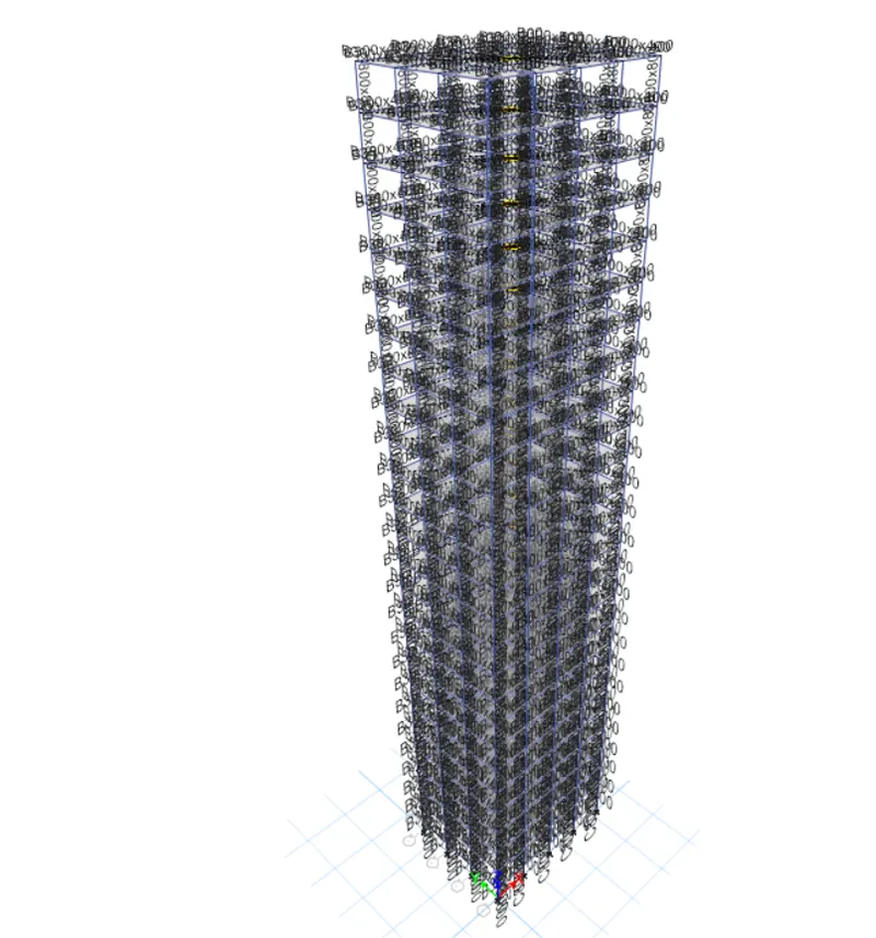
There is no necessary of adding material properties,sections loads to the Etabs as it is select automaticaly as previous model. Now check for floor load and frame load is applied to the model-H, if it is applied then run the analysis.
Model-J
Now save as Model-H to Model-J.
Every step is same as previous.
Imposed load is 10% greater than Model H.
Select->Properties->slab section->S150, all slabs are selected.
Assign->shell load->uniform.
Increse imposed load of 10% as 3.3kN/m2
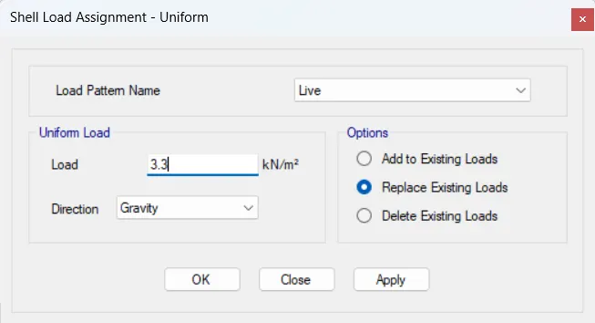
There is no necessary of adding material properties,sections loads to the Etabs as it is select automaticaly as previous model. Now check for floor load and frame load is applied to the model-J, if it is applied then run the analysis.
MODEL-K
Now save as Model-J to Model-K.
Every step is same as previous.
Imposed load is 20% greater than Model H.
Select->Properties->slab section->S150, all slabs are selected.
Assign->shell load->uniform.
Increse imposed load of 20% as 3.6kN/m2
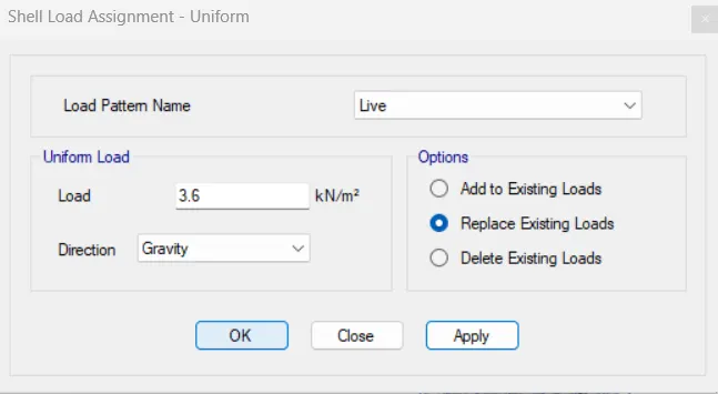
There is no necessary of adding material properties,sections loads to the Etabs as it is select automaticaly as previous model. Now check for floor load and frame load is applied to the model-K, if it is applied then run the analysis.
RESULTS:
- Effect of stiffness on time period on buildings.
| Criteria | Model | Analysis result | Conclusion |
|
Building-E (10 storeys with varying column sizes) |
1.73 s | For low-rise buildings, changing the column size does not have much effect on the time period of the building. As you see in the analysis result, the time period is nearly the same. |
|
Building-F (10 storeys with uniform column sizes) |
1.73 s | ||
|
Building-G (25 storeys with varying column sizes) |
4.17 s | For High-rise buildings, changing the column size has many effects on the time period of the building. As you see in the analysis result, the time period of the two buildings has much different. |
|
Building-H (25 storeys with uniform column sizes) |
4.41 s | And buildings with varying column sizes are more stable than uniform column sizes. as less mass is lumped in buildings, which leads to less lateral displacement. |
- Effect of mass on time period on buildings.
| Criteria | Model | Analysis result | Conclusion |
|
Building-H (25 storeys with 3KN/m2 imposed load) |
4.41 sec |
As we know, as imposed load increases, the time period of the building will also increase. Here, we see that there is no significant increase in the time period even though an increase in the load of the building. Because |
|
Building-J (25 storeys with 3.3KN/m2 imposed load) |
4.42 sec | Because imposed load is distributed in the building uniformly. | |
|
Building-K (25 storeys with 3.6KN/m2 imposed load) |
4.43 sec |
- Effect of building height on time period on buildings.
| Criteria | Model | Analysis result | Conclusion |
|
Building-A ( 2 storeys building) |
0.5 sec | As per IS 1893: 2016we know the time period is directly proportional to the height of the building so we clearly see from the analysis result that the time period of buildings increases as the height of buildings increases. |
|
Building-B (5 storeys building) |
1.03 sec | ||
|
Building-F (10 storeys building) |
1.73 sec | ||
|
Building-H (25 storeys building) |
4.41 sec |
- Effect of column orientation on time period on buildings.
| Criteria | Model | Analysis result | Conclusion |
|
Building-B ( column 400x400) |
1.1 sec - x direction 1.036 sec- y direction |
As column size is the same in both X and Y directions, there is not much difference in their time period. As stiffness is the same in both directions. |
|
Building-C ( column 550x300) |
0.926 sec - x direction 1.145 sec- y direction |
As column size is the not same in both X and Y directions, there is much difference in their time period. As stiffness is not the same in both directions. | |
|
Building-D (column 300x550) |
1.12 sec - x direction 0.953 sec- y direction |
In building c, deformation is more in the Y direction compared to the X direction and vice versa. |
- Effect of Flexural Stiffness of Structural Elements on mode shapes
| Criteria | Model | Analysis result | Conclusion |
|
Building-B (Flexural stiffness of beams close to zero takes 10% of it.) |
2.627 sec | As we see from the analysis result, the time period of the building is increased by approximately double. So the building is unstable. |
|
Building-B ( full flexural stiffness of beams) |
1.036 sec |
- Effect of Axial Stiffness of Vertical Members on mode shapes
| Criteria | Model | Analysis result | Conclusion |
|
Building-H (Axial stiffness of column close to zero takes 10% of it.) |
5.991 sec | As we see from the analysis result, the time period of the building is increased. So the building is unstable. |
|
Building-H ( full axial stiffness of columns) |
4.416 sec |
- Effect of Degree of Fixity at column bases on mode shape
| Criteria | Model | Analysis result | Conclusion |
|
Building-B (pinned) |
1.036 sec | As we see from the analysis result, the time period of the building is decreased. As we know as per IScode 1893:2016, fixed support has more stiffness than pinned support. so the time period is decreased. |
|
Building-B ( fixed base) |
0.941 sec |