Project 1_Comparative study of different storey buildings for Seismic forces
PROJECT
Comparative study of different story buildings for seismic forces
Aim: To model and analyze multiple buildings with different floor levels and design parameters using ETABS software and compare the results to understand their overall seismic behavior.
Introduction:
A building's structural geometry plays an important role in determining its overall response during an earthquake. Different building geometries behave differently when induced by the same seismic force. Therefore, a correct understanding of a building's response to structural configurations is critical for a safer design approach. Therefore, in this project, ETABS was used to model different buildings with different shapes. Furthermore, by analyzing the answers with software and comparing the results, it is possible to understand the structural behavior of buildings with different numbers of floors.
Procedure:
For ease of approach, the project is divided into two phases. The first phase covered the modeling part of the building. Here structures are drawn from scratch according to specified geometric and structural conditions. Additionally, the first phase itself runs the analysis and generates structural output for all buildings. In addition, the second phase of this project will involve a comparative analysis of the structural results obtained in the first half. Also, based on the comparison results, different structural characteristics of the building are inferred in terms of seismic response.
Phase 1: Model buildings and generate respective structural outputs using ETABS
- Building “a” (G+2)
- Open ETABS from the shortcut on your desktop or by searching for it in the Start menu.
- Once the software is up and running, click on the New Model option.
- Clicking on the new model will bring up a dialog box where you can set the code and units used in your project.
- Make the necessary settings and click OK to start modeling the first building in this project.
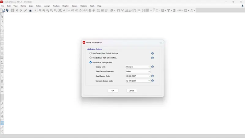
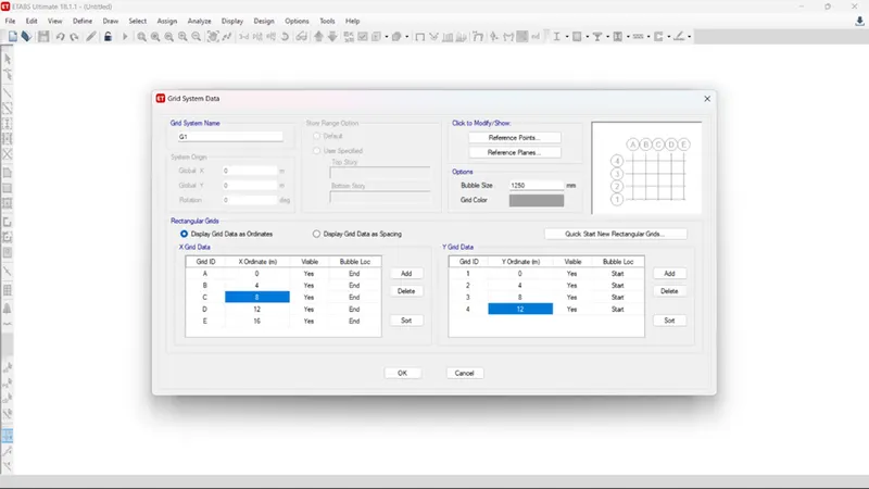
- To set the grid data you need to click on the custom grid option.
- When done, a menu with all grid settings will open.
- In the same menu you can set the length, the number of grids in both orthogonal directions, the distance between all vertical and horizontal grids, etc.
- Similarly, set a 4x3 field grid with 4m centers.
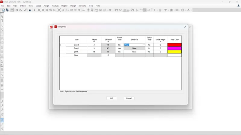
- Click on the custom story data option as well as the grid settings.
- Next, specify the base level, base level, height of each floor, and number of floors to include in the model.
- We therefore placed a G+2 building with a height of 1.5 m from the base.
- You must also repair all similar floors within the same menu as the main floor.
- And in our project floor 1 is the master and all the remaining floors are similar.
- Once this is done, the model will run in ETABS with the specified grid and floor.
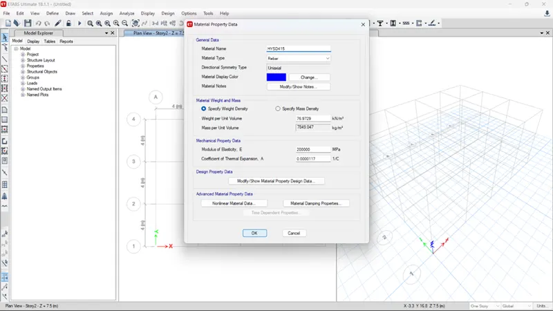
- It is important to specify the ETABS details for the materials used in the project.
- Also in this model, according to specifications he must use M30 grade concrete and HYSD steel Fe415.
- To define the same go to Define > Materials > Properties > Add New > Concrete/Steel > Grades > OK.
- However, since we have already specified the Indian Standard Code of Practice, M30 concrete and 450 steel will be included in the project by default.
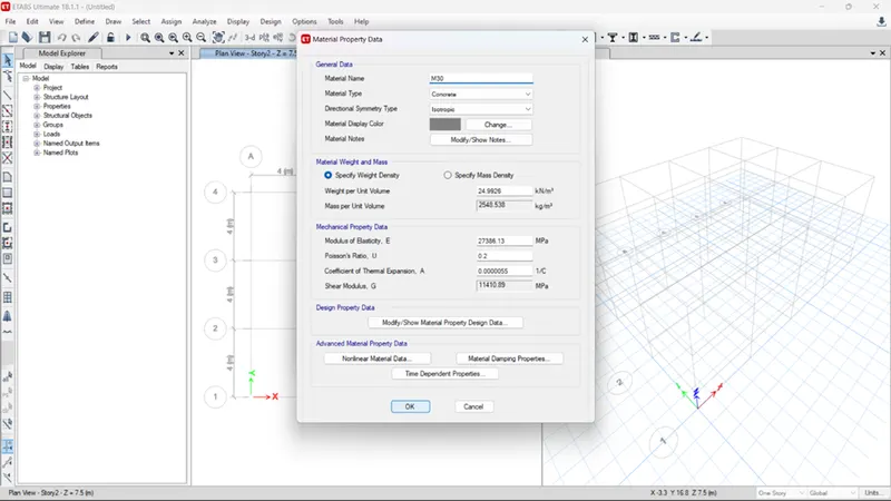
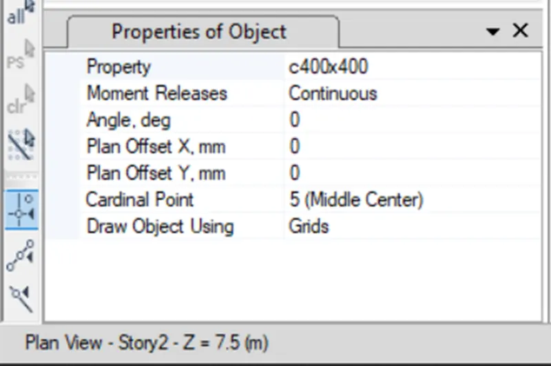
- Use rectangular concrete sections for all structural elements such as beams, columns, and slabs.
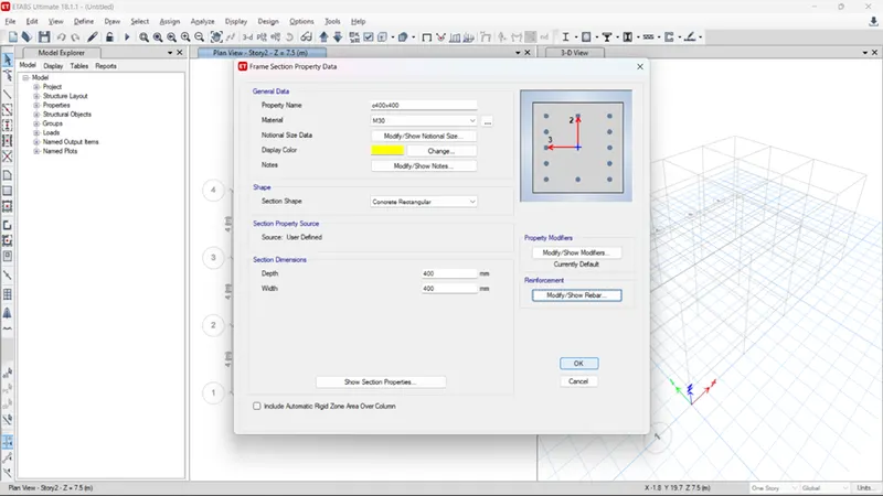
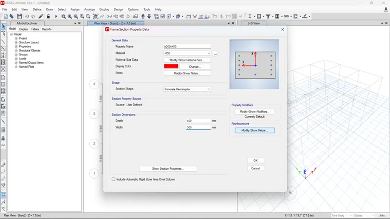
- Therefore, it is necessary to define this in the ETABS software so that these sections can be used repeatedly throughout the project.
- Go to Define > Material Properties > Frame sections > Concrete Rectangle.
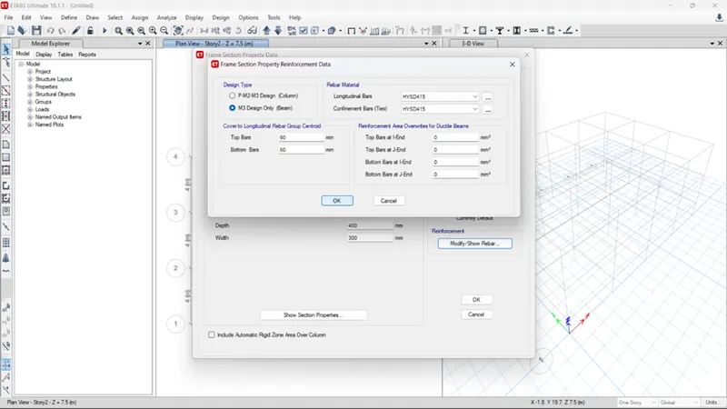
- The ETABS screen then displays a dialog box where you can specify the column/beam dimensions and the type of rebar (HYSD415) to be used in the model.
- So, you can define both columns and beams from the same menu.
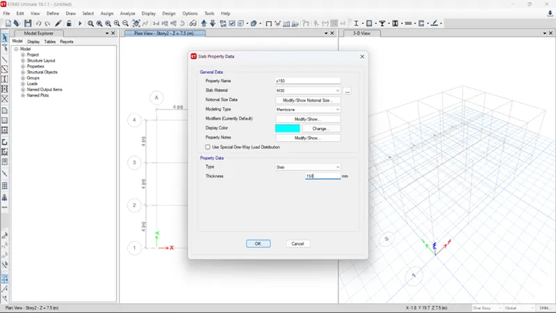
- To define the slab section, go to Define > Sections > Slabs again.
- Reopens the menu where you must specify the plate specifications required for your project.
- Here we need to specify the plate thickness as 150 mm and the cross section as membrane.
- Now that we have defined everything from materials to beams, columns, and slabs to be needed for our structure, we can go ahead and draw each structural element as per the specifications.
- And to do that, we can use the commands in ETABS named quick draw tool.
- As the name suggests, you can draw all the beams, floors, and columns with the help of this tool.
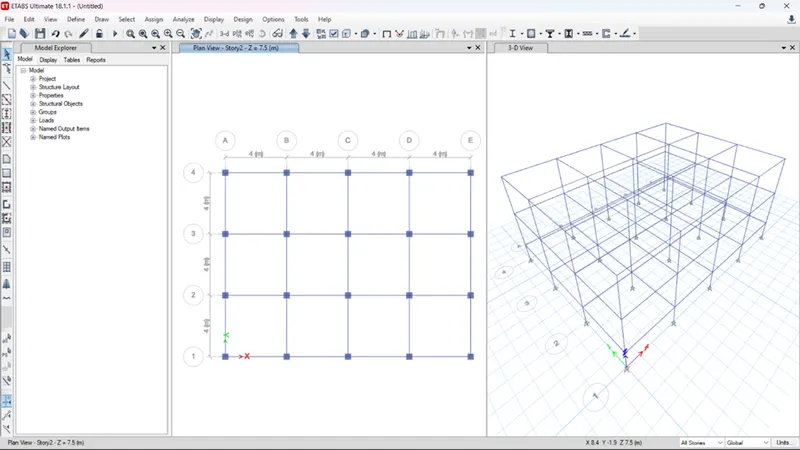
- All you need to do is select the relative tool that is quick draw columns for drawing columns and vice versa. Then choose the section from the dropdown list.
- Then, simply go to the grid system in plan view and start clicking on the grid locations where you want to build these structural elements.
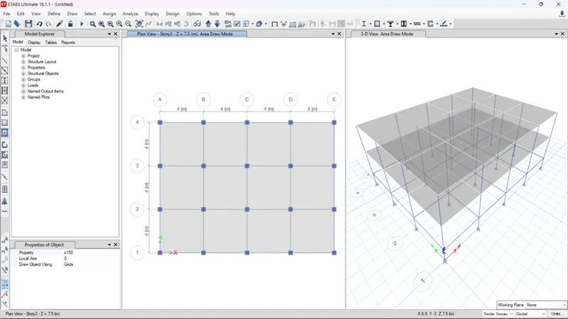
- So, the same approach was followed and the following beams, floors, and slabs were drawn in our ETABS model.
- Once the model is complete, it should list the types of loads expected during the life of the structure.
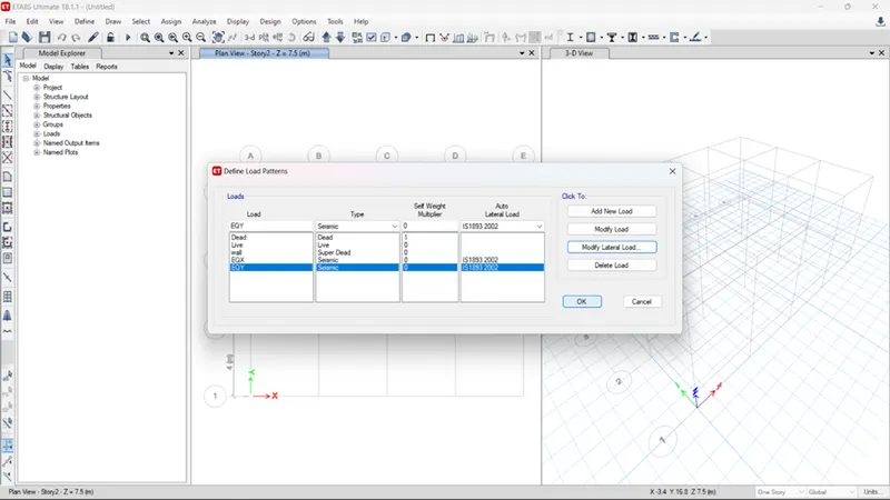
- Go to Define > Load pattern > Add load.
- All loads can be added here. In our project we have fixed loads, super fixed loads (brick wall loads), live loads and seismic loads in the x and y directions.
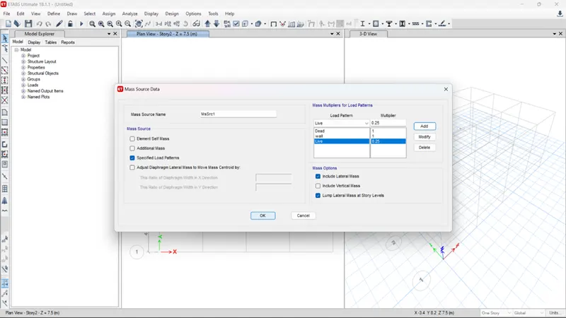
- You must also define the mass source by adding 100% of deadweight and super deadweight and 25% of payload or payload.
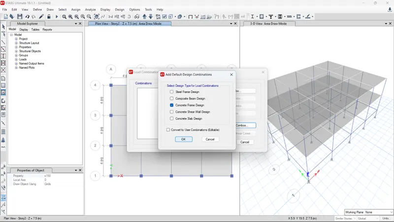
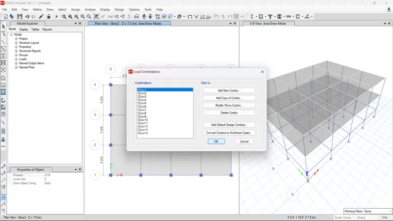
- Define > Load Combinations > Default Combinations > Check the Convertible option.
- A list of load combinations is displayed. This can be viewed and changed as needed at any time during the project.
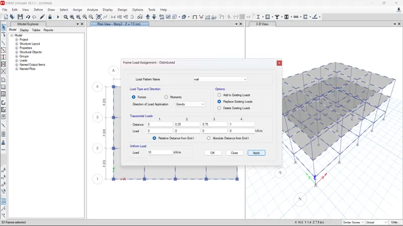
- You can select specific structures from your model and assign loads to them.
- For example, select a beam and assign a Super Self Weight UDL to it because there is a brick wall above it.
- Therefore, a similar method is used, and the beam and slab loads are assigned as follows:
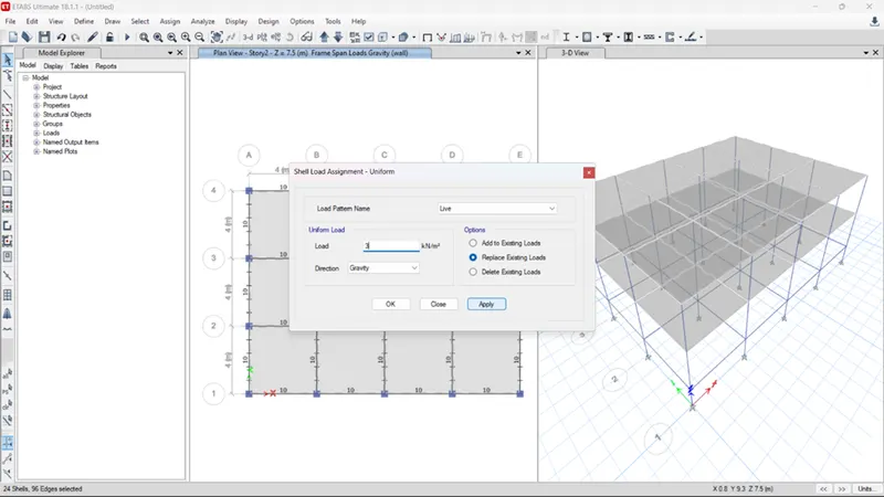
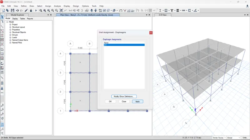
- Select plate section S150 from the selection options. Go to
- Assign>shell>Membrane. Select the standard D1 aperture already built into the
- ETABS and press OK.
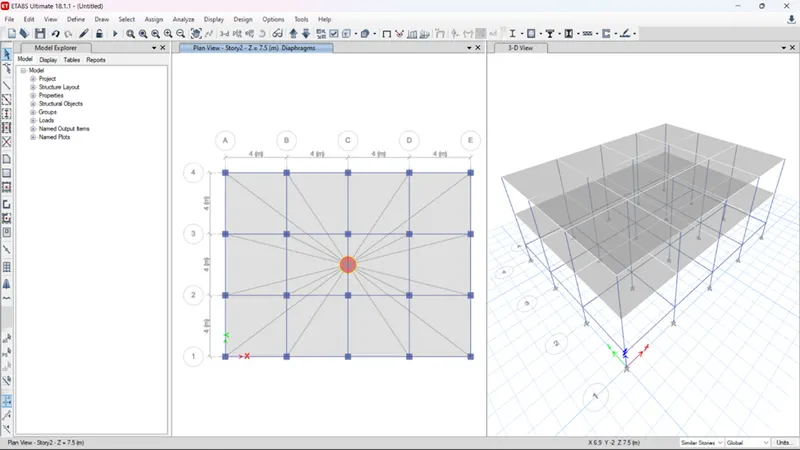
- You're done! You can see that the center of gravity of the model was automatically calculated when you assigned the floor membrane.
- Now that everything about the first model is done, we can proceed with the analysis of this building.
- However, the project must be saved before the analysis can be performed, so save it to a suitable location in your system.
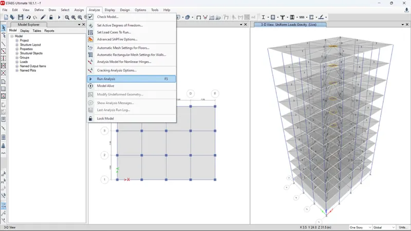
- Next, press F5 on your keyboard or click the arrow on the ETABS screen to run the analysis of the current model.
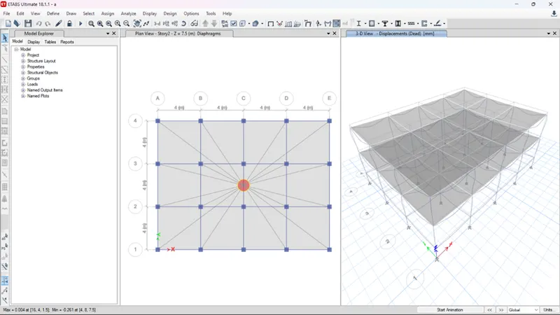
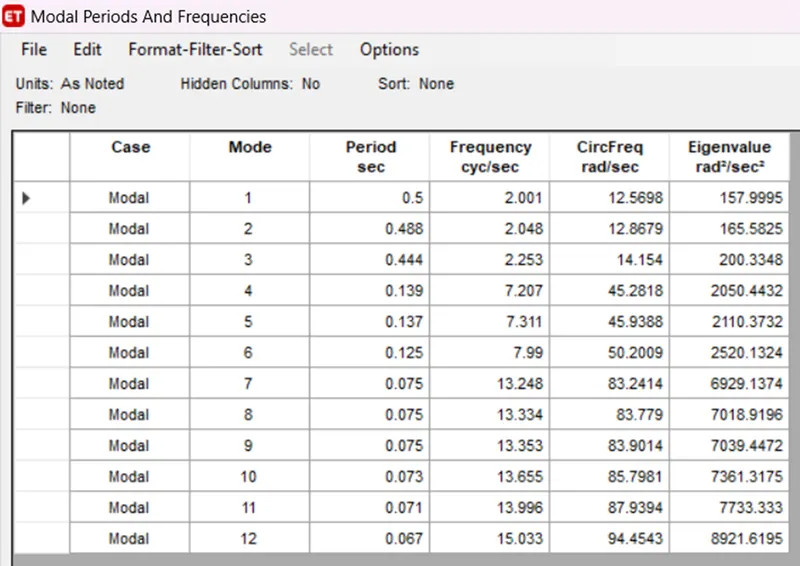
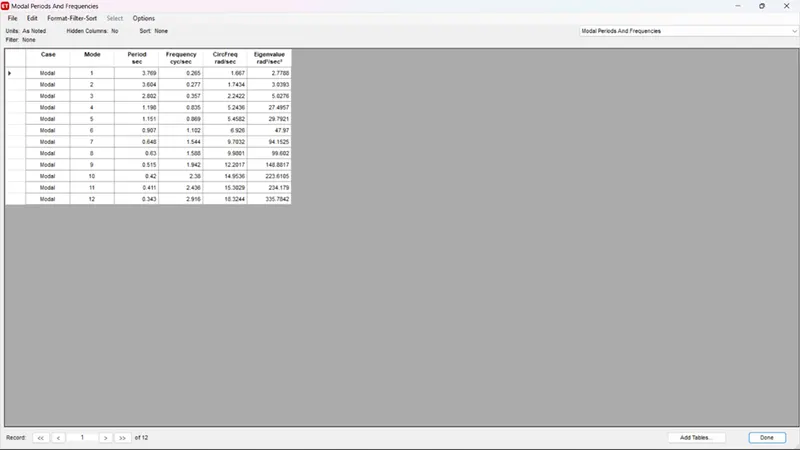
- Modal response for building “a”
- Building “b” (g+5)
For model B, there is no need to create a new ETABS file from scratch. Instead, save a copy of Building A's file and make the necessary changes to Building B. For example, you can increase the number of floors to 5 by editing the floor data in the copied file. The complete steps to do this in ETABS are described below.
- From Model A, go to File and click the Save As option.
- Specify the destination folder and name it "BUILDING B".
- The model is set to change according to the requirements of building b
- In your new file, go to Edit > Story and Grid Data.
- Click the Change Story Data option.
- Now right-click on the top floor and select Add Floor.
- Specifies the number of floors and height to add.
- In this case, to convert a 2-story building into a 5-story building, you need to add 3 more floors.
- Also make sure that each story is similar to the master story created in Model A.
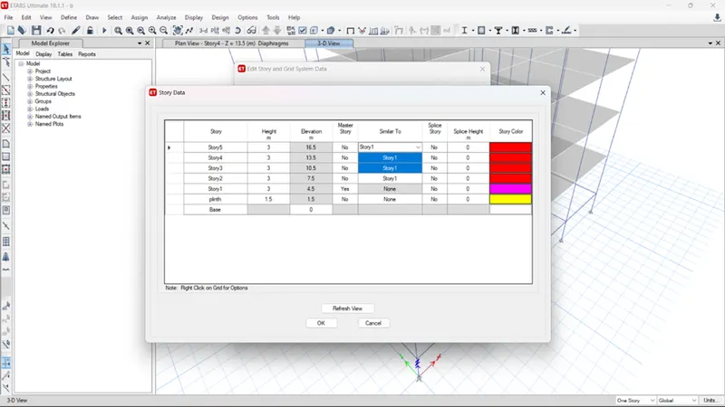
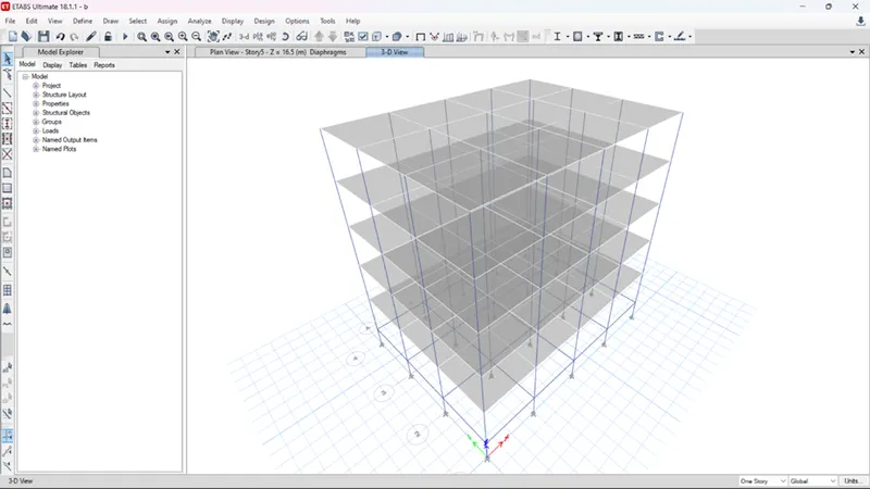
- Now that our model is ready we need to check for two to three things before running the analysis and noting the modal period.
- The first check is for the load assignment.
- From the bottom ribbon in ETABS, go the show frame and shell loads one at a time.
- This way the model will show if the corresponding load has been assigned till the top floor.
- Similarly, you need to check if the diaphragm has been assigned to the new model or not.
- You can check it by going to the view settings option and checking the diaphragm visibility.
- If the diaphragm is not visible, you need to select all the floors and assign the diaphragm like we did for the first model
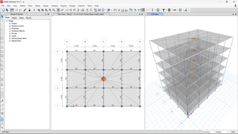
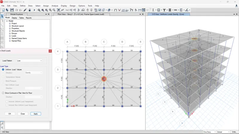
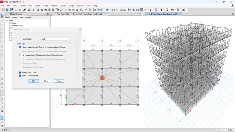
- After all the checks are done and the structure is in place, the analysis can be done.
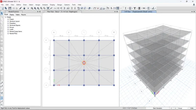
- To do this press her F5 key on the keyboard or click the arrow in the ribbon under ETABS.
- It takes a few seconds before the curve of the building appears indicating that the analysis is complete.
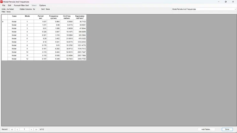
- Building “c”(g+5) with column orientation in X-direction.
Building c's floors and grid data are unchanged. However, I need to resize the columns and align them in the X direction. Therefore, the complete step-by-step instructions for the same are detailed below.
- Choose a suitable location and save the file as Building C.
- The model is now set up for editing as required.
- To edit the column section, go to Define > Section Properties > Frame Section.
- Now select the columns for buildings A and B created earlier.
- Click the Change/View Properties option.
- Rename columns as needed. In this case it is 550x300.
- Then edit the length and width by entering values in the boxes.
- Next we need to align 550mm in the X direction. For
- , select the column section and go to Assign > Local Axis > Rotation > 90 degrees.
- All supports should be oriented in the X direction like this. So 550 mm is in the X direction.
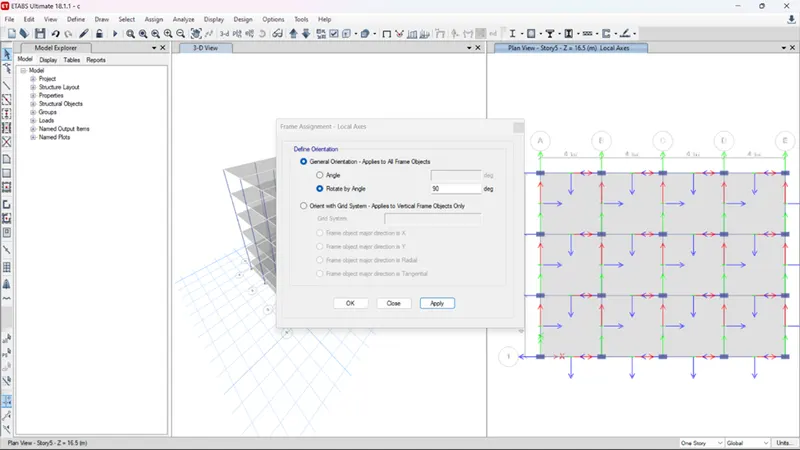
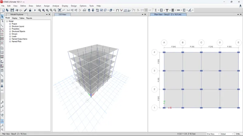
- As with building B, the frame and shell loads should also be checked here.
- Also make sure the soil film is assigned before proceeding with the analysis.
- Press F5 on your keyboard and ETABS will automatically perform the analysis.
- Once the analysis is complete and the curved shape of the model is displayed on screen, the modal table can be viewed.
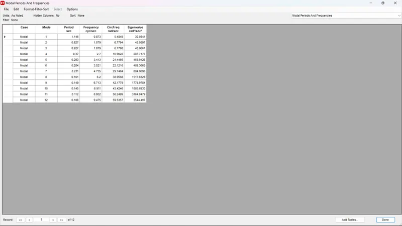
- Building “d” with column orientation in y-direction
You don't need to change anything in this model other than column placement. The column size remains the same, but the column alignment needs to be moved from the X direction to the Y direction. So just like the previous model, save the D file as a C file. Then select the column section, assign a local axis, and set the origin back to 0. This way all the columns should be aligned in the Y direction. Then, as usual, check the loads and diaphragms before running the analysis. Next, note the modal period of building D.
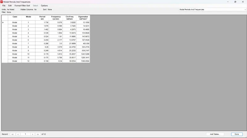
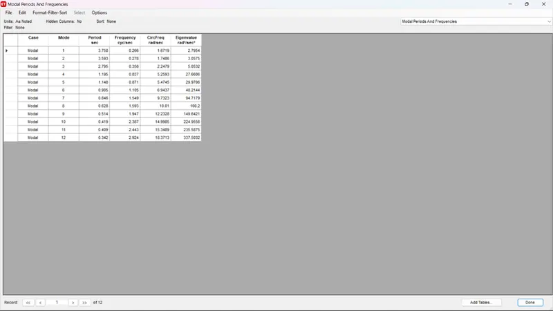
Therefore, as explained above, a model of building D was run and the natural period was recorded as inserted below.
- Building “e” (g+10) witch column for top 5 stories of 400x400 and bottom 5 stories of 600x600.
For this model, we need to add 5 more floors to the model. In addition, we also need to assign different column sizes for each floor. To do so, first save the ETABS file for building D as a new model for building E. Then edit the floor data in ETABS as you did in the previous model. Next, we need to add two new column sections with the required orientation and assign them to the corresponding floors in the model as shown.
Below are step-by-step instructions for creating new columns and placing them on the desired floor.
- Add up 5 New Stories and Set the Model for Building E
- Set storey 5 as a master storey.
- Set the storey from plinth to storey 4 similar to storey 5.
- Do the same for the top 5 floors by making the 10th floor as master storey and setting 6 to 9th storey similar to it.
- Now define section properties and add 2 new column properties for sizes 400x400 and 600x600 respectively.
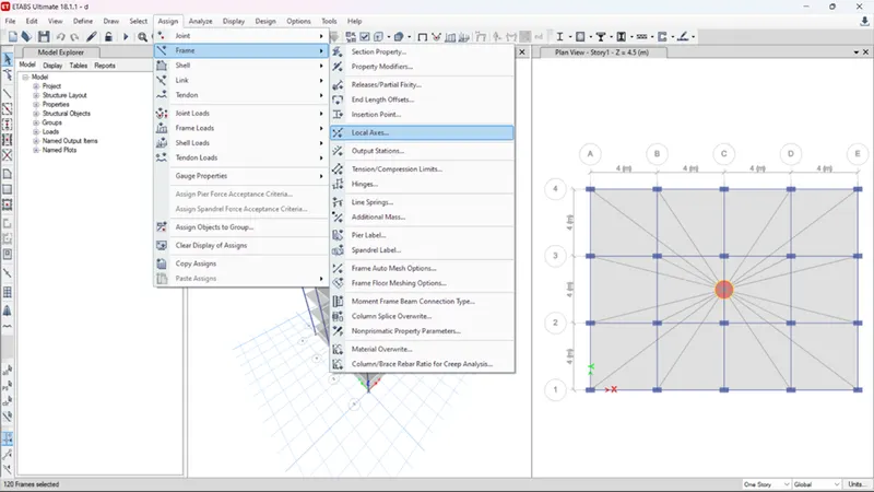
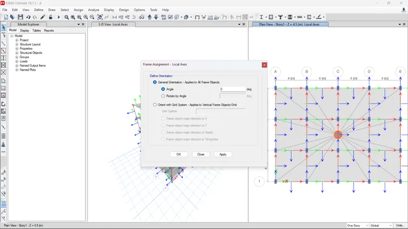
- Now open the storey 5 plan and set the changes to similar stories only.
- Select the columns using the select>object type>columns
- Then go to assign>c600x600 and click on apply.
- Repeat the same process to apply the c400x400 columns to the top 5 stories.
- Now check the assigned frame and shell load before analyzing the structure.
- Start the analysis and record the modal response.
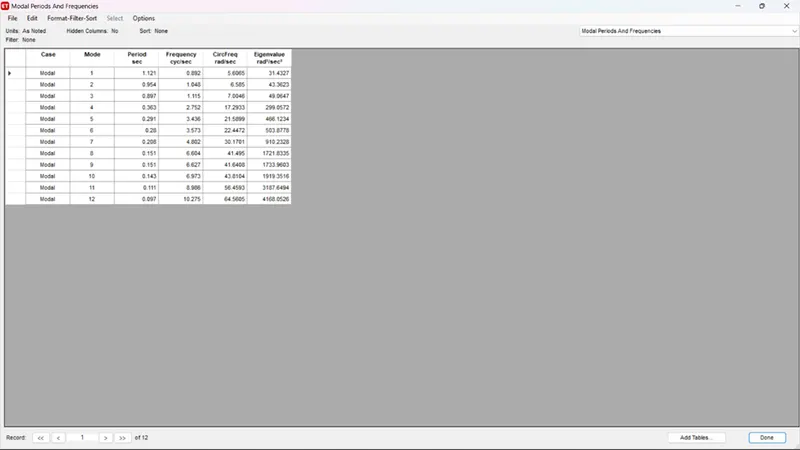
- Building “f” (g+10) with column size throughout the structure: c600x600
The building uses the same columns throughout the structure. Therefore, you don't need to edit much when it comes to sections. Adjust the view settings, hide beams and floors, select all columns, and assign a frame profile property of C600x600.
- Select all columns using select>object type>columns.
- Go to assign>frame>section properties>c600x600.
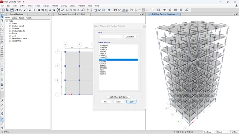
- Click apply.
- Analyze the model.
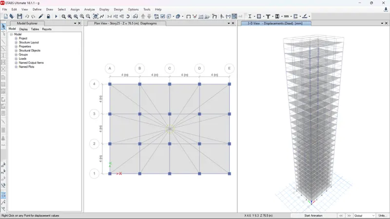
- Building “g” (g+25) with columns of bottom 10 stories c800x800, middle 10 stories c600x600 and top 5 stories c400x400.
- Edit story data and add 15 new stories
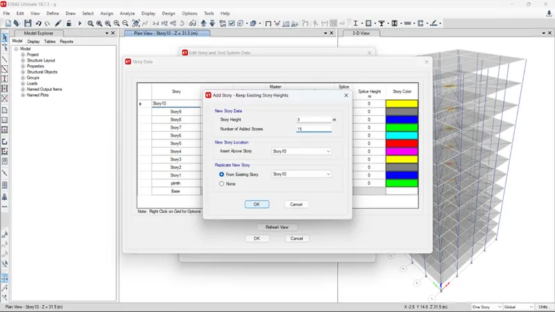
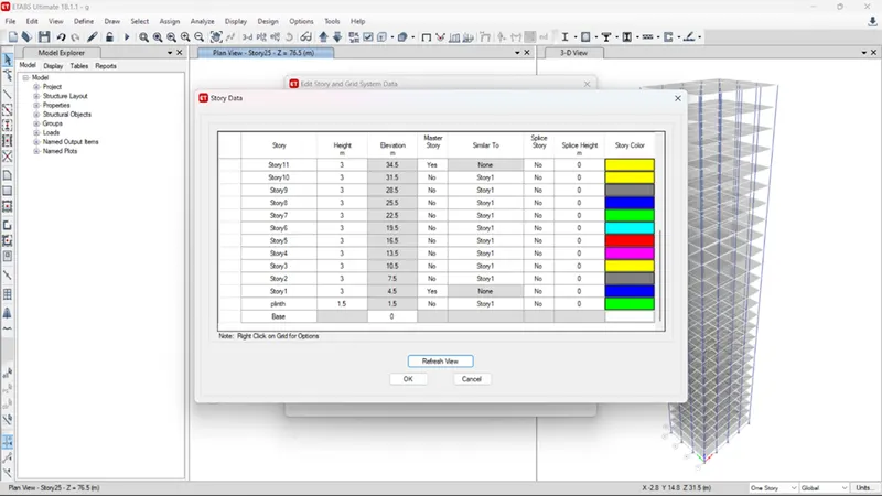
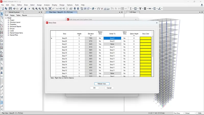
- As shown above set floors 10,20 & 25 as master floors and set floors the intermediate floors similar to them.
- Now go to the 10th
- Click on quick draw columns.
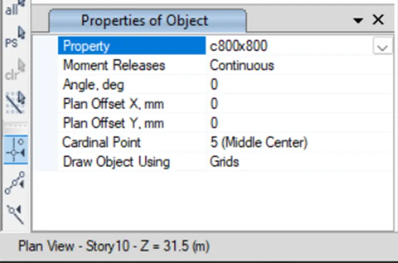
- Select c800x800 and click on the nodes to draw the columns from floor 10 to the base.
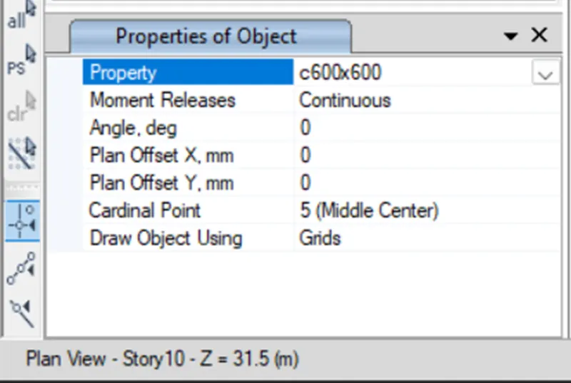
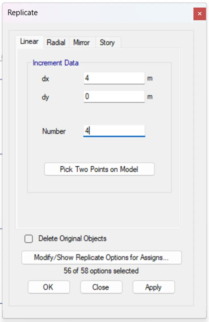
- Similarly go the 20th floor and select the c600x600 columns and quick draw them by clicking on the peripheral nodes and using replicate to spread them throughout.
- Repeat the same process by going to the 25th floor and drawing the c400x400 columns there.
- Now check for the assigned frames and shell loads by using the display option and checking the diaphragm assignment using the view>set display options> check diaphragm extents.
- Run the analysis.
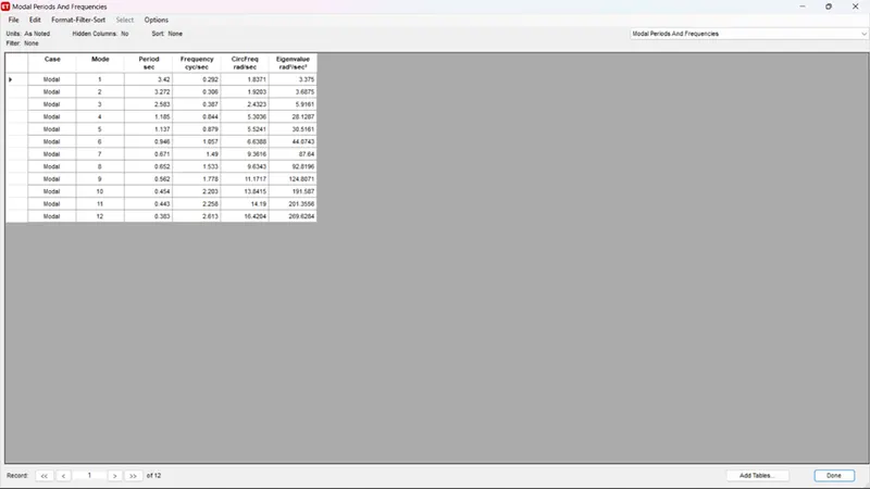
- Building “h” (g+25) with consistent column size throughout the building i.e., c800x800.
This is the same model as the previous model. All you have to do is assign the column section as C800x800 for the entire structure. This is done by selecting all columns, going to Allocation, selecting C800x800 and clicking OK. So, for better understanding, the same steps are given below.
- Select the columns using select>object type>column.
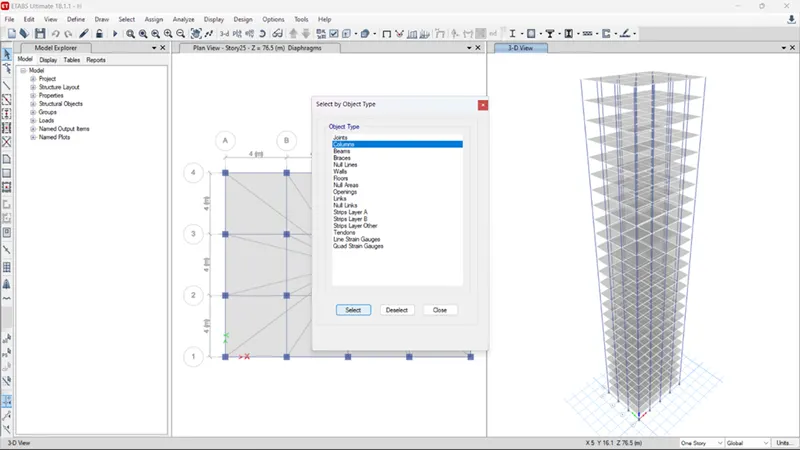
- Got to assign>frame>section properties>c800x800.
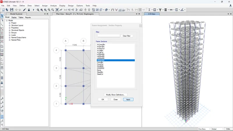
- Apply the column property to all the selected columns by clicking on apply.
- Now all the assigned loads.
- Run the analysis.
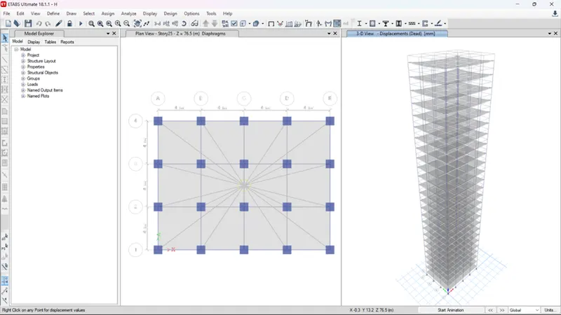
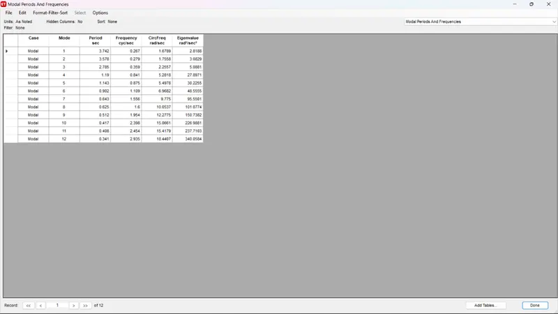
- Building “j” (g+25) with 10% increment in the imposed loads.
Building J is an exact copy of model H and you don't need to change anything in your modeling. However, we need to increase the load on the building by 10%. This is assigned as 3 KN/m^2 for all panels of the building. Here are the steps to do the same.
- Select s150 slab section
- Go to assign>shell loads>uniform>change the live load value from 3 to 3.3.
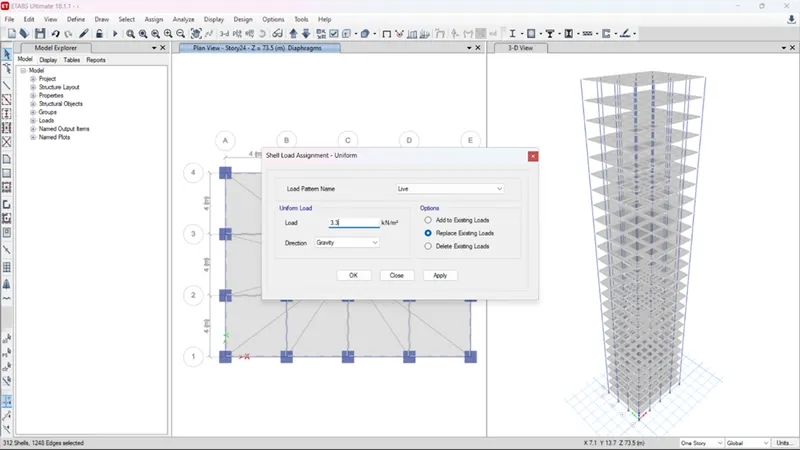
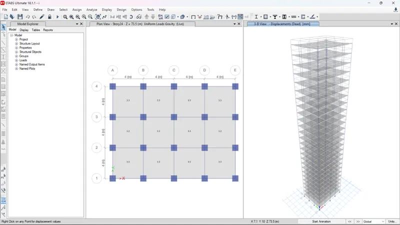
- Click on apply.
- Run the analysis.
- Building “k”(g+25) with imposed loads 20% more than that of building “h”.
In this model, we can proceed in the same way as when constructing j. However, this time we need to increase the payload by 20% instead of 10%. So here are the step-by-step instructions.
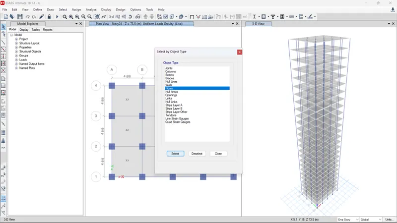
- Go to select>object type>floors.
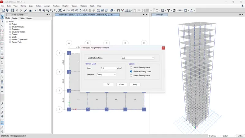
- Go to assign>shell loads>uniform>change the live load value from 3 to 3.6 and apply.
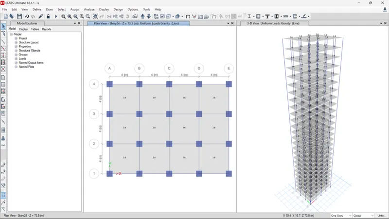
- Run the analysis.
Phase II: Comparative Analysis of Building Real Estate with Structural Results
Having completed the modeling and analysis of buildings with different floors in the previous phases of this project, we will compare these results and try to understand the changes in building behavior based on structural geometry. Therefore, in the next section, we perform a comprehensive comparative analysis of the static properties of buildings with different floors using different criteria such as stiffness, mass and building height.
- Effect of stiffness on T: Compare fundamental natural periods of buildings E & F as well as G & H. Why is there a marginal or significant difference in the fundamental natural periods?
|
Model name |
No. of storey |
Column design specification |
Natural period (Seconds) |
|
Building e |
10 |
Upper 5 storey:400x400 |
1.732 |
|
Bottom 5 storey:600x600 |
|||
|
Building f |
10 |
Consistent column size throughout: 600x600 |
1.736 |
|
Building g |
25 |
Upper 5 storey:400x400 |
4.386 |
|
Middle 10 storey:600x600 |
|||
|
Lower 10 storey:800x800 |
|||
|
Building h |
25 |
Consistent column size throughout: 800x800 |
4.614 |
Building E and Building F are five stories tall, so the design of the pillars is not much different. However, you can see that in buildings G and H, the column sizes are constant throughout the structure, creating a more natural periodicity. Therefore, we can conclude that to control the natural period 'T' of a tall building, place a large column at the bottom and a smaller size at the top floor.
- Effect of mass on T: Compare fundamental natural periods of buildings H, J and K. Have the buildings become more flexible or stiff due to change in mass?
|
Model name |
No. of storey |
Percentage increase in mass |
Natural period (seconds) |
|
Building h |
25 |
Regular with no mass increment |
4.614 |
|
Building j |
25 |
10% mass increment |
4.626 |
|
Building l |
25 |
20% mass increment |
4.636 |
As can be seen from the table, the natural period of a tall building is directly proportional to the mass imposed on the building.
- Effect of Building Height on T: How do the fundamental natural periods of Buildings A, B, F, and H change with a change in building height?
|
Model Name |
No. of stories |
Total building height (m) |
Natural period (seconds) |
|
Building a |
2 |
7.5 |
0.5 |
|
Building b |
5 |
16.5 |
1.036 |
|
Building f |
10 |
31.5 |
1.735 |
|
Building h |
25 |
76.5 |
4.614 |
As shown in the table above, the natural period "T" is also directly proportional to the height of the building.
- Effect of Column Orientation on T: How do the fundamental natural periods of Buildings B, C, and D change with a change in column orientation?
|
Model Name |
No. Of Stories |
Column Orientation |
Natural period (seconds) |
|
|
Building b |
5 |
Equal in both directions |
9.48 |
9.75 |
|
Building c |
5 |
x-direction |
8.72 |
10.82 |
|
Building d |
5 |
y-direction |
10.5 |
9.01 |
If the column has a square cross-section, there is not much difference in lateral displacement in the two orthogonal directions. However, if you orient the column in a particular direction (X or Y), the lateral displacement in that particular direction will be less than in other directions with shorter column lengths.
- Effect of Flexural Stiffness of Structural Elements on mode shapes: Compare fundamental mode shape of Building B in two situations when the flexural stiffness of beams relative to that of adjoining columns is very small versus when it is large.
|
Model Name |
Flexural stiffness of beams |
Natural period |
|
Building B |
100% |
1.036 |
|
10% |
2.627 |
It is clear that reducing the bending stiffness of the beam also reduces the overall bending strength of the beam, resulting in an increase in the natural fundamental period.
- Effect of Degree of Fixity at column bases on mode shape: Compare the fundamental mode shape of Building B in two situations when the base of columns is pinned versus when it is fixed.
|
Model Name |
No. Of Storey |
Base Support |
Natural period |
|
Building b |
5 |
Pinned |
1.036 |
|
Fixed |
0.941 |
It is clear that fixed supports are less restrictive than fixed supports, resulting in more movement and thus increased natural period. It can be concluded that fixed columns allow better control over the fundamental natural period of the building.