Project 1_Comparative study of different storey buildings for Seismic forces
Aim: To create a set of models of different storeys with uniform and varying column sizes and to analyze and distinguish the characters of the building based on the results obtained.
Introduction: The models created are based on the given conditions of the project. The beam size is uniformly taken as 300x400mm and slab with 150mm thickness are considered throughout the models whereas, column sizes alone vary in some of the model along with live load varying in two models. The purpose of the project is to study the results of time period of different structures which interprets the deflection of a structure. The time period depends on various characteristics of the building like mass,stiffness etc., which are analyzed and studied using the E-tabs software.
Steps:
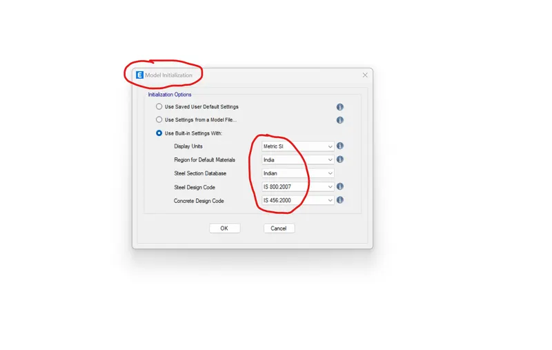
- The first step is setting the units and codes for the models to be created which are done in the model initialization box after opening a new model.
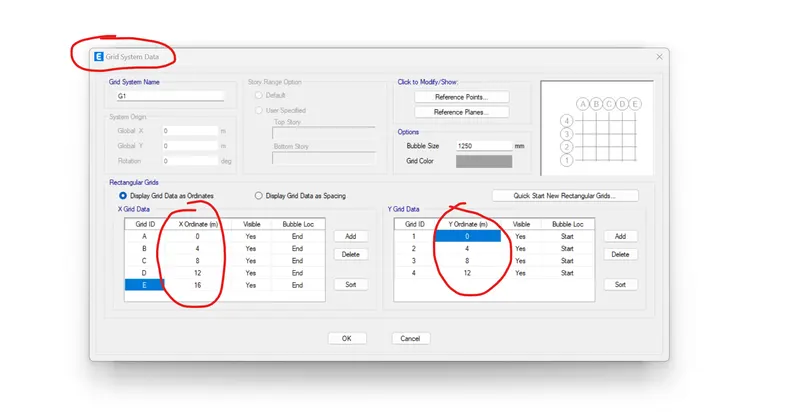
- The next step of grid creation is done using the custom grid data option and the distance between grids are fixed as 4m and 5 X grids and 4 Y grids as per the given criteria.
Model A:
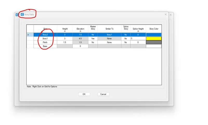
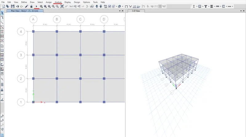
- After assigning the grid data, the storey data for the model is assigned. As it is a two storey model two storeys are added and first storey is fixed as master storey and other storey is given as similar storey and height is also defined.
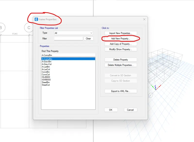
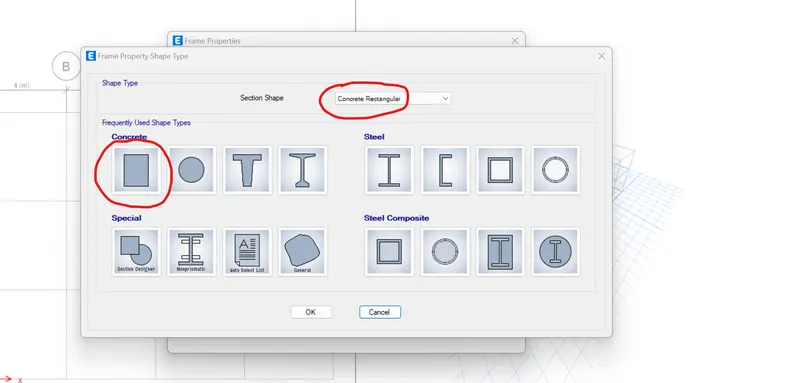
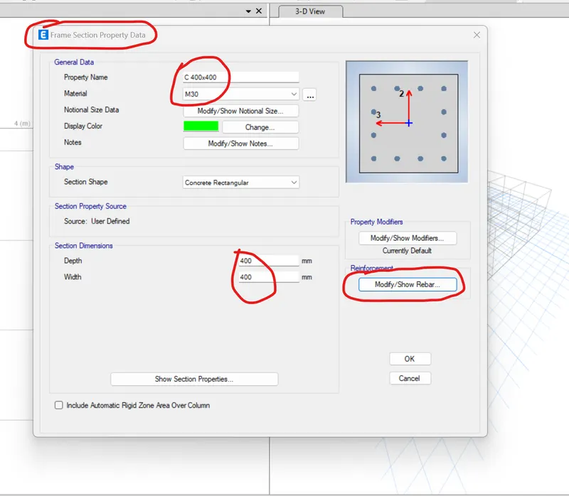
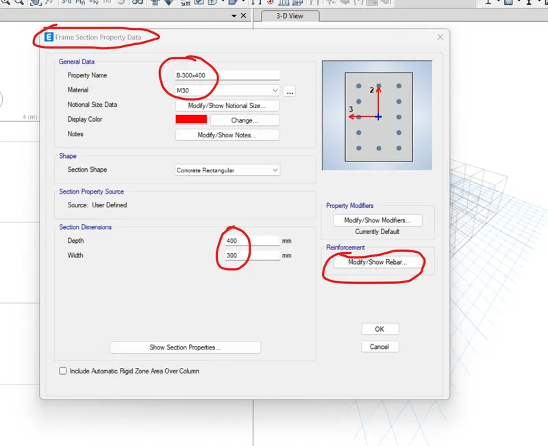
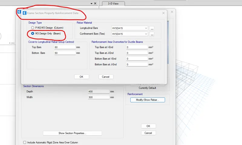
- Furthermore using the Define>Section properties>Frame sections>Add new property>Concrete rectangular commands the properties of beam and column are defined under the given conditions.
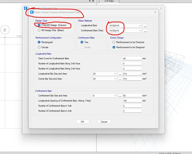
- In the Modify/Show rebar option design beam only option is given for beams and design columns option for columns and the rebar material and size can be chosen and properties are assigned.
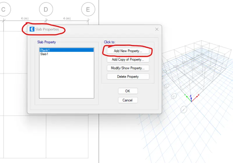
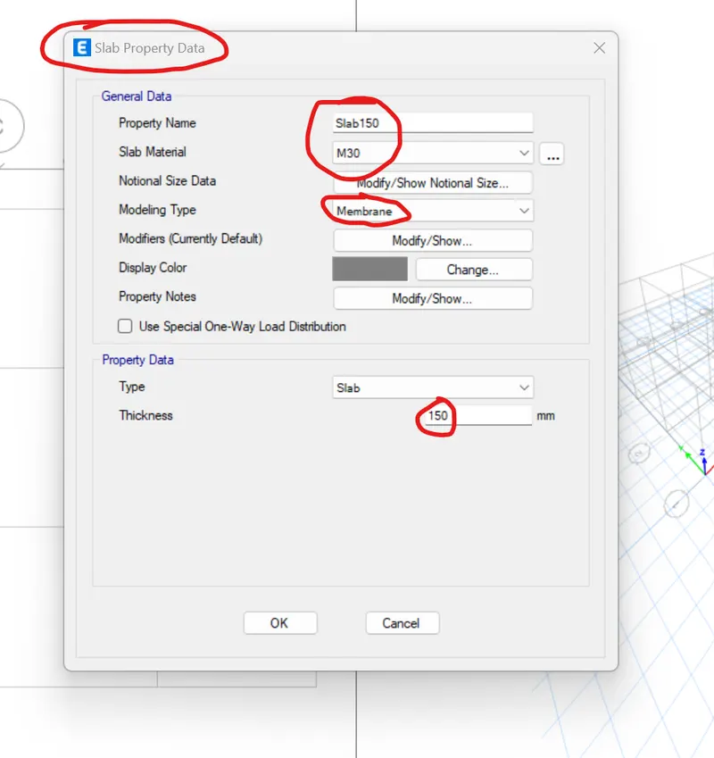
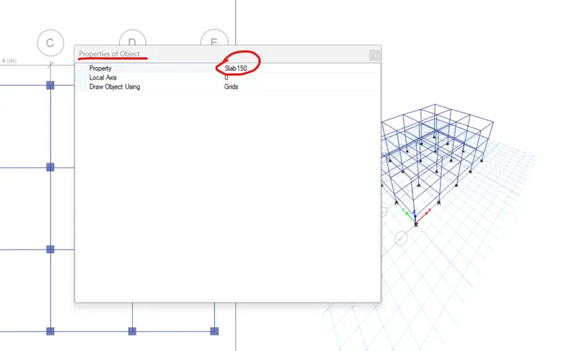
- Using slab sections option under the define command the properties of the slab are assigned.
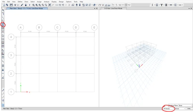
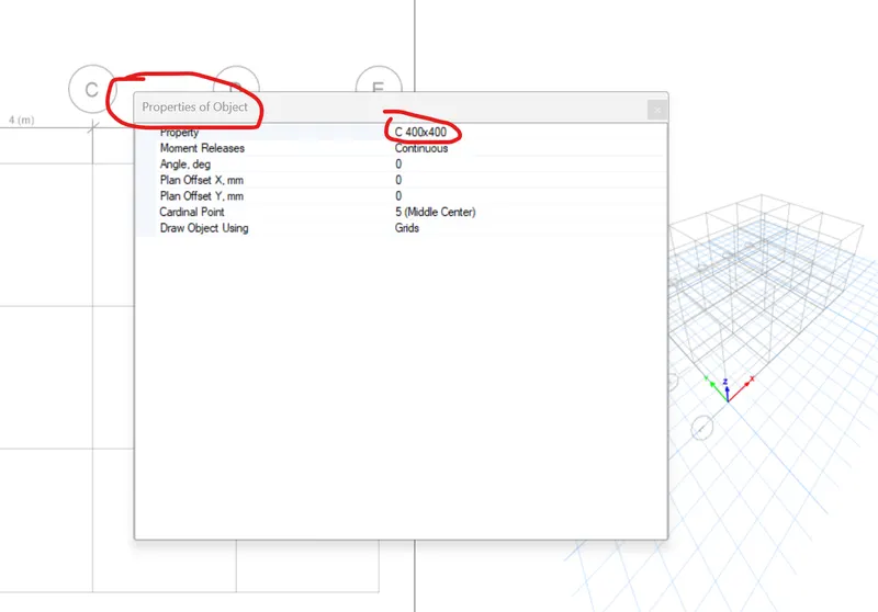
- Then using quick draw column tool in the left tool palette the columns are inserted in the model by selecting the intersection points of the grid. In addition to that all stories option is used as columns run from base to the roof of the structure.
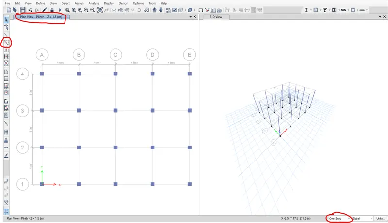
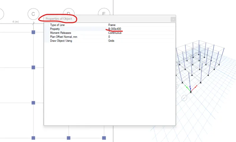
- For beam initially plint plan and one story option is selected, then using quick draw beam tool and selecting the grid lines between the columns, the beams are inserted.
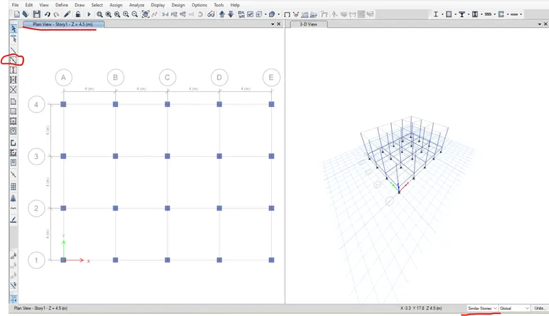
- Furthermore first floor plan and similar story is selected and using the same quick draw beam tool and selecting the grid lines between the columns, the beams are inserted.
- For slabs same frirst story plan and similar story option is selected and using the quick draw floor option and by selecting the grid spaces between beams and columns, the slabs are inserted thus, the complete struture model is done.
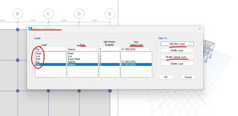
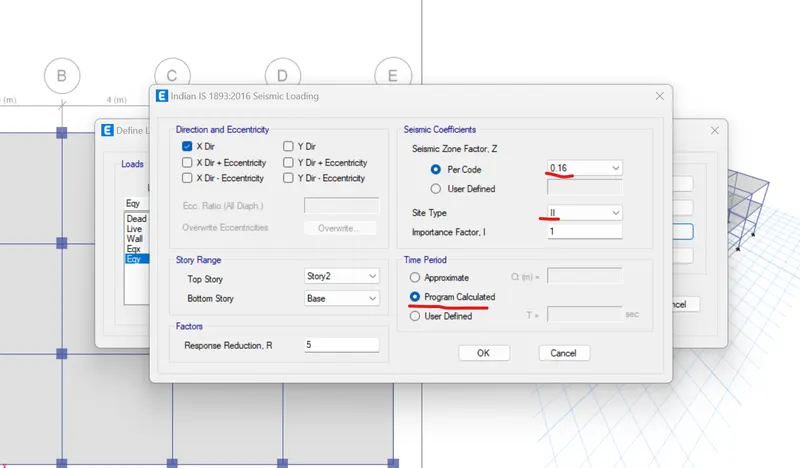
- After modelling, the next step is to define and assign loads to the structure. The loads of the structure are defined using the Define>Load patterns>Add new load command. For earthquake loads the corresponding code is selected and the conditions such as zone factor,soil type and direction are provided using the modify lateral load option and the loads are defined for the model.
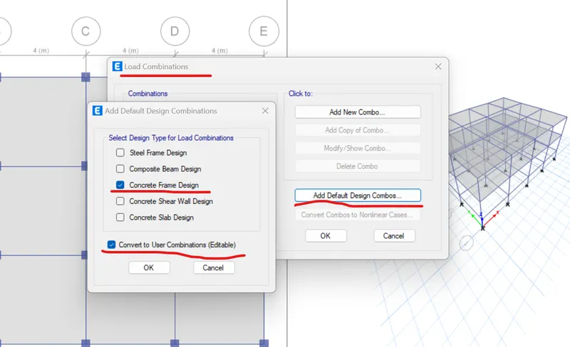
- Then using Define>Load combinations>Add default design combo>Concrete frame Design commads the load combinations are defined.
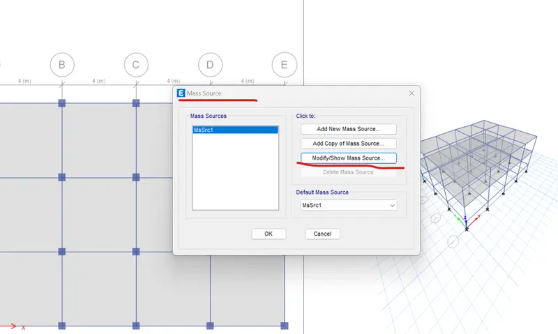
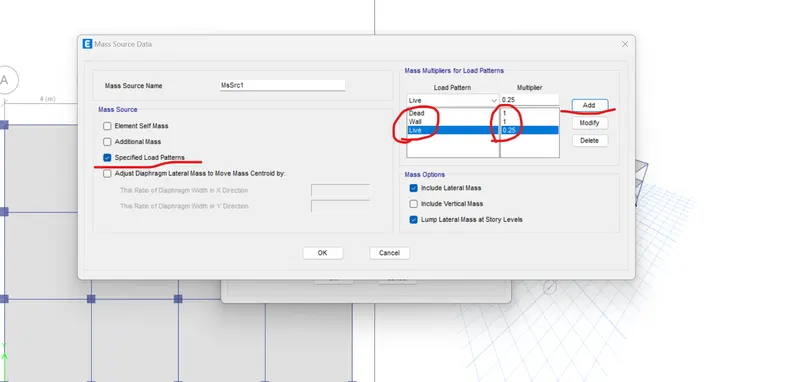
- Furthermore Mass source for Earthquake load is defined using the Mass source>Modify/Show mass source>Specified load patterns option under the define tab the mass source is defined. 25% of live load only is considered for the mass source which is defined in the above option.
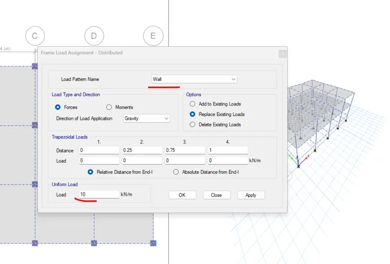
- For providing loads to the structure, first all the beams are selected and using Assign>Frame loads>Distributed command loads are assigned to the beams and the loads assigned are wall loads to the beams.
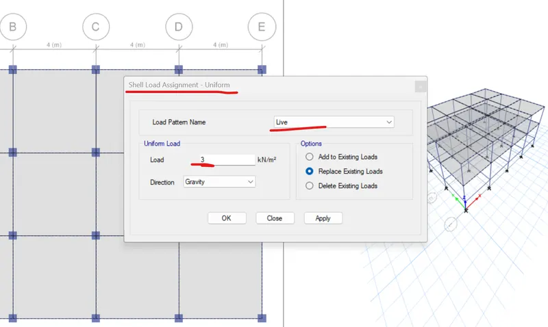
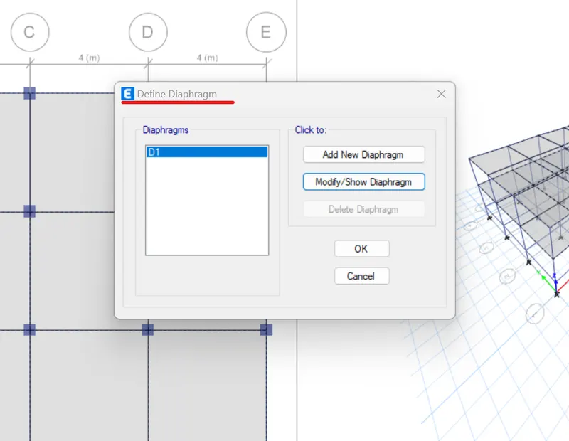
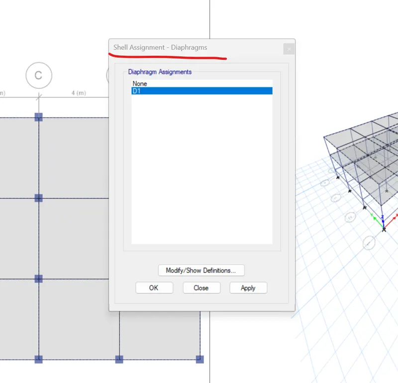
- For slabs, initially all the slabs are selected and using Assign>Shell loads>Distributed command loads are assigned and the loads assigned are live loads and using the diaphragm option in the shell command of the assign tab centre of mass is defined.
- Then using Run analysis option in the analyze tab analysis of the structure is done.
Model B:
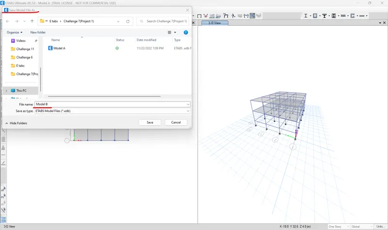
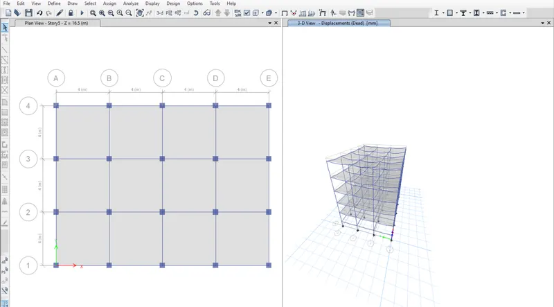
- Initially the model A is saved as model B using save as option.
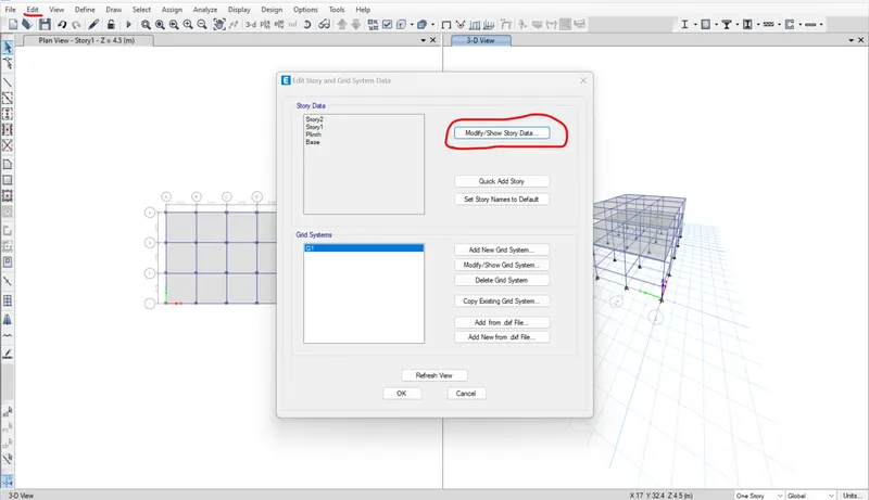
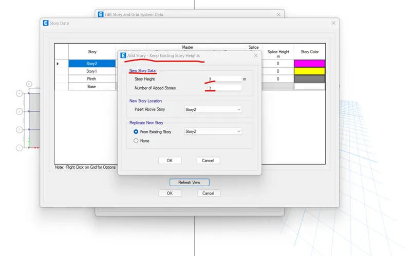
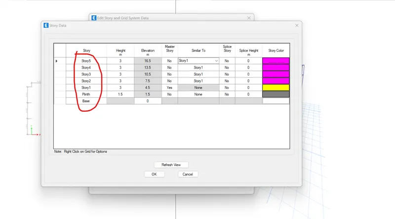
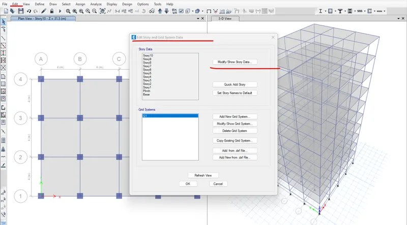
- Then using Edit>Edit Story and Grid data>Modify/Show story data option, 3 new storeys are added and the added storeys are selected with similar to 1st storey option and a 5 storey structure is created.
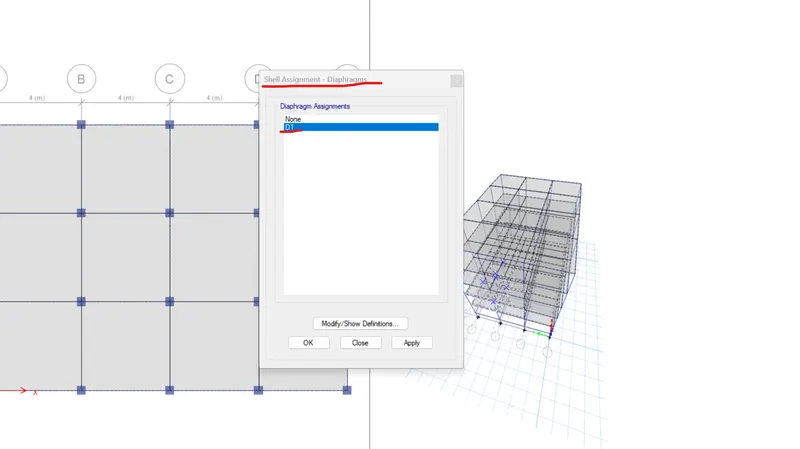
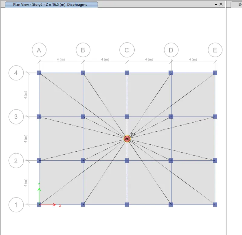
- Then all the slabs are selected and using Assign>Shell>diaphragm option the centre of mass is assigned
- Finally using run analysis option under the analyze tab analysis of the structure is done.
Model C:
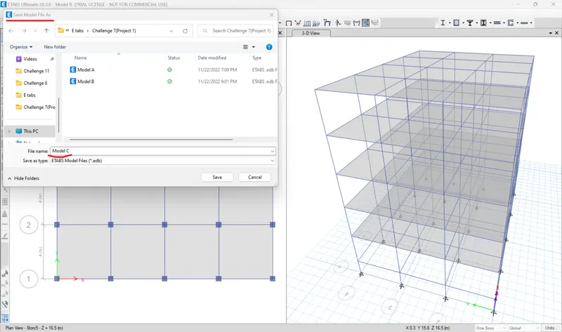
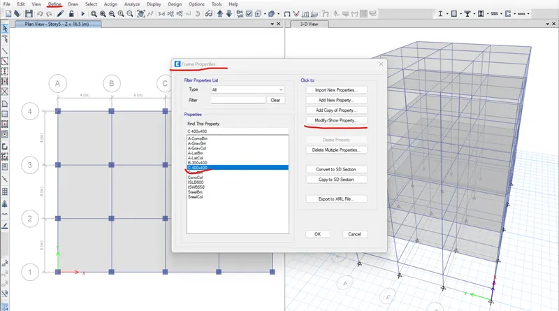
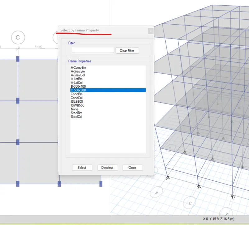
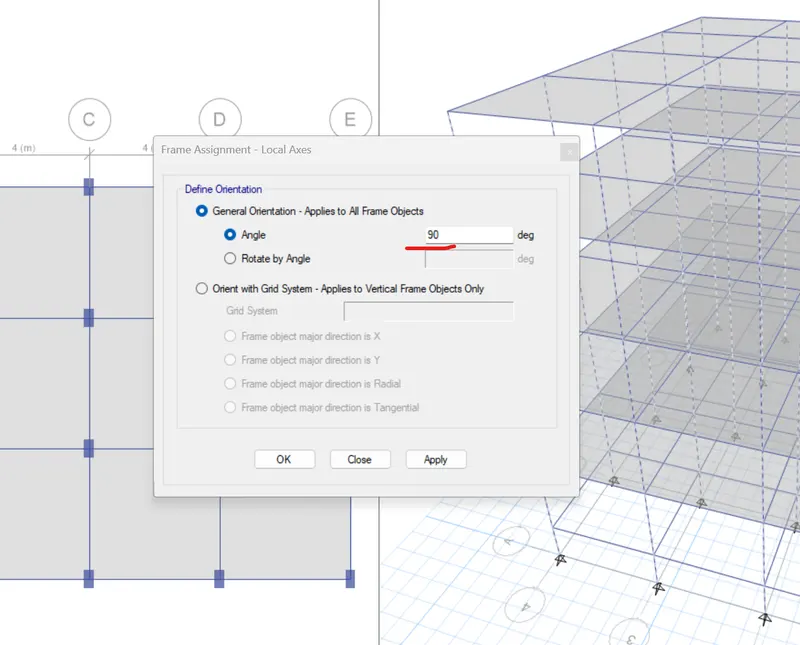
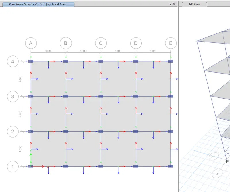
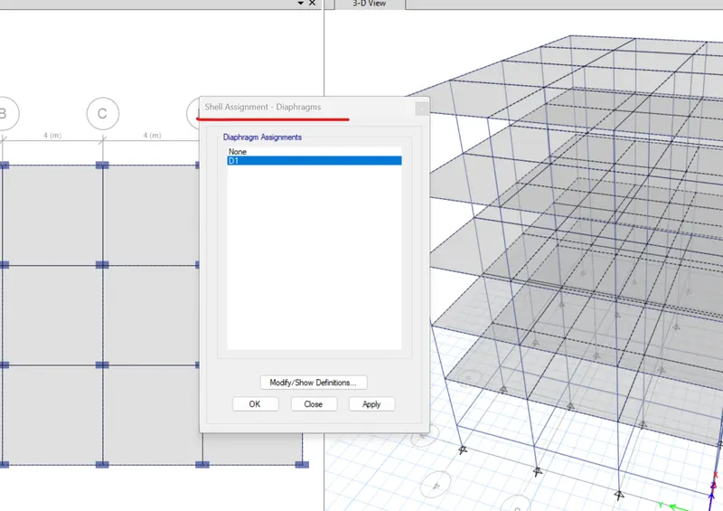
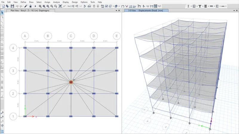
- Initially the model B is saved as model C using save as option.
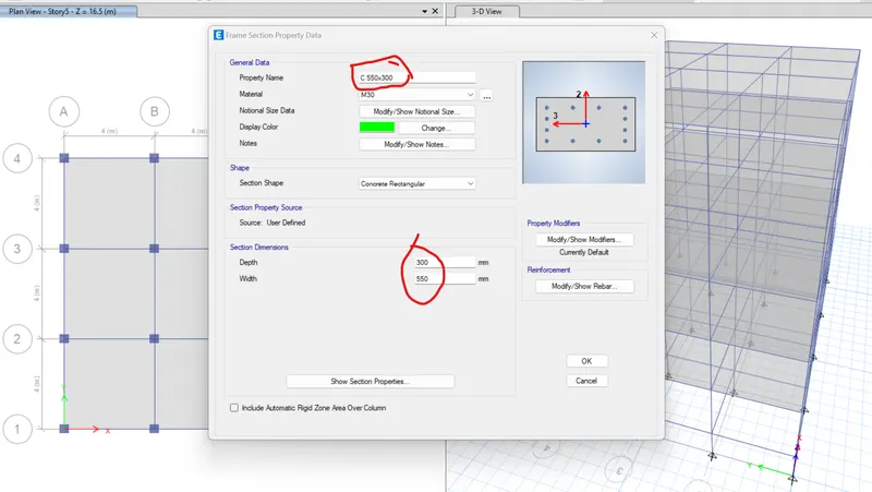
- In this model the column sizes varies from model B hence selcting the column from define>section properties>frame sections command and using the modify/show property the column sizes are changed.
- The larger size of the column is oriented along x direction using Assign>frame>local axes command by rotating the column 90deg
- Then all the slabs are selected and using Assign>Shell>diaphragm option the centre of mass is assigned
- Finally using run analysis option under the analyze tab analysis of the structure is done.
Model D:
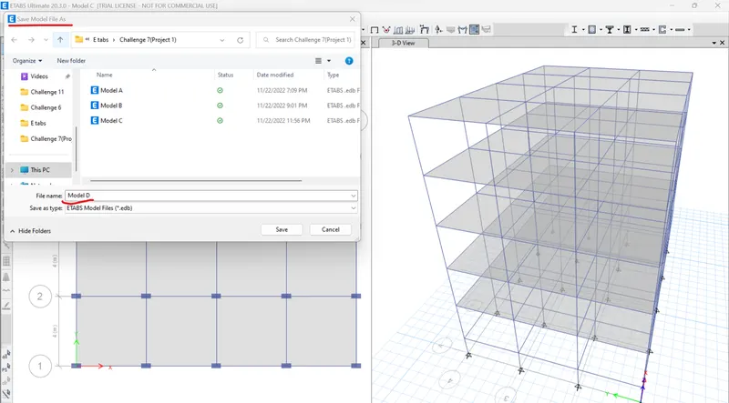

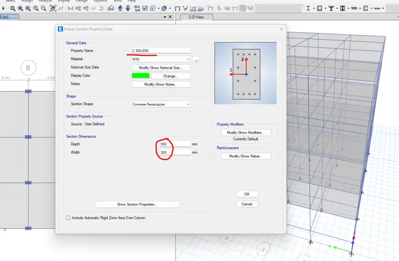
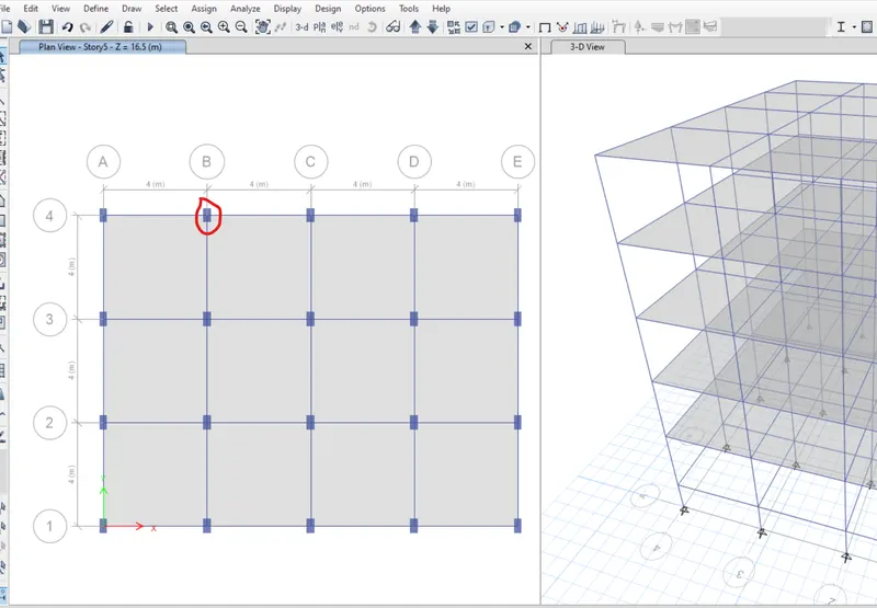
- Initially the model C is saved as model D using save as option.
- In this model the column orientation alone changes from x to y direction.
- The larger size of the column is oriented along y direction using Assign>frame>local axes command by rotating the column 90deg
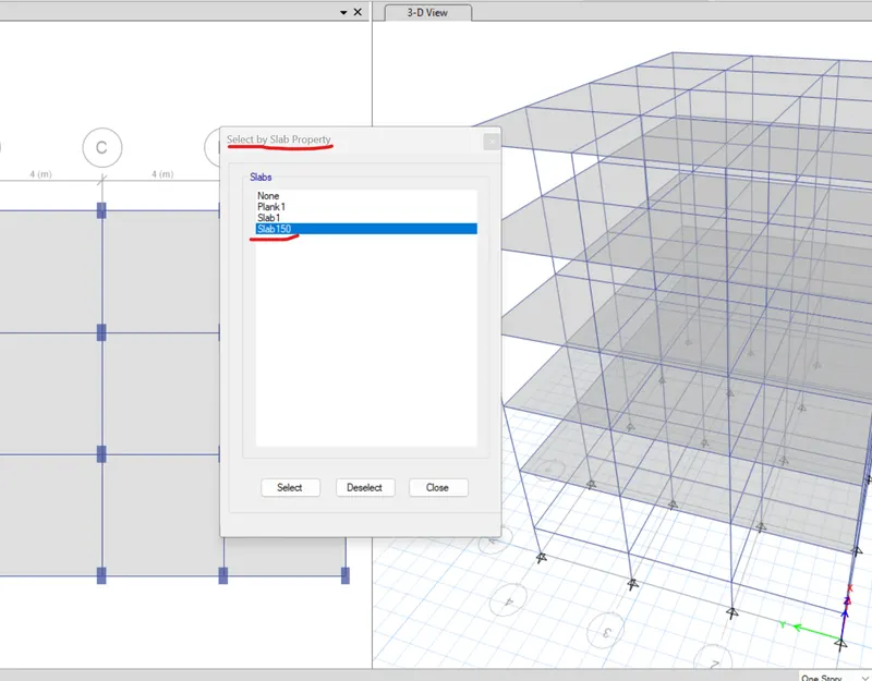
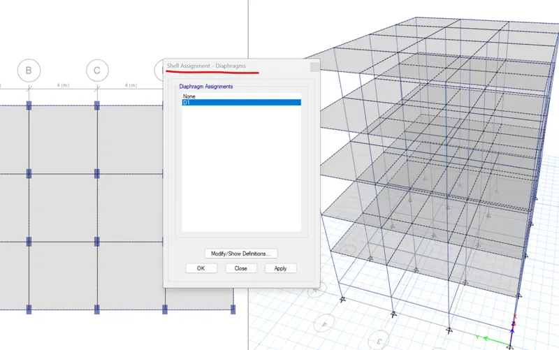
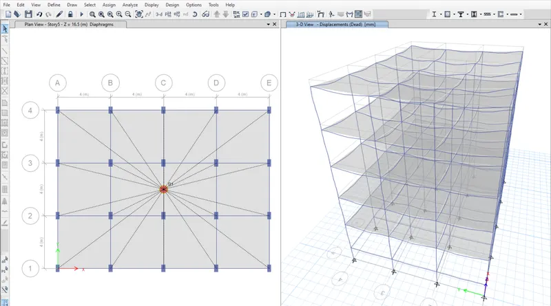
- Then all the slabs are selected and using Assign>Shell>diaphragm option the centre of mass is assigned
- Finally using run analysis option under the analyze tab analysis of the structure is done.
Model E:
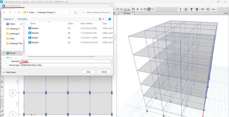
- Initially the model D is saved as model E using save as option.
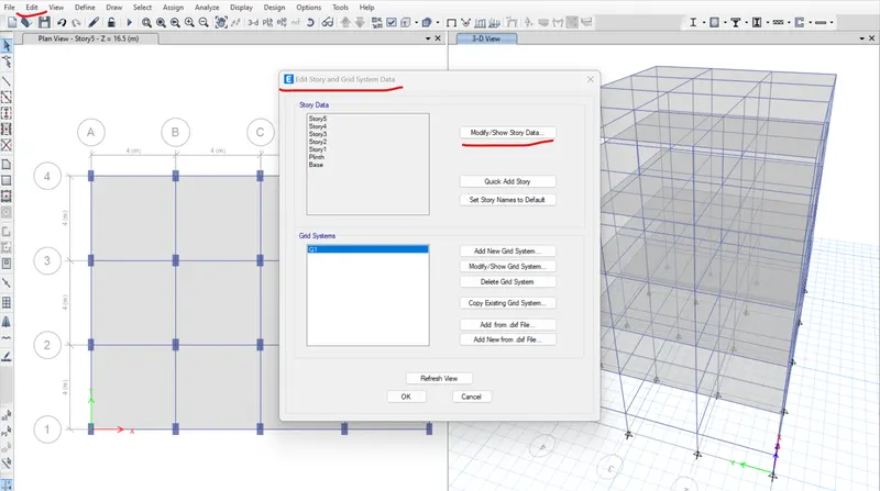
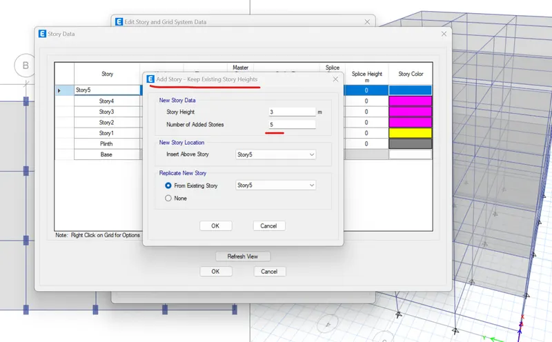
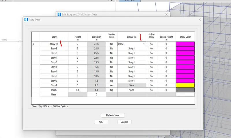
- Then using Edit>Edit Story and Grid data>Modify/Show story data option, 5 new storeys are added and the added storeys are selected with similar to 1st storey option and a 10 storey structure is created.
- In this model two column sizes are used for top 5 and bottom 4 storeys respectively
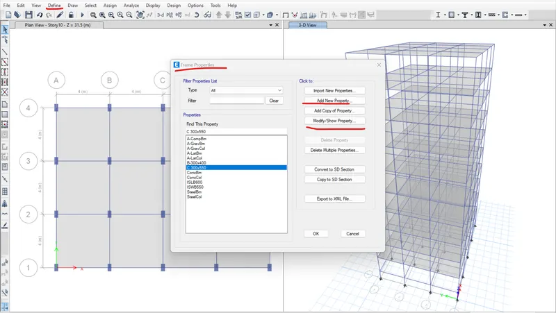
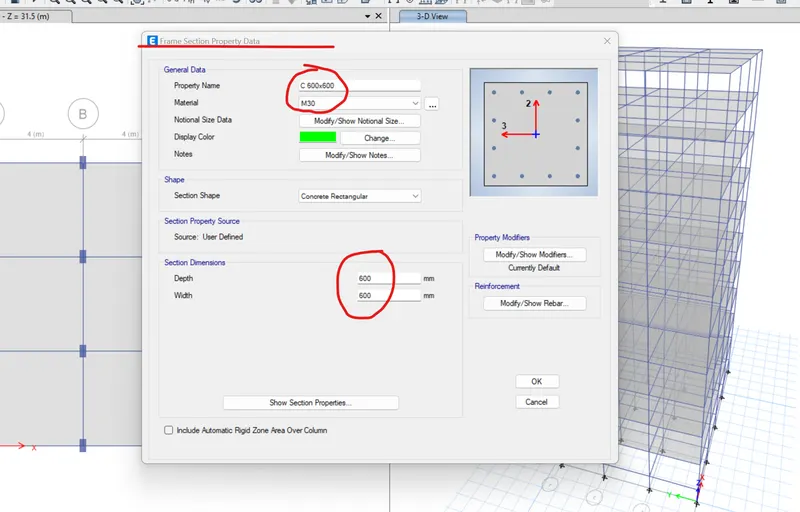
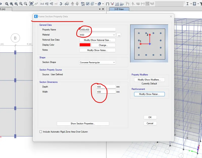
- Using Define>Section properties>frame>Modify/show property the column size is modified as 600x600 and using add new property option a new column of 400x400 dimension is created.
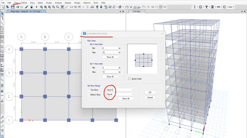
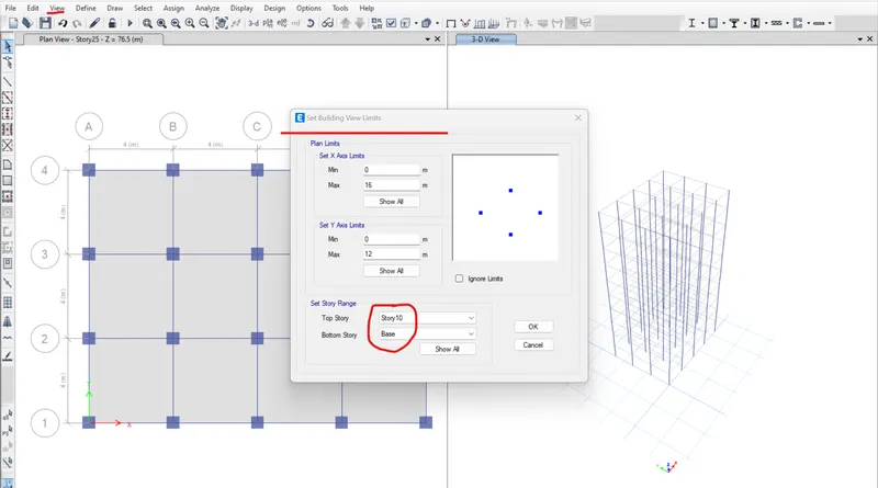
- As the previous model columns are modified into the size of 600x600 all the storey columns are in that size so inorder to change in top 5 storeys the 3d model window is opened and using View>set view building view limits the view range is set from story 10 to 6
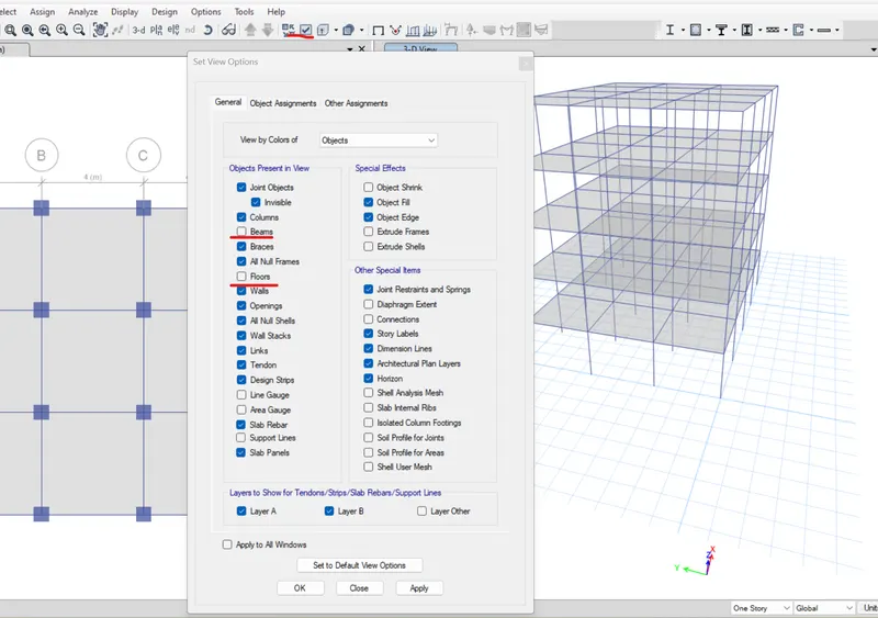
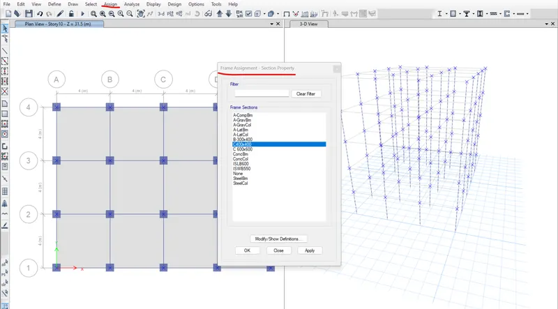
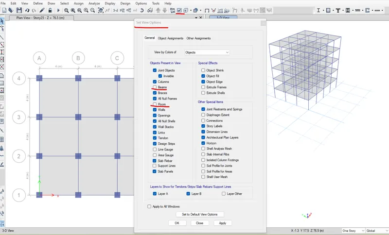
- Then using the View>Set view options beams and floors are hid from the view and all the columns are selected and using Assign>Frame>Section property, the top 5 story columns are assigned with 400x400 columns
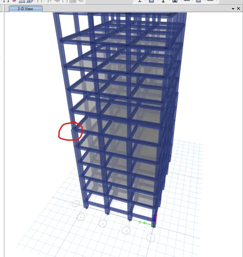
- Then all the views are restored to default and a 3d extruded view is also provided to differentiate the varying column sizes of the structure.
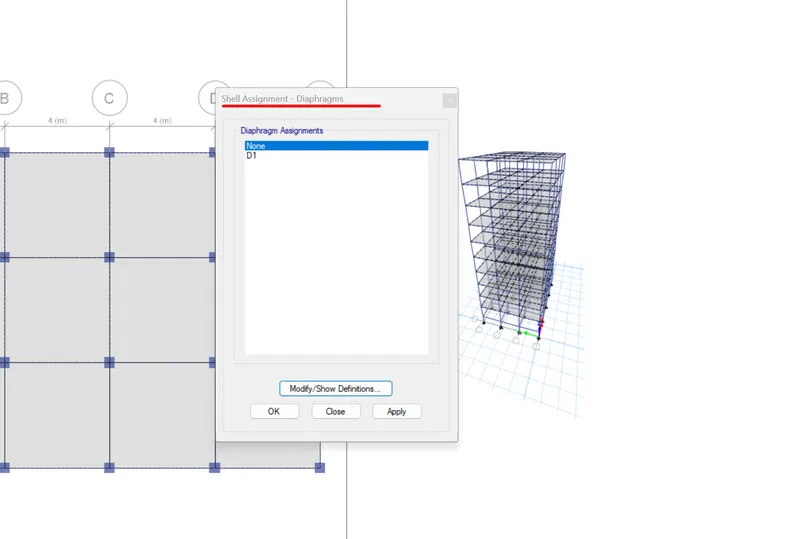
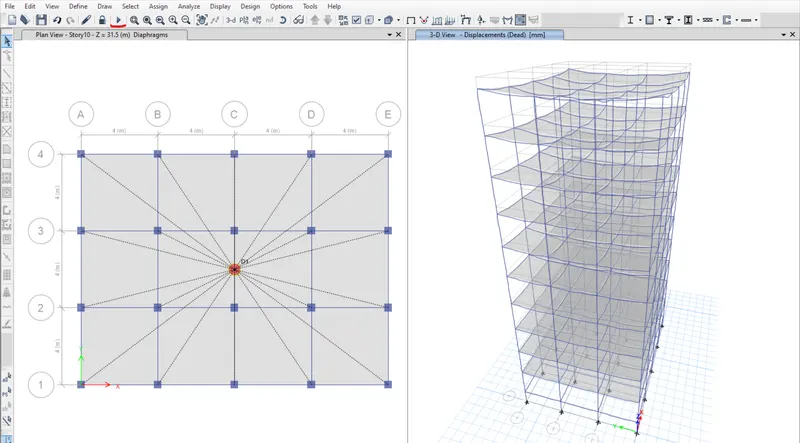
- Then all the slabs are selected and using Assign>Shell>diaphragm option the centre of mass is assigned
- Finally using run analysis option under the analyze tab analysis of the structure is done.
Model F:
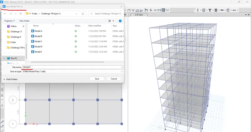
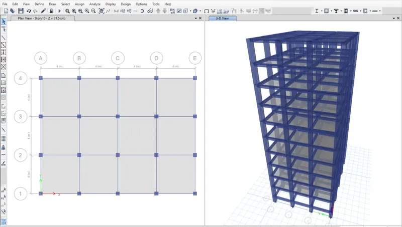
- Initially the model E is saved as model F using save as option.
- In this model all the columns have a uniform size of 600x600.
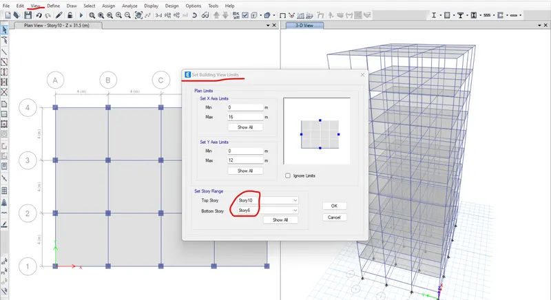
- So in the 3d model window using View>set view building view limits the view range is set from story 10 to 6
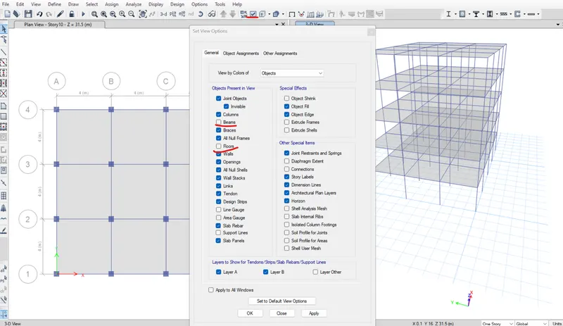
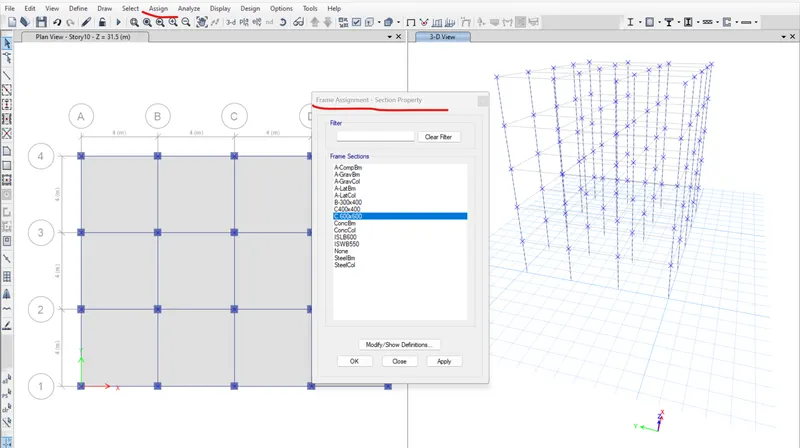
- Then using the View>Set view options beams and floors are hid from the view and all the columns are selected and using Assign>Frame>Section property, the bottom story columns are assigned with 600x600 columns
- Then all the views are restored to default and a 3d extruded view is also provided to view the uniform column sizes of the structure.
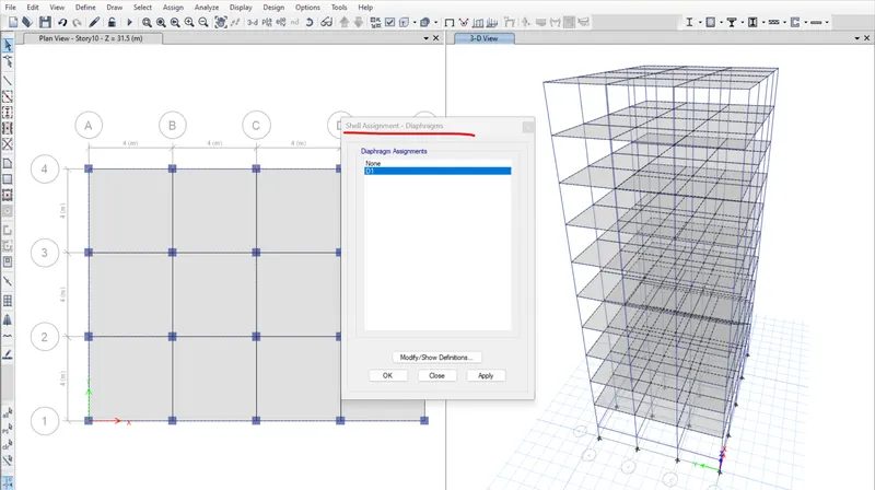
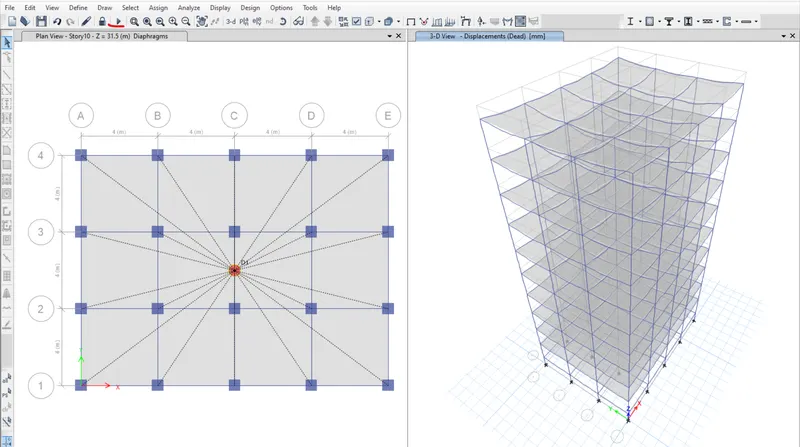
- Then all the slabs are selected and using Assign>Shell>diaphragm option the centre of mass is assigned
- Finally using run analysis option under the analyze tab analysis of the structure is done.
Model G:
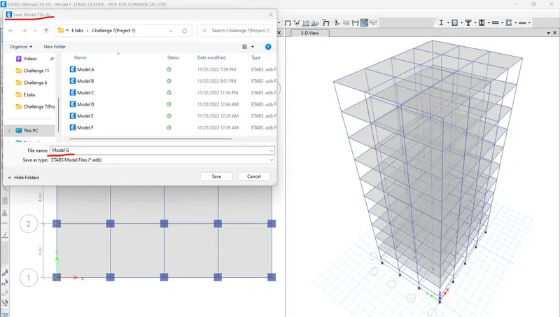
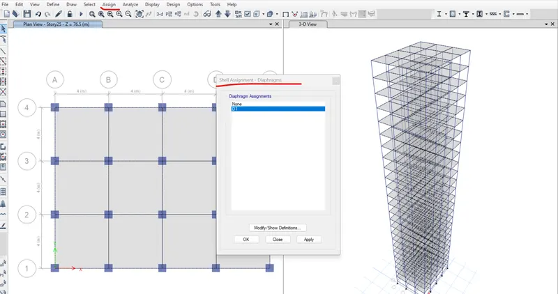
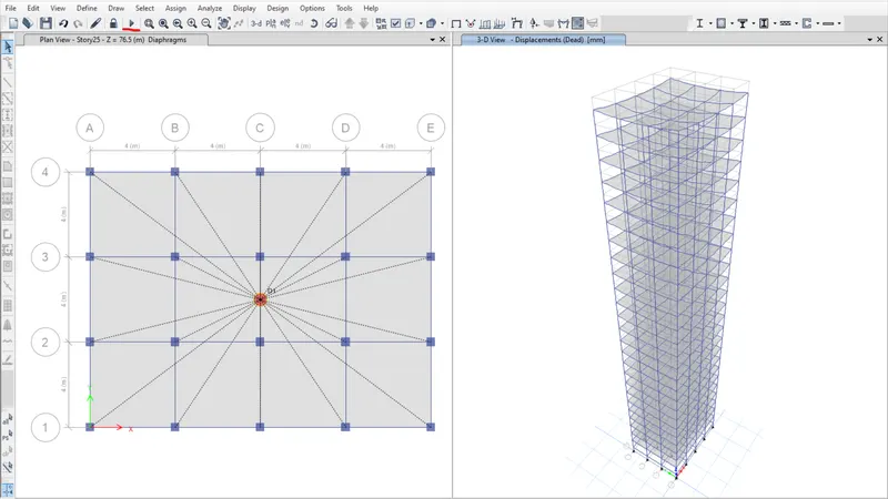
- Initially the model F is saved as model G using save as option.
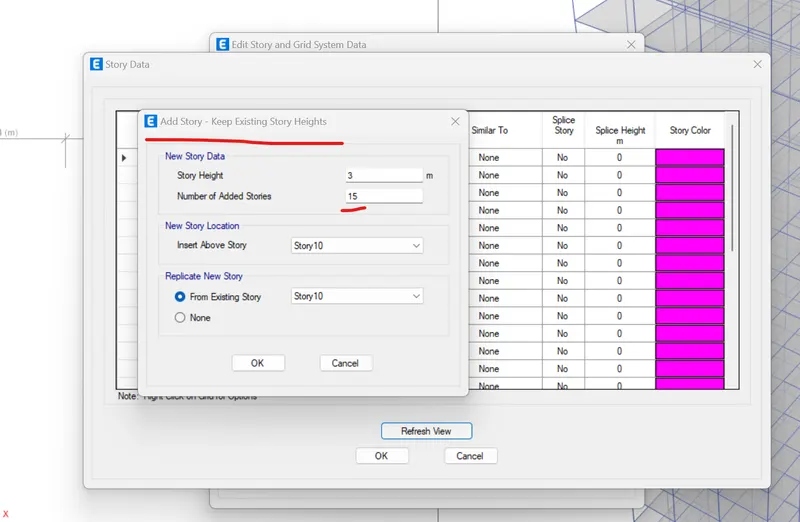
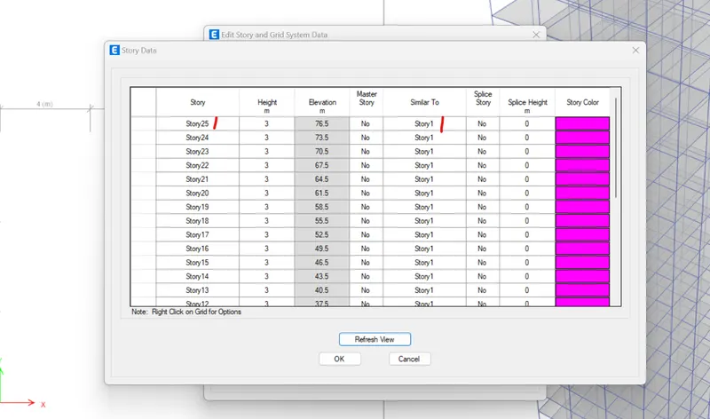
- The 1st step is to add storeys using Edit>Edit story and grid data>Modify/Show Story data>Add story commands more 15 storeys are added and similar to story 1 option is given.Hence a 25 storey structure is created.
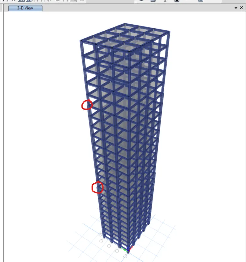
- In this model the columns are of different sizes with respect to storeys i.e, top 5 storeys,middle 10 storeys and bottom storeys has column sizes of 400x400,600x600 and 800x800 respectively.
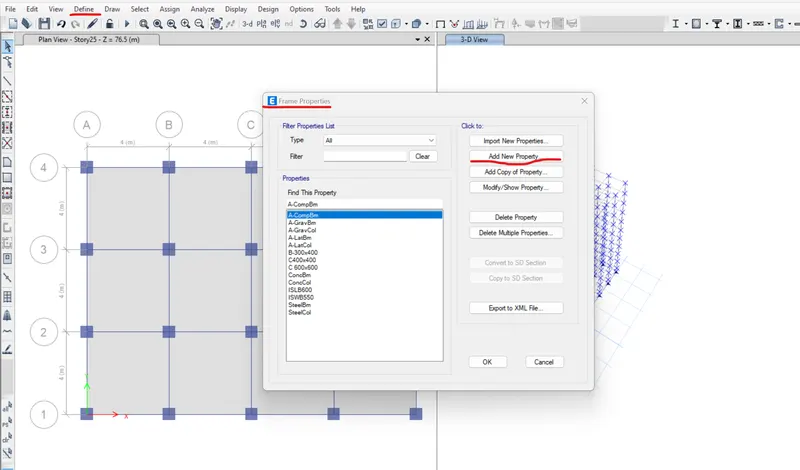
- In this model 400x400,600x600 are already defined hence using Define>Section property>Frame property>Add new property command 800x800 column is defined
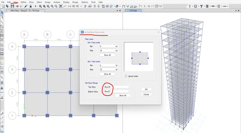
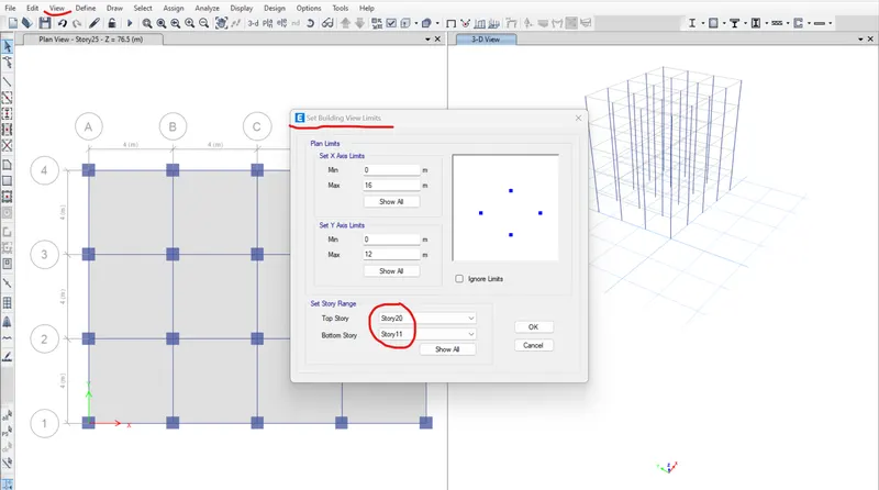
- So in the 3d model window using View>set view building view limits the view range is set from story 25 to 21
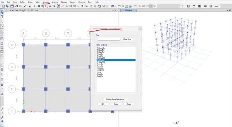
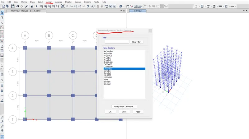
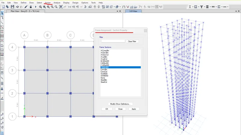
- Then using the View>Set view options beams and floors are hid from the view and all the columns are selected and using Assign>Frame>Section property, the top story columns are assigned with 400x400 columns.
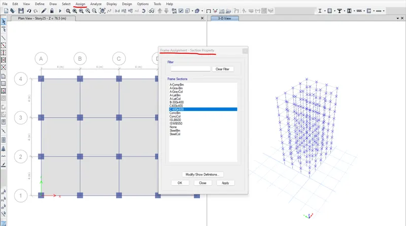
- Furthermore similarly the view range is set from story 20 to 11 and 10 to base and the columns sizes are assigned as 600x600 and 800x800 respectively.
- Then all the views are restored to default and a 3d extruded view is also provided to view the distinguished column sizes of the structure.
- Then all the slabs are selected and using Assign>Shell>diaphragm option the centre of mass is assigned
- Finally using run analysis option under the analyze tab analysis of the structure is done.
Model H:
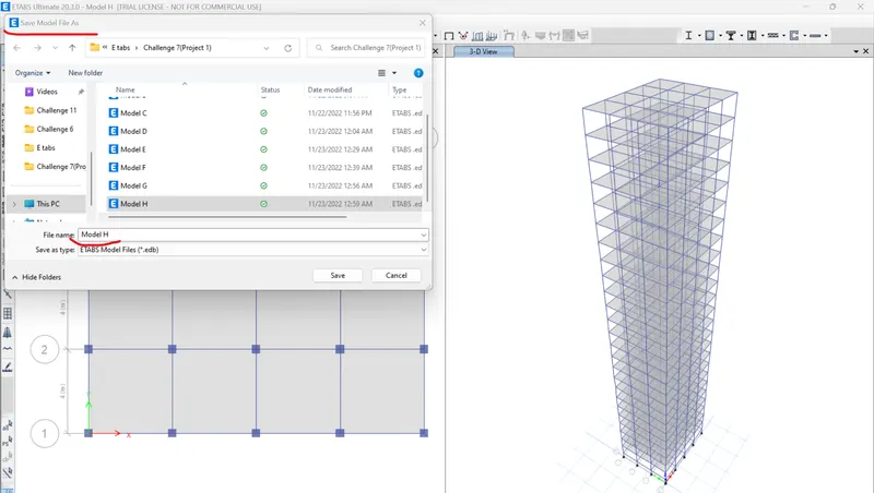
- Initially the model G is saved as model H using save as option.
- In this model the columns are uniform sizes of 800x800.
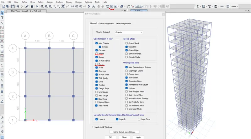
- Hence in the 3d model window using the View>Set view options beams and floors are hid from the view and all the columns are selected and using Assign>Frame>Section property, the top story columns are assigned with 800x800 columns.
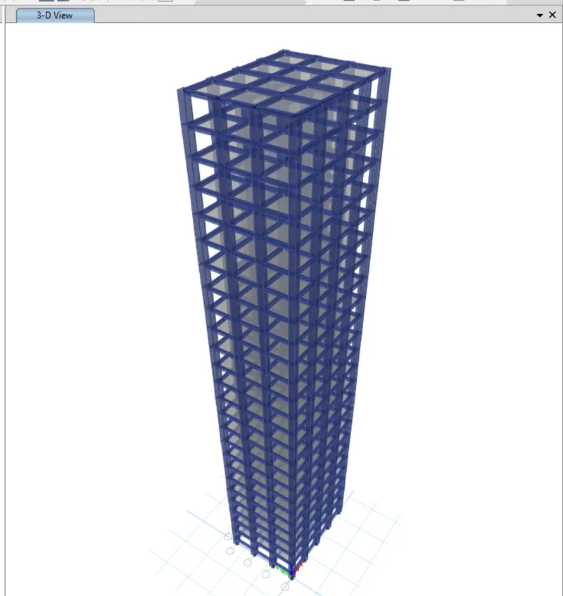
- Then all the views are restored to default and a 3d extruded view is also provided to view the uniform column sizes of the structure.
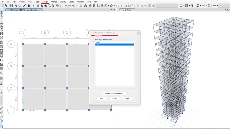
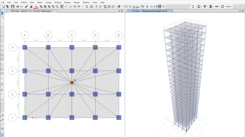
- Then all the slabs are selected and using Assign>Shell>diaphragm option the centre of mass is assigned
- Finally using run analysis option under the analyze tab analysis of the structure is done.
Model J:
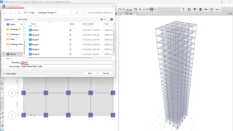
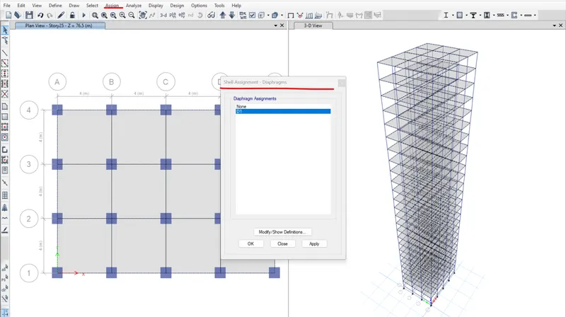
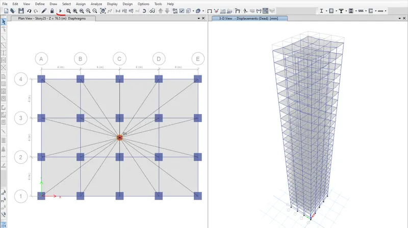
- Initially the model H is saved as model J using save as option.
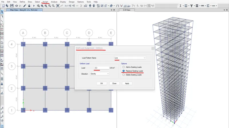
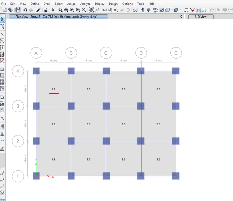
- This model is similar to Model H and the only difference is that it has 10% higher live load than H i.e, 3.3KN/m.
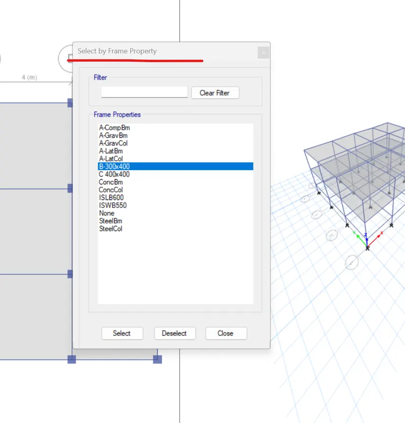
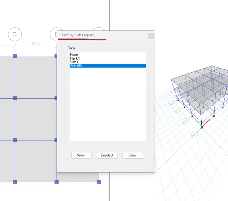
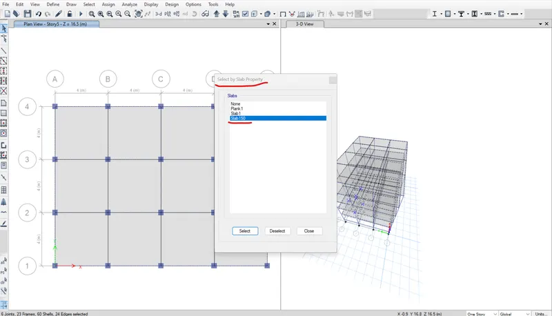
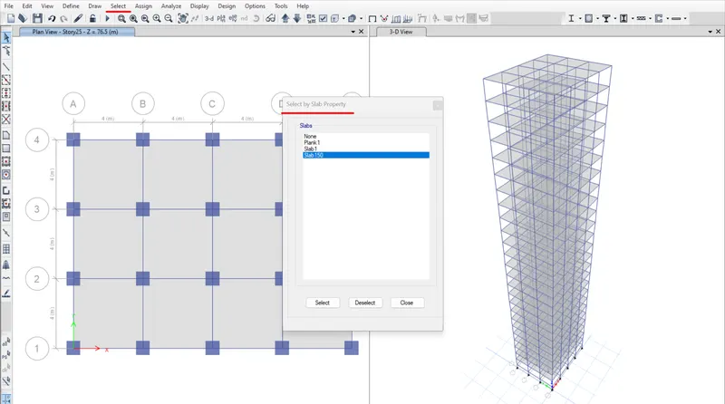
- All the slabs are selected using the select>property>Slab sections commands and using Assign>Shell loads>Uniform commands live load of 3.3KN/m is applied and replace existing loads option is selected before applying inorder to replace the existing live load.
- Then all the slabs are selected once again and using Assign>Shell>diaphragm option the centre of mass is assigned
- Finally using run analysis option under the analyze tab analysis of the structure is done.
Model K:
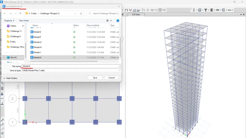
- Initially the model J is saved as model K using save as option.
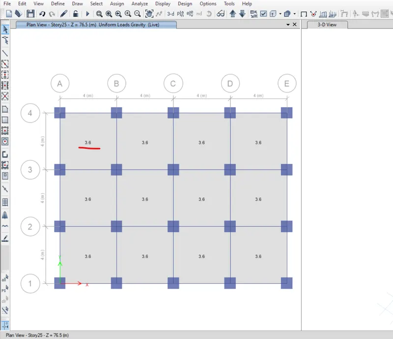
- This model is similar to Model J and the only difference is that it has live load than of 3.6KN/m.
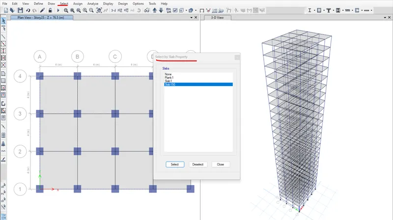
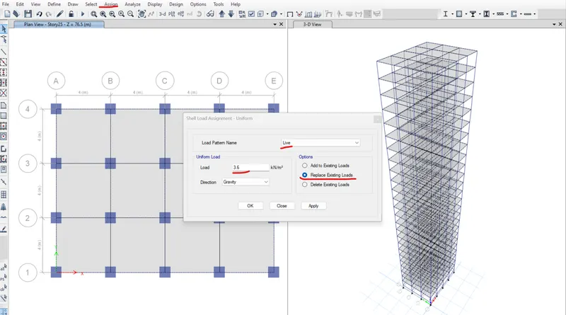
- All the slabs are selected using the select>property>Slab sections commands and using Assign>Shell loads>Uniform commands live load of 3.6KN/m is applied and replace existing loads option is selected before applying inorder to replace the existing live load.
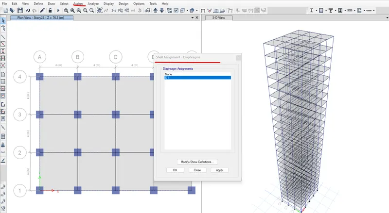
- Then all the slabs are selected once again and using Assign>Shell>diaphragm option the centre of mass is assigned
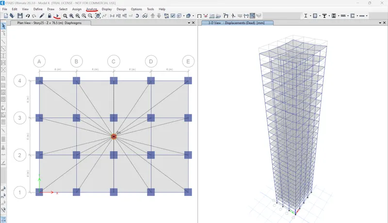
- Finally using run analysis option under the analyze tab analysis of the structure is done.
Results:
The analysed time periods of the structure are obtained using Display>Show table command and the effects and factors are compared and analyzed.
Effect of Stiffness on Time period: These effects are studied on E,F,G,H models and the obtained natural periods are
E-1.7s
F-1.7s
G-4.1s
H-4.4s
The E and F models are 10 storey structure and there is no difference identified in these models.
The G and H models are 25 storey building and model G has varying column sizes and H has a uniform column size throughout the structure. The model H has more time period because of the extra lumped mass at the top of the structure due to the greater column size at the top which further induces more lateral displacement and greater time period.
Effect of mass on Time period: The models studied for the mass effect are H,J,K and the obtained natural periods are
H-4.41s
J-4.42s
K-4.43s
There is no significant variation in time period as the mass is uniformly distributed in the structure.
Effect of building height on Time period: The models studied for this effect are A,B,F,H and the obtained natural periods are
A-0.5s
B-1.03s
F-1.7s
H-4.4s
It can be clearly seen that the time period increases with increase in building height as the height of the building is directly propotional to time period of the structure as per IS 1893.
Effect of Column Orientation: Models B,C,D are studied for this effect and the recorded values are
B-1.03s
C-1.14s
D-1.12s
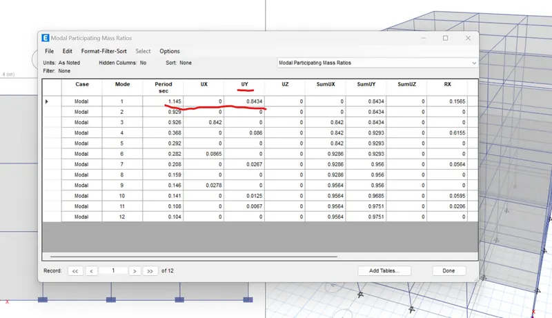
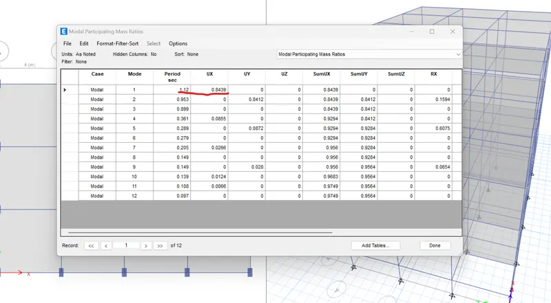
In both the models C and D it can be clearly seen from the above images is that the direction in which the column is oriented subjected less deflection and time period than the direction in which the smaller side of the column is oriented.
Effect of flexural stiffness: For this effect model B is modified as B1 by providing flexural strength of beam as 10% instead of 100%. The time period before and after modifying are
B-1.03s
B1-2.62s
The time period value is appeared to be almost doubled in B1 as flexural strngth of the beam plays a major role in resisting the structure from collapse during earthquake.
Effect of axial stiffness:For this effect model H is modified as H1 by providing axial cross section as 10% instead of 100%.The time period before and after modifying are
H-4.4s
H1-5.99s
The time period obviously increases as axial cross section is one of the mandatory conditions for any structure to prevent from failure or collapse.The deformations observed are massive after the analysis of H1 because of no axial stiffness provied in columns.
Effect of fixity: For this effect the modified model B1 is used where the time period having pinned support is already noted and the change of support is done as fixed and upon running analysis another time period is noted.The time periods arrived after the analysis are
Pinned - 1.03s
Fixed - 0.94s
The time period decreased as fixed support does not allow any torsional moments also along with two translational moments at the base.
Hence number of models has been created,analysed and the results are interpreted based on the effects of dynamic characteristics of the building.