Project 1 : CFD Meshing for Tesla Cyber Truck
Objective :
- To Identifying & cleanup all the topological errors in the given Tesla Cyber Truck Car model.
- To create a surface mesh.
- To Create a wind tunnel around Tesla Cyber Truck Car .
- To create a volumetric mesh to perform an external flow CFD analysis simulation
Procedure:
Steps for Importing and Preparing the CAD Model:
- Import the CAD model.
- Identify and clean up any topological or geometric errors.
- Perform a geometry check.
- Set up relevant PIDs (Property IDs).
- Define the element size or length.
- Configure mesh parameters, select the meshing type, and generate the surface mesh of the CAD model.
- Resolve any errors in the surface mesh.
- Create the wind tunnel for external flow CFD analysis and generate the surface mesh of the wind tunnel.
- Generate the volumetric mesh.
Import CAD model:
To import the CAD model, follow these steps:
- Go to the File menu.
- Select Open.
- Browse to the location of the CAD model.
- Select the CAD model file.
- Click Open.
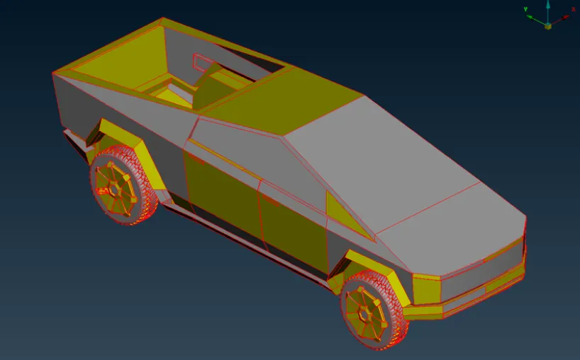
- In the image above, we can see only single cons. To better understand the model and identify the actual single cons, let's apply topo to the entire model. The image below shows the model after performing the topo operation.
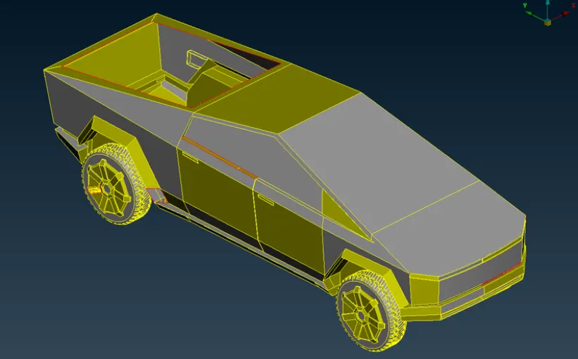
- The imported model initially opens in ENT mode. To view it in PID mode, select PID mode from the bottom layout.
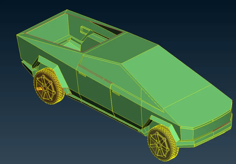
- Now, let's switch to wireframe mode to more clearly identify any topological errors in our model.
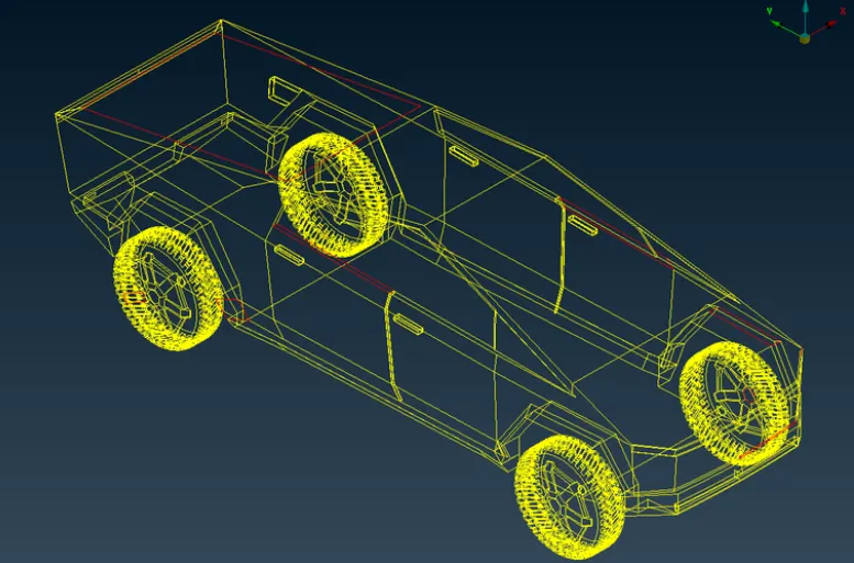
- In the wireframe mode of our model, we can clearly see errors such as single cons. Let's address and correct these topo errors one by one.
Identify and clean up any topological or geometric errors:
- Before starting the topo cleanup, you'll notice that the resolution of the components isn't very high. To improve this, let's first go to the mesh deck, select the entire model, and reduce the mesh length to 1mm. As shown in the image below, this results in a significantly improved resolution of the car.
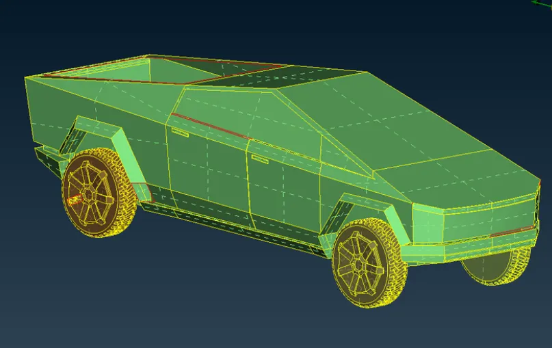
- As we've observed, the geometry contains several topological errors, including missing faces indicated by single and triple cons. For CFD analysis, only double cons are acceptable, as triple cons can create unwanted local volumes.
- The goal is to ensure the entire interior of the car forms a single volume. In this model, the tires are inserted into the body but are not attached. We have two approaches to address this issue:
- Delete the overlapping parts, perform topo, and merge the car and tires into a single volume.
- Delete the overlapping parts and close the holes, so that the car forms one volume, and each tire forms a separate volume. This results in five volumes in total—four for the tires and one for the car. Additionally, another volume will form between the car and the wind tunnel, which is the volume needed for the external flow analysis. We will delete all other volumes and retain the final volume, as this is required for the external flow analysis.
- We will follow the second approach, as it is more suitable. Initially, the model had many errors, and each should be systematically rectified, focusing on individual features such as the lights, wheels, windshield, and body. Our primary concern is with the exterior features of the car, not the interior.
- To ensure the entire model forms a single volume, we must have only double cons, without any features closed on all sides, as this could create separate local volumes. When encountering small surfaces, it's best to delete them along with their neighboring surfaces and create a larger surface to avoid any quality issues during meshing.
- We will delete unnecessary surfaces that cause errors or could lead to the creation of local volumes. If you are unsure about a selection, zoom in and carefully choose the correct surface. Also, use wireframe mode for more accurate selection (using Ctrl + Shift or by turning off shadow mode).
- We will switch between PID and entity modes as needed, depending on the problem at hand. In all cases, depending on the situation, we will use tools such as project, extend, cut, topo, and new cons to resolve topo errors.
- Following these guidelines, we will address topo errors one by one, starting with the body and then moving on to the wheels.
Body Part:
- To address the body part, we'll start by patching the open surfaces. Depending on the situation, we can use tools like coons, fitted, or fill hole to create new surfaces. If you delete a surface and need to create a new one in its place, you'll need cons (curves).
- To retain the footprint of a deleted surface in an empty space, use the con2curve tool before deletion. By selecting this option and the cons, a reference curve is created in that area.
- There are various approaches to resolve errors, and the key is to choose the one that best suits your needs. Regardless of the method used, the ultimate goal is to delete all unnecessary cons and surfaces to ensure that no extra local volumes are created.
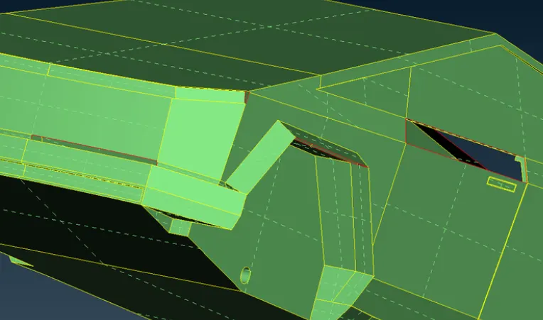
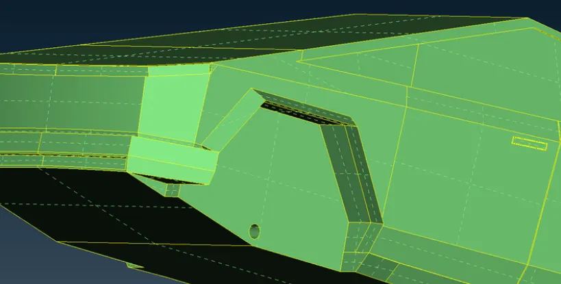
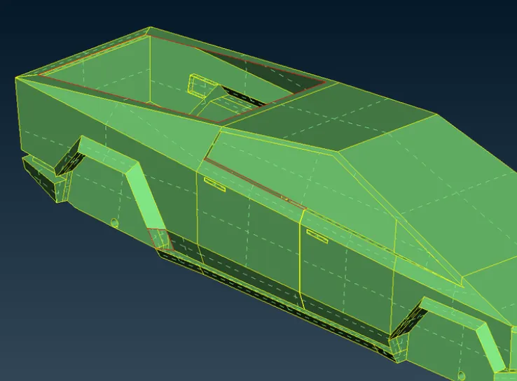
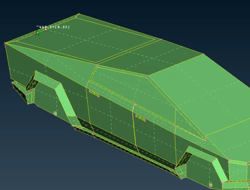
Body component inside before topo clean up:
The tires are inserted into the body but are not attached. As previously mentioned, we will delete the overlapping areas between the tires and the body, then close the holes to ensure that the car forms a single volume. Since the tires are not attached, each tire will form a separate volume. In the image below, we can clearly see the extended sections where the wheels are inserted.
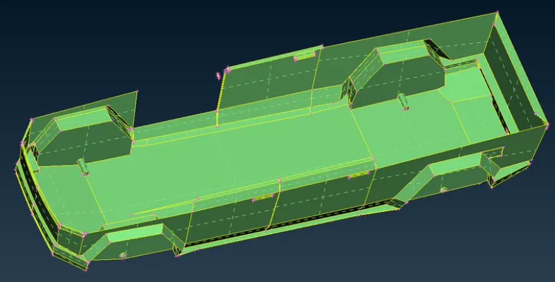
- In the above section, making the wheels visible reveals glitches, indicating overlapping surfaces. We will delete these overlapping areas and close the volume. The image below clearly shows the glitched extended sections where the wheels are inserted.
- We have removed the extra parts from both the wheels and the body, as they were inside and creating unwanted volumes. By deleting these, we prevent the formation of any local volumes. The image below shows the deleted glitched extended sections where the wheels were inserted. Next, we need to close the remaining holes to ensure there are no open surfaces.
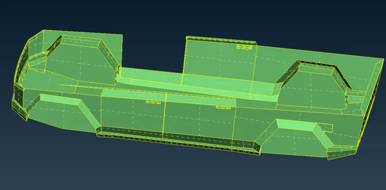
- To patch the holes and achieve a clear geometry, we deleted the old surfaces around the holes and created new surfaces for the body near all four wheels.
- The image below shows the body component from the inside after topo cleanup. The surface appears clear and neat following the cleanup process.
Rims and Tires:
- The image below shows the rims and tires before topo cleanup.
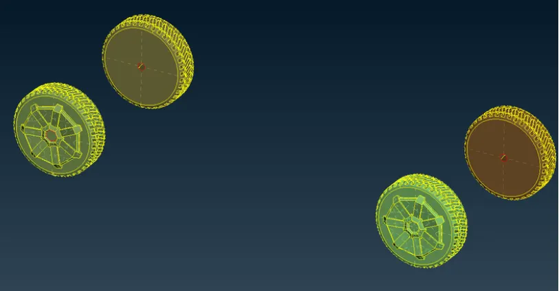
- Since we removed the wheel attachments to create separate volumes, we now have open surfaces for the wheels. To patch these holes and achieve a clear geometry, we deleted the old surfaces around the holes and created new ones for all four wheels. Additionally, we patched the open surfaces in other areas using coons and fill hole.
- If no triple cons are visible in your model, it indicates that the model is hollow inside, meaning it lacks any internal attached surfaces and has only one common external volume.
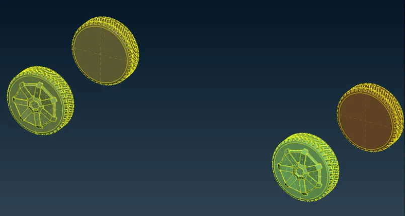
- The image below shows the rims and tires after topo cleanup.
Perform Geometry Check:
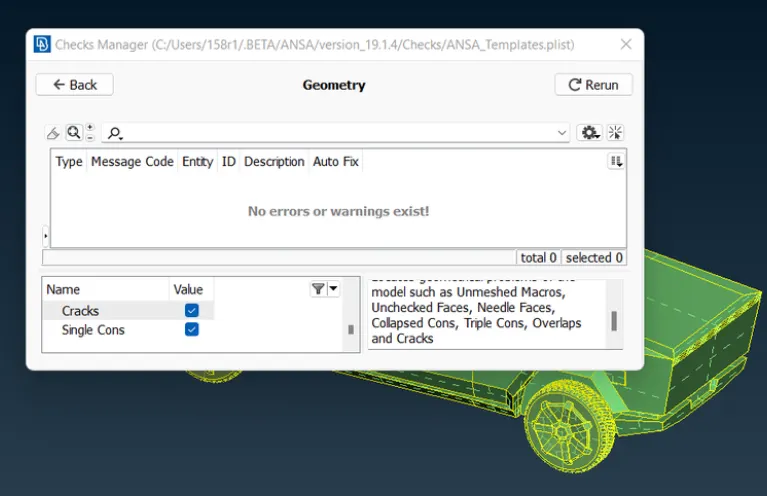
After resolving all the topological errors, the geometry is verified using geometry checks under the checks manager.
The image below shows the checks manager after performing these geometry checks, confirming that no errors are present.
Set up relevant PIDs (Property IDs).
- In this step, we assign PIDs (Property IDs) to different parts of the model, naming and coloring them to differentiate between components and simplify working on them individually. This also helps in specifying boundary conditions for various parts. Before setting up PIDs, ensure that cross hatches are activated.
- When you open the properties manager at the top, you will see some default PIDs already assigned. We need to create new PIDs for our components. To create a new PID, right-click in the properties manager, select "New," choose "pshell," and then confirm by selecting "pshell" again. In the popup box, enter a name for the PID and click "OK." To change the color, double-click on the color box, select the desired color, and click "OK."
- Repeat this process to create PIDs for all components. You can also add transparency to the windows for a more realistic appearance by adjusting the color settings.
- Next, assign these PIDs to the corresponding geometry components. To apply a PID, select it in the PID manager, right-click, choose "Apply," and then select the cross hatch of the surface you want to assign the PID to within the geometry. Confirm by middle-clicking. Use the various selection tools to accurately select the required surfaces.
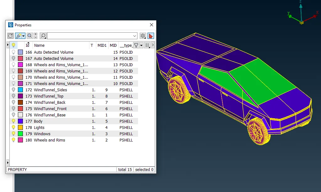
- Once the PIDs are assigned, delete any empty original PIDs that no longer have components assigned by using the compress function. The image below displays the list of PIDs that have been assigned.
Defining the element size or length and setting the mesh parameters & creating the surface mesh and resolving the errors in the surface mesh:
Mesh lengths are applied as follows:
- Windows: 2mm
- Body: 5mm
- Lights: 4mm
- Tires and Rims: 2mm
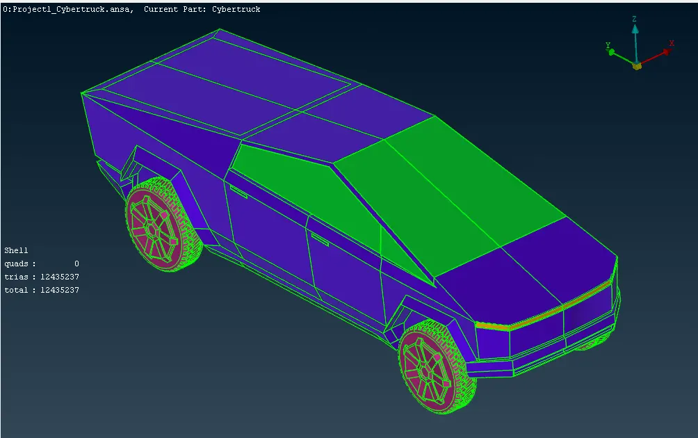
For these mesh lengths, the appropriate maximum and minimum values are applied. The truck body is meshed last, with perimeter length applied only to the cons that are not connected to other PIDs, ensuring that no meshed surfaces are deleted.
Switching to hidden mode allows us to identify off meshes. The reconstruct tool is used to significantly reduce off meshes, and any remaining issues are corrected using the smooth and split tools.
Creating the wind tunnel for external flow CFD analysis:
To perform an external flow CFD analysis, a wind tunnel needs to be created around the car. This is done in TOPO mode by creating a rectangular box around the vehicle.
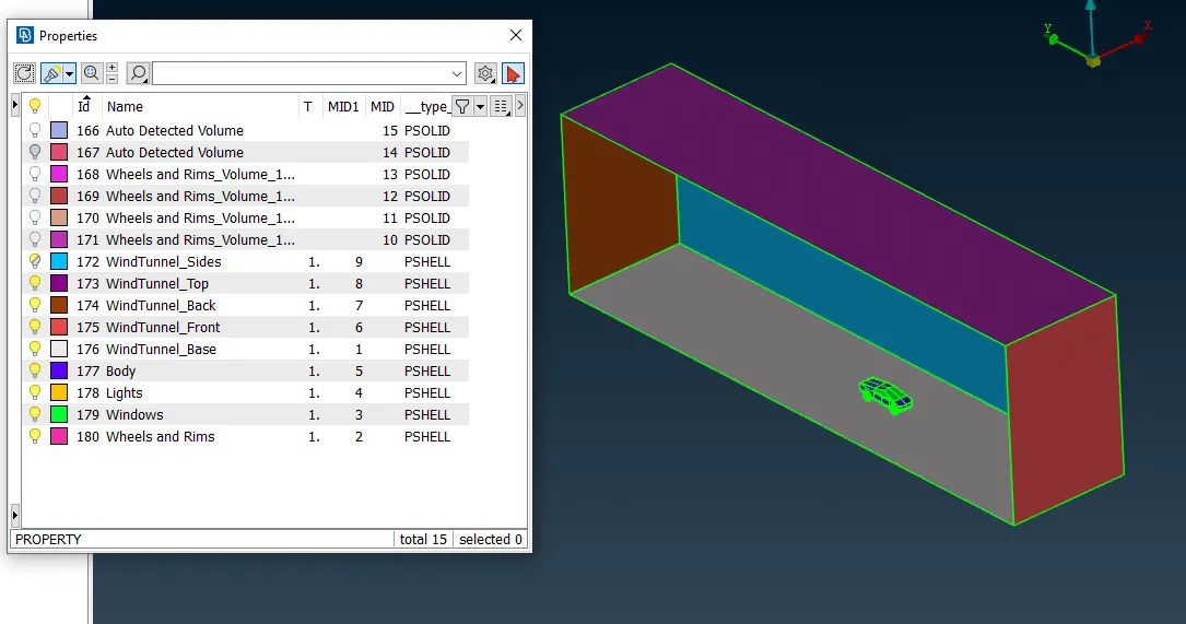
Surface meshed wind tunnel:
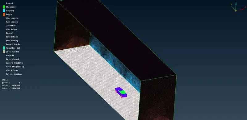
Note: The wind tunnel volume is not meshed due to the significant time and/or high computing power required.
Conclusion:
- The imported CAD model of the Tesla Cybertruck has been topologically cleaned and all feasible surface errors have been corrected to prepare for external aerodynamic analysis.
- The surface mesh has been generated with the specified element size, and the mesh has been reconstructed to meet the required quality, particularly at corners and edge intersections.
- Any mesh errors encountered were addressed, and a wind tunnel was created for the external aerodynamic analysis.
Through this project, we have gained experience in several key areas:
- Identifying and cleaning up topological and geometry errors.
- Performing geometry checks, setting up relevant PIDs, and defining element sizes or lengths.
- Setting mesh parameters and quality criteria, selecting the appropriate meshing type, and generating the surface mesh of the CAD model.
- Using the Quality Criteria tool and exploring various options under shell parameters such as skewness, minimum length, maximum length, maximum angle, and minimum angle.
- Resolving errors like skewness and min/max lengths using various tools.
- Setting up a wind tunnel according to specified dimensions for external flow CFD analysis and generating the surface mesh of the wind tunnel.
Link to the model:
https://drive.google.com/file/d/1WDx03hFdwBI7on3ogRHRyvjnG6DLuBqZ/view?usp=sharing