Project 1 : CFD Meshing for Tesla Cyber Truck
AIM:
For the given model, to check and solve all geometrical errors on half portion and Assign appropriate PIDs and to perform meshing with the given Target length and element Quality criteria. After meshing the half model to do symmetry to the other side.
DESCRIPTION:
PROCEDURE FOLLOWED:
- The Tesla cyber truck model is loaded in to ANSA software.
- Then a Topo clean up is done first using topo tool and the single / triple cons are found.
- The errors are elemenated accordingly with the model.
- Then the geometry checks is performed for the mode.
- Then for each compoenent with varying target lengths the meshing is performed.
- Then the wind tunnel is created accordingly.
- Wind tunnel is then meshed.
- Then the vloumetric mesh is performed keeping the required volumes i.e volume between the truck and the tunnel for CFD and other volumes are deleted.
- Thus, the experiment is completed.
TOPO/GEOMETRY CLEANUP:
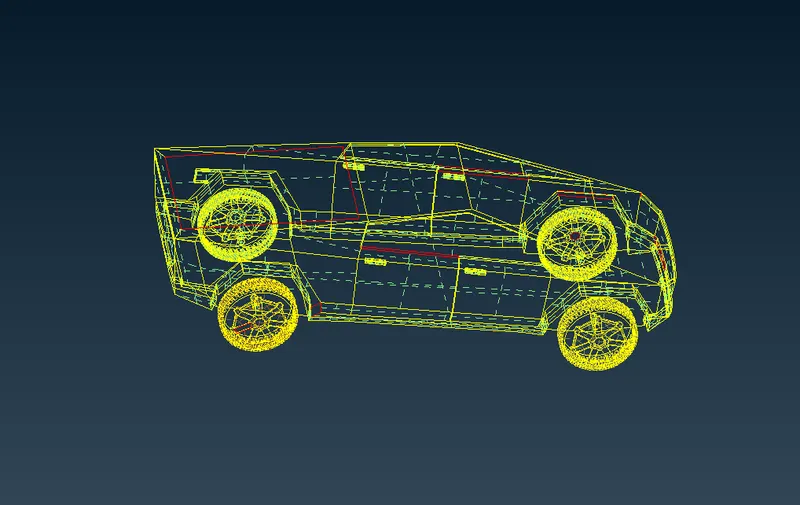
Loading the model in the ANSA we see as follows
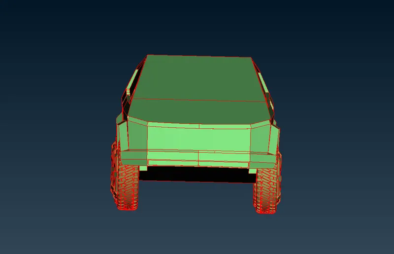
Doing topo to the model
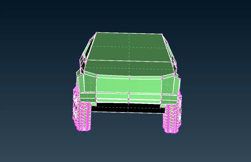
we see change into double, single and triple cons
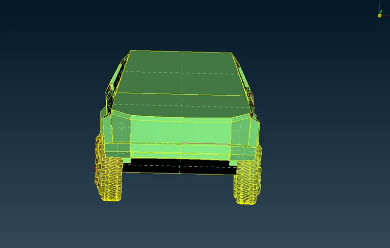
Now doing the con resolution to the model with Meshing then Length>perimeters with 1mm and macros with 1mm
we see a good geometry model now as follows
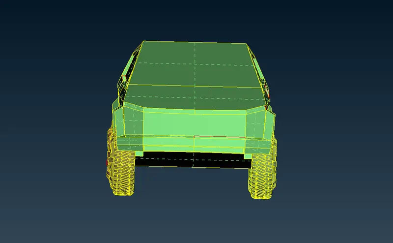
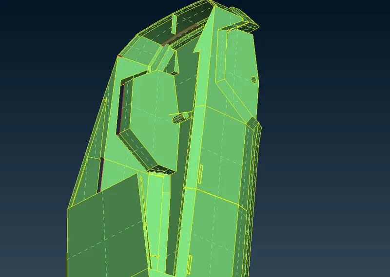
Now fixing the single cons present in the model
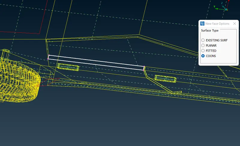
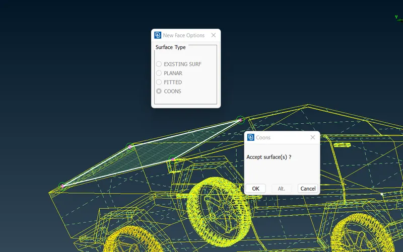
Filling the gaps using coons
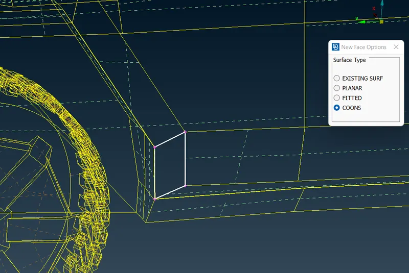
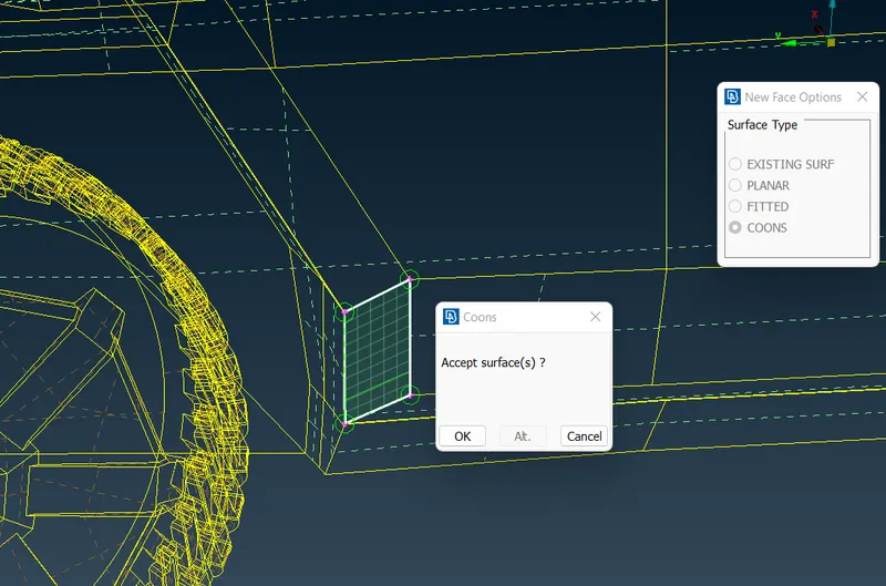
creating surfaces with other single cons
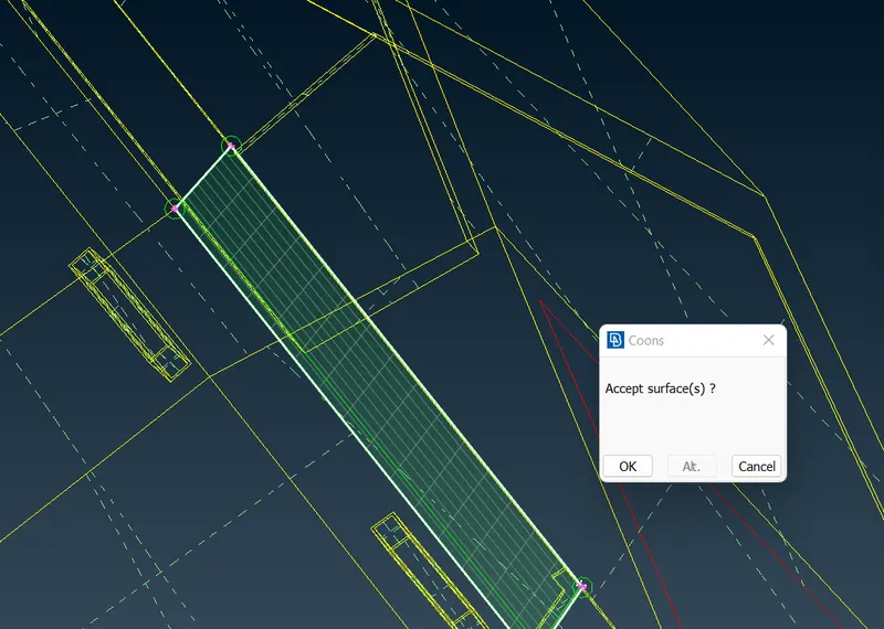
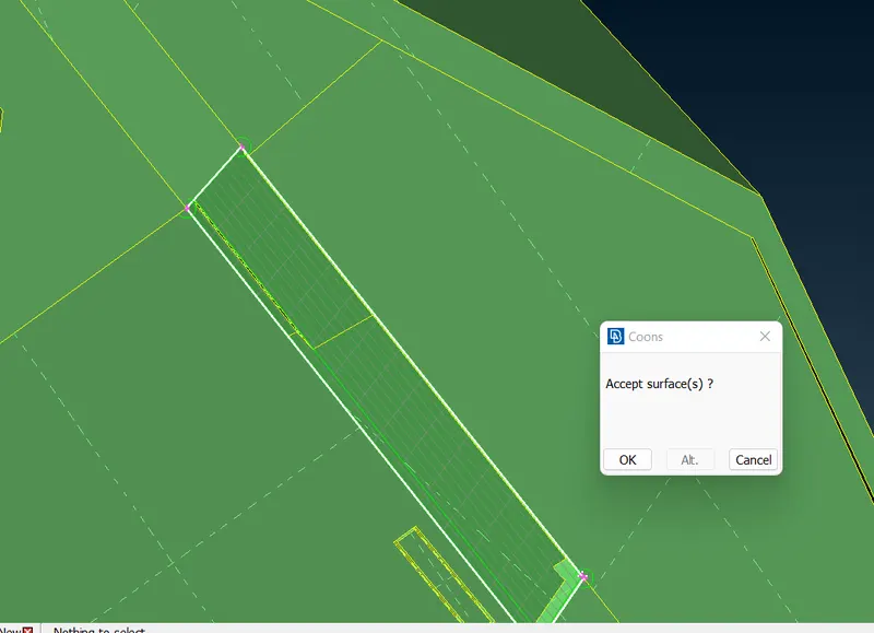
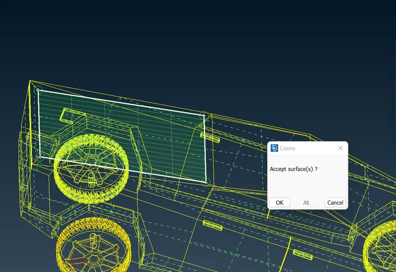
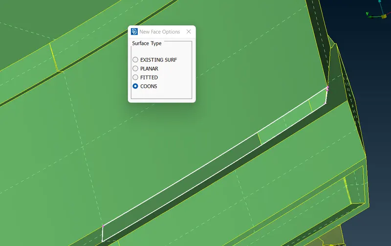
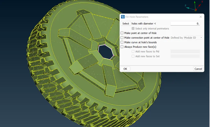
Filling the hole using fill hole
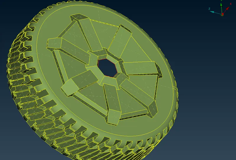
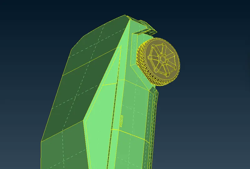
We see that tyres are not part of the vehicle volume
So we have the closed volume for the truck which is considered as 1, 2 we have separated volumes for tyres and then we create the wind tunnel volume between the truck and the wind tunnel
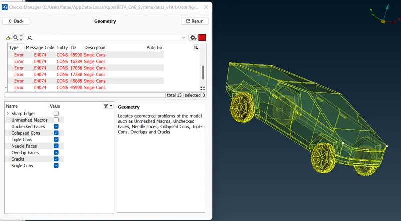
Now checking the geometry for the model using 'geometry checks'
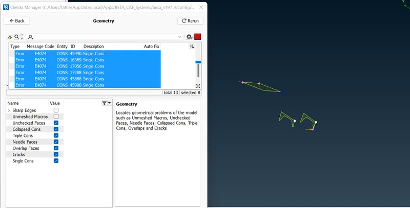
Fixing the above shown errors
Using topo to check will it fix the single cons
Now we see two single cons with some triple cons
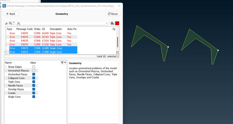
Now again checking geometry checks after eliminating errors
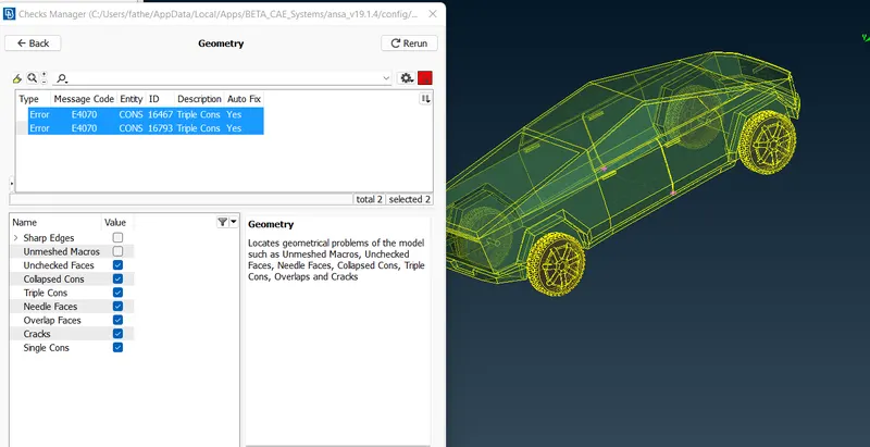
we see two triple cons which are acceptable where three surfaces are joining
Assigning the PIDs for the model as follows
For windows
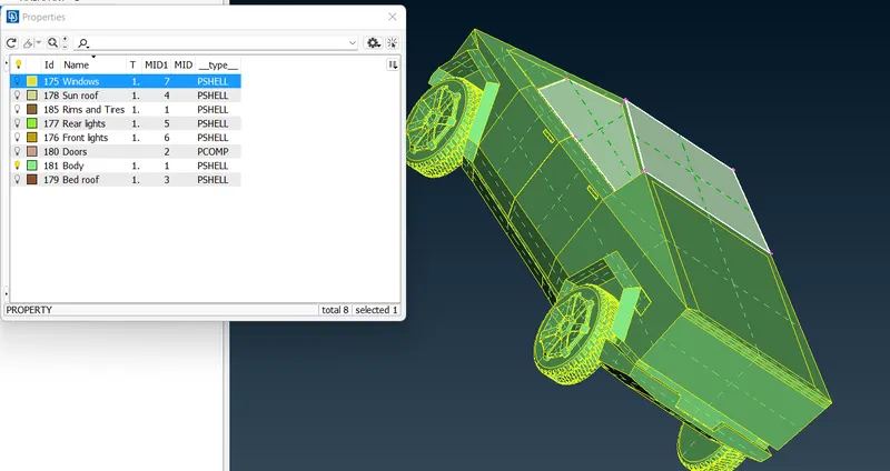
For sunroof
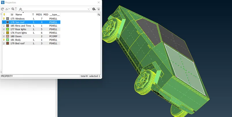
For tyres and rims
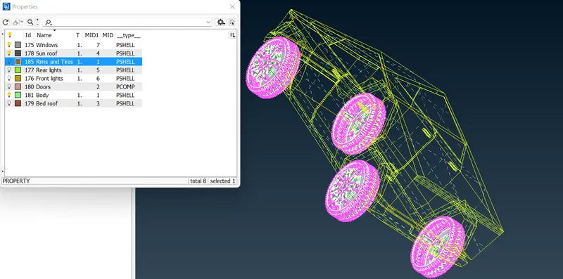
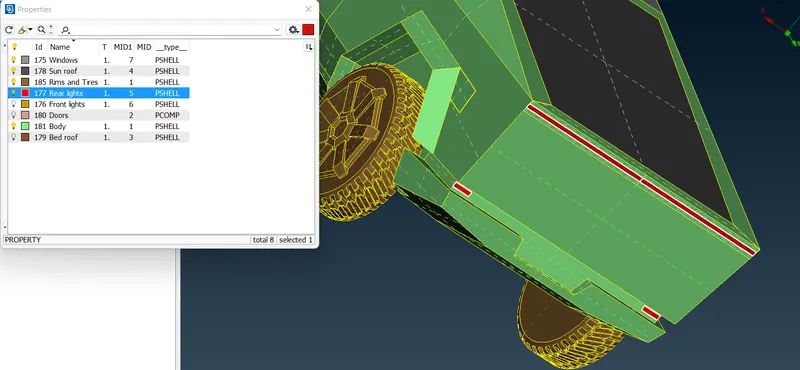
For rear lights
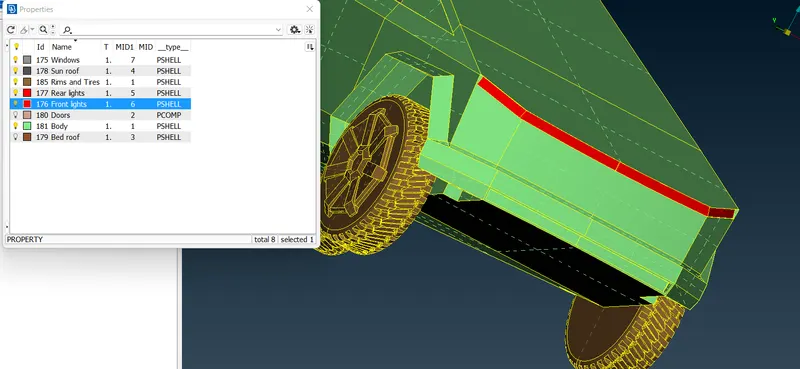
For front lights
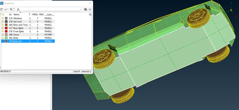
For bed roof
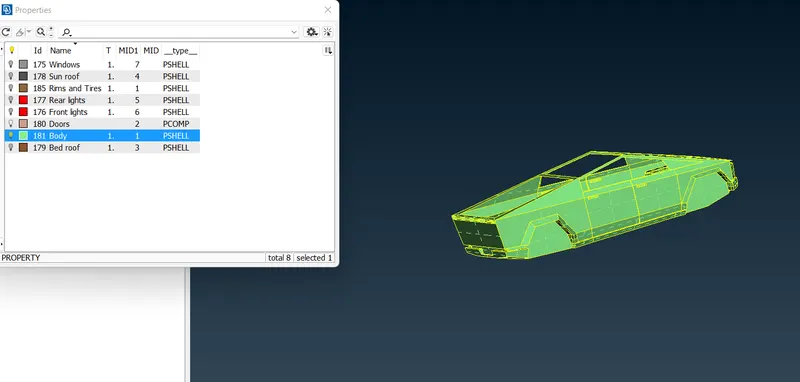
For body
MESHING
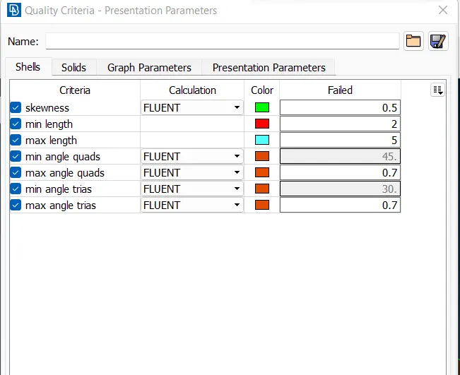
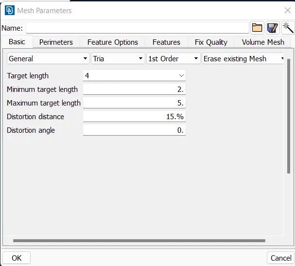
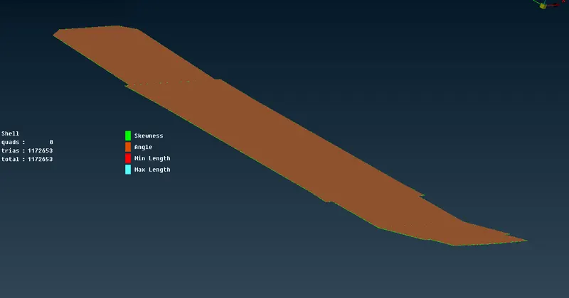
Giving quality criteria for the bedroof as follows and with target length of 4mm
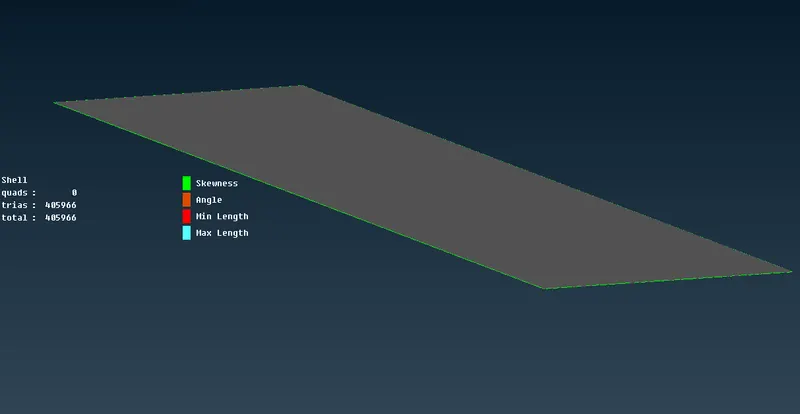
For sun roof with target length 4mm
For tyres and rims with target length 3mm
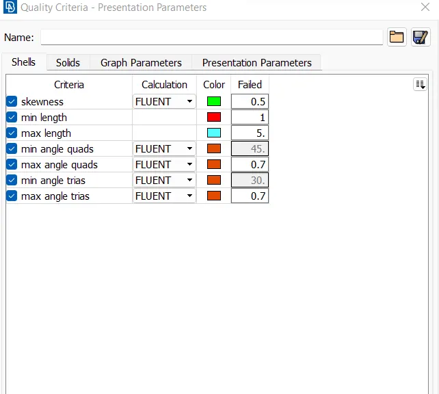
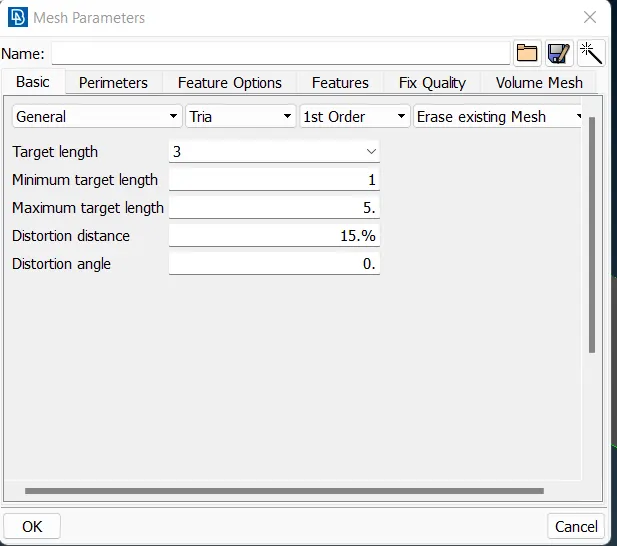
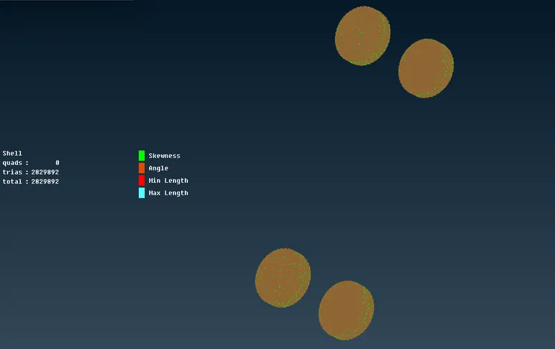
For rear and front lights with 3mm target length
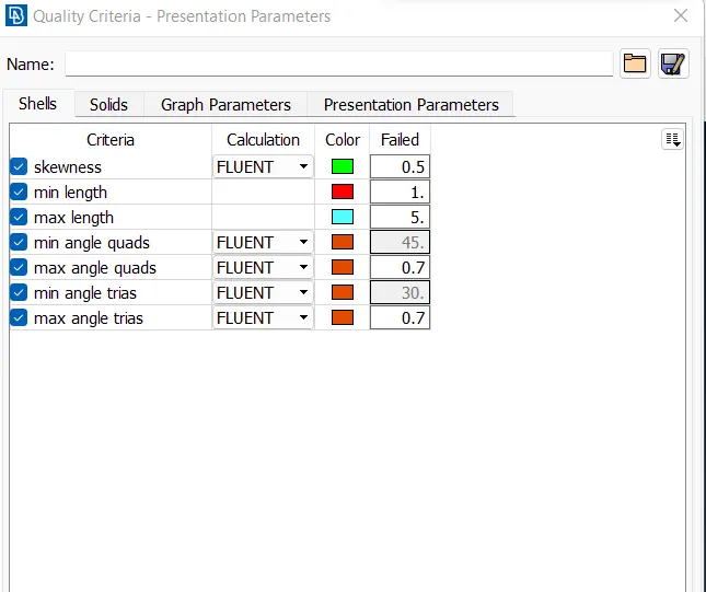
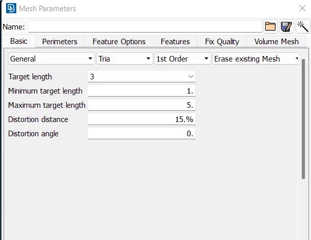
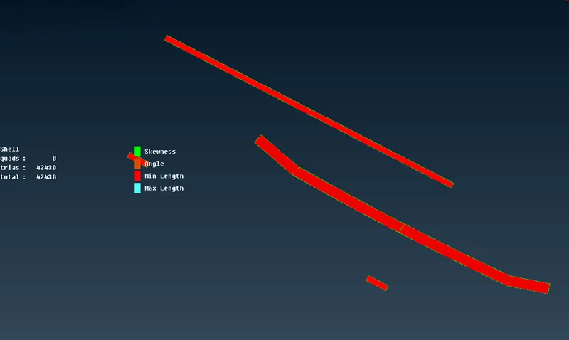
For windows with 5mm target length
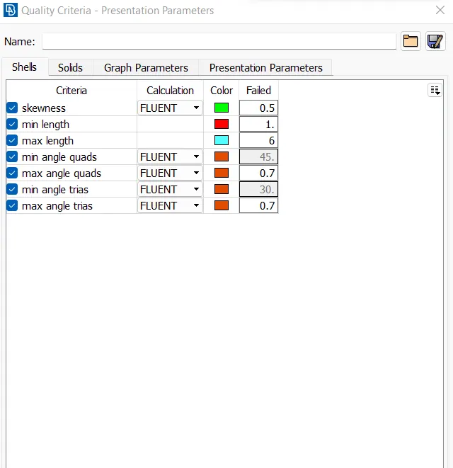
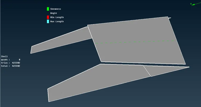
For body with 4mm target length
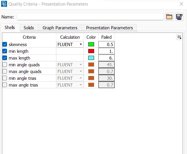
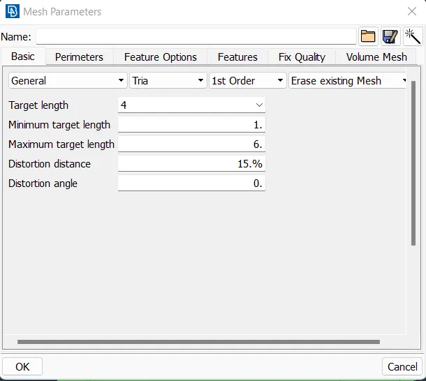
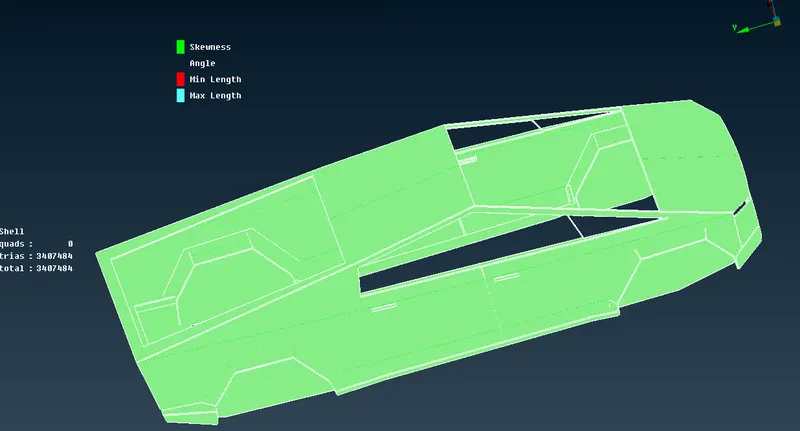
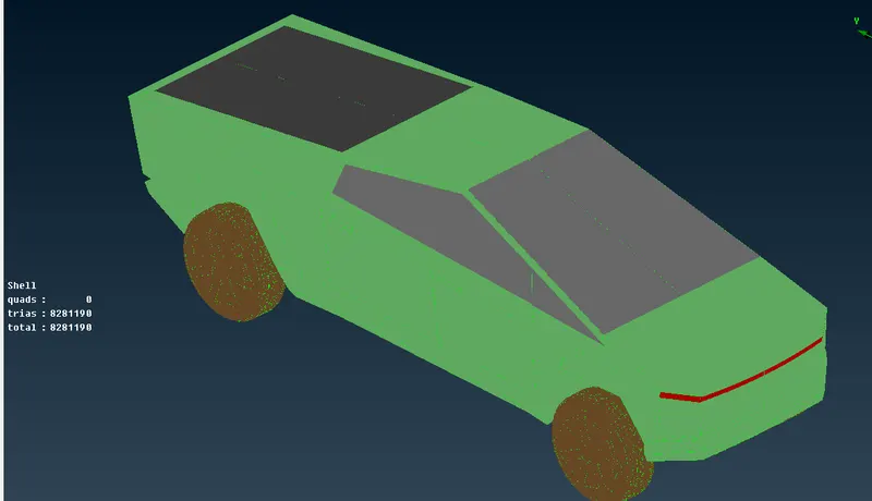
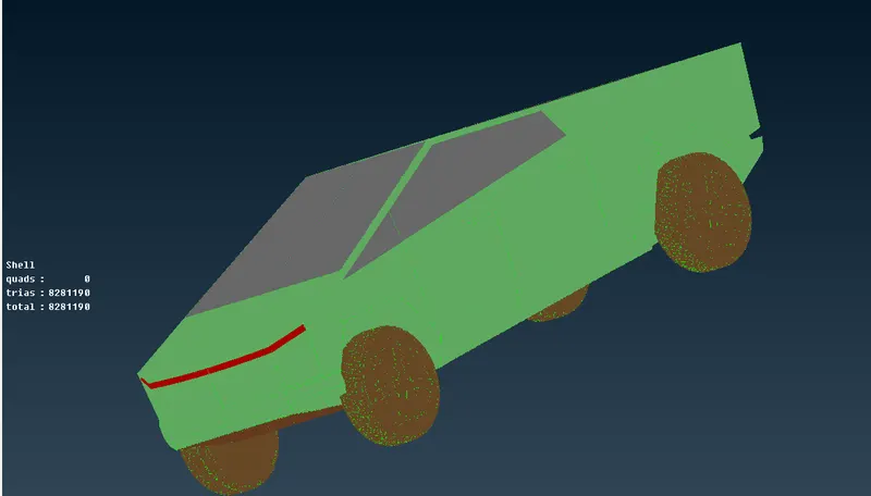
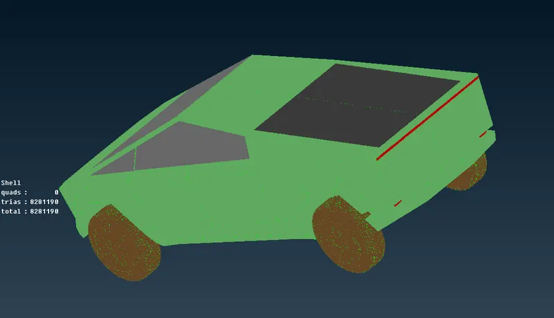
The complete mesh for the model looks as follows
WIND TUNNEL CREATION:
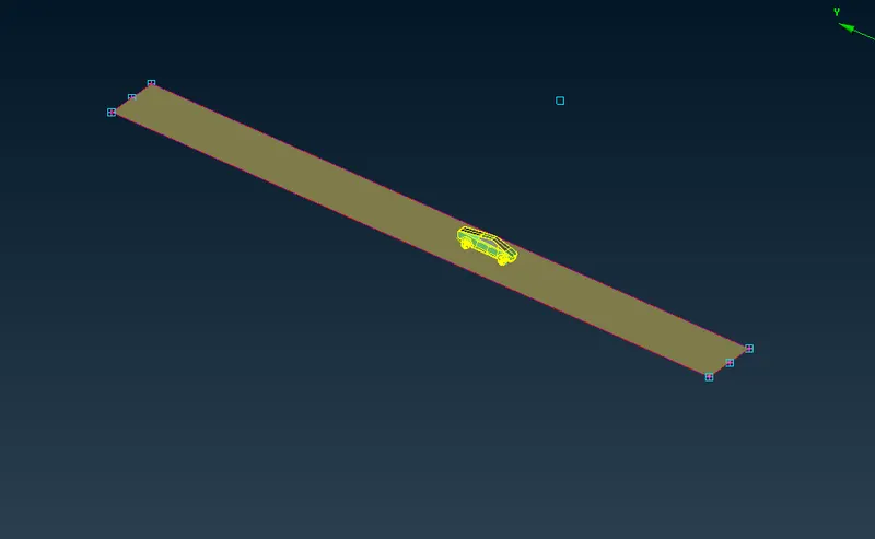
Now creating the wind tunnel
Measuring distance between two extreme nodes
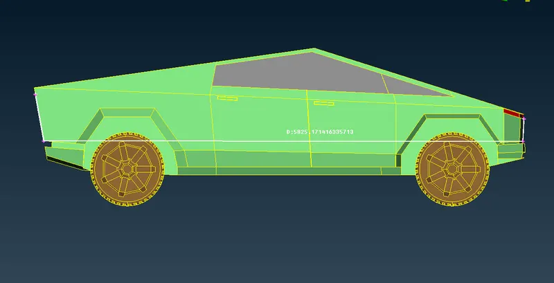
Its approx 5825mm
So front end of wind tunnel should be 4X distance from front node
for rear face of wind tunnel should be 6X distance from rear node
for top face 3X and bottom face near to wheels with some gap
side faces from top view to be X distance
creating a point at bottom of truck as follows with 400mm in -ve z-direction i.e bottom
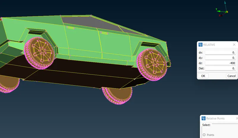
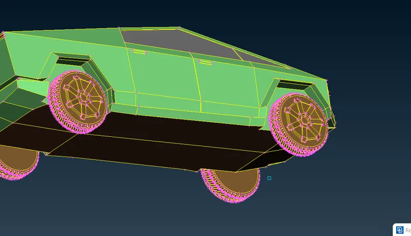
now making at point at front end to make 4X from there as follows i.e (4x5825)+890 =24190mm from point created
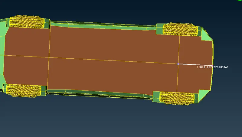
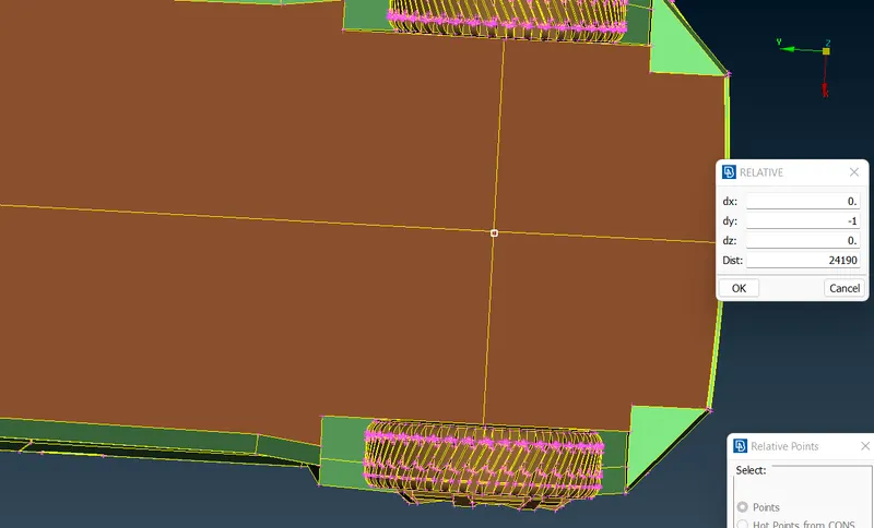
The point is created as follows

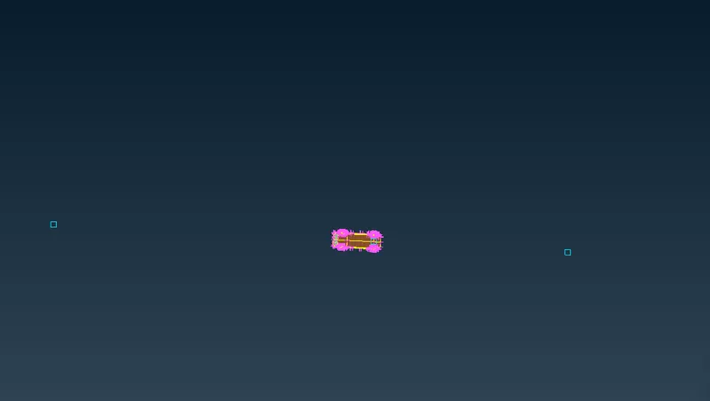
Now for rear side at 6X distance 6x5825+4905=39855mm to rear side
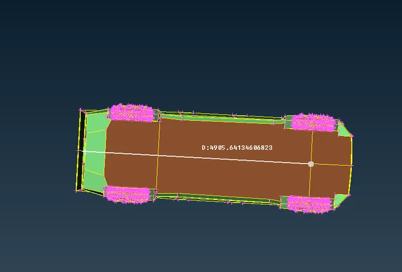
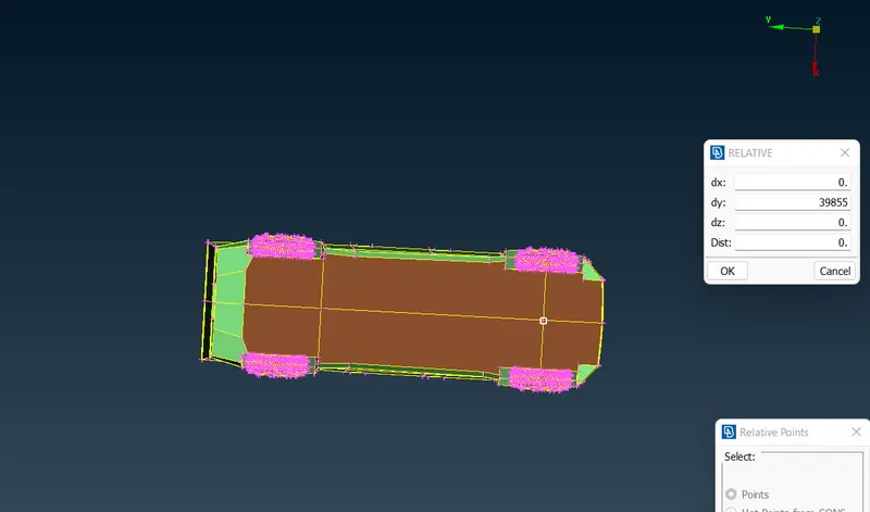
It is created as follows
Now for top end with 3X i.e 3x5825=17475mm to top
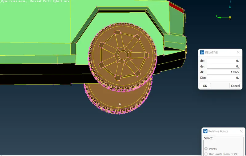
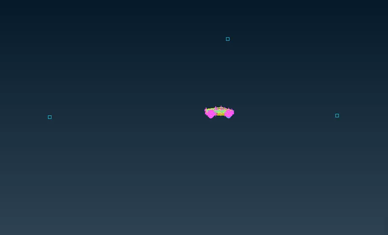
Now for side faces of wind tunnel with x diatance i.e 5825mm
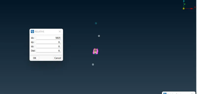
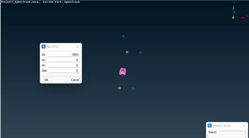
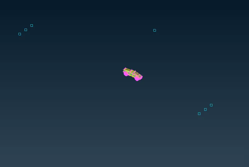
Using curves>create to create the bottom surface of wind tunnel
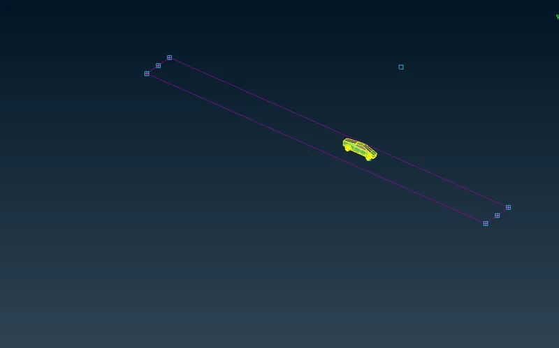
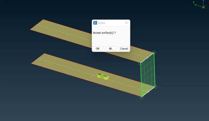
then using New>COONS to create surface
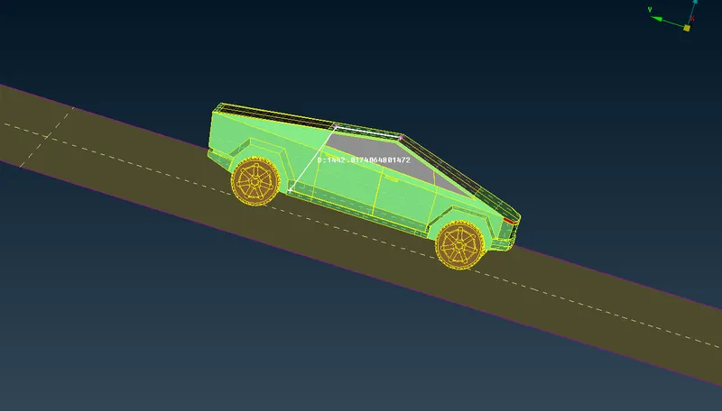
Measuring vertical distance of the truck is 1442mm
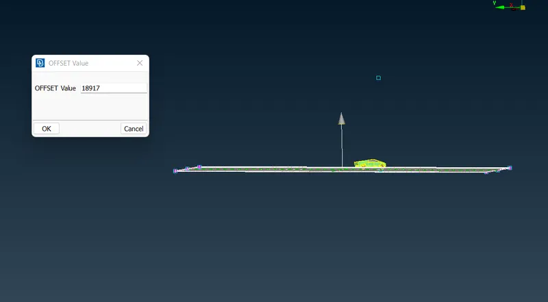
so top tunnel face with 3x5825+1442=18917mm
Using faces>offset
Creating other surfaces as follows
Assigning PIDs for tunnel
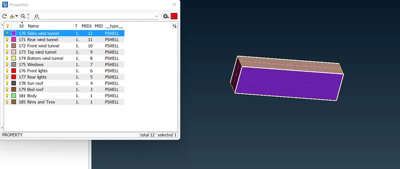
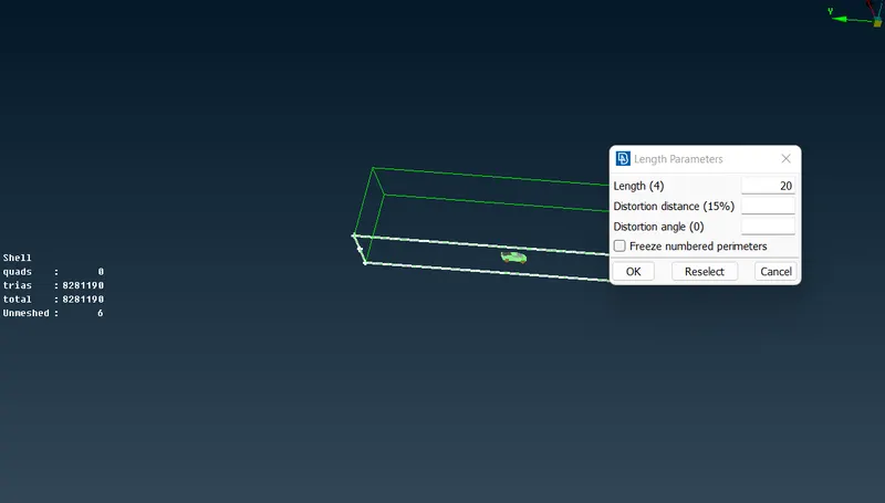
Now meshing
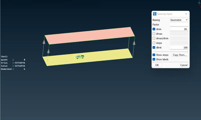
Top surface with 100mm and bottom surface with 20mm
Using spacing tool
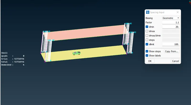
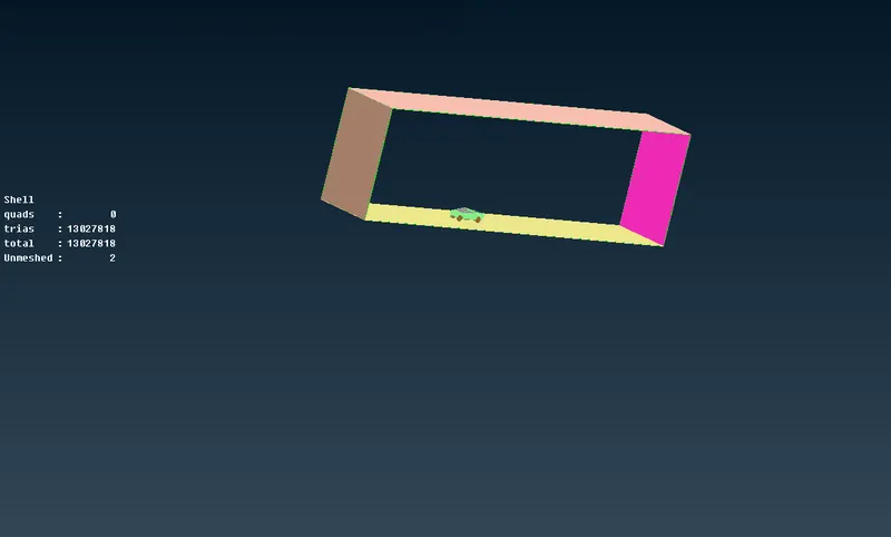
So meshing for the wind tunnel along with model is generated
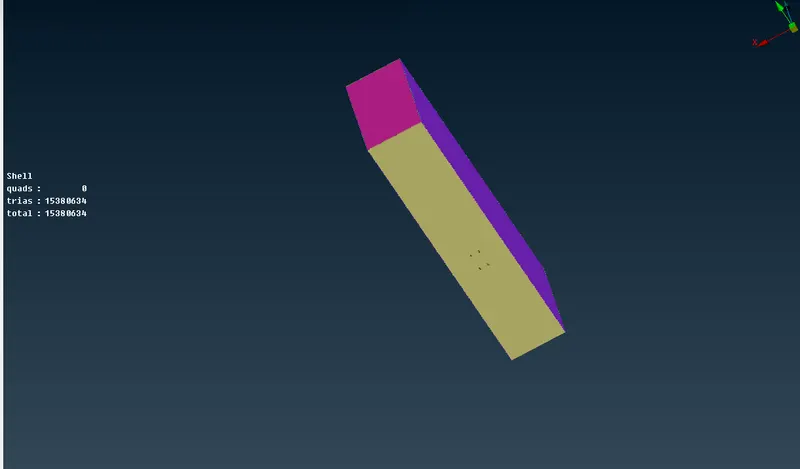
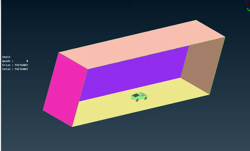
VOLUMETRIC MESHING:
Now doing the volumetric meshing for wind tunnel
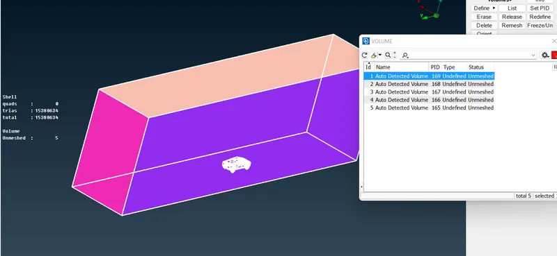
we only need the volume between model and tunnel, so checking for it and deleting the other volumes.
so this is the below volume which we basically need
TOOLS USED:
- Faces>New>COONS tool to make the surface
- Curve2Con to fix the con location
- Cons>cut to create the cut or to delete the cuts in model
- Hotpoints> multi-Project to project the hot point on the face required
- Fine tool > to make the model finer in geometry
- Mesh>Length>perimeter to give length for perimeters for meshing
- Mesh>Length>macros to give length for macros/faces for meshing
- meshing>spacing to give varying length mesh size
- Mesh>Reconstruct> To rearrange the elements in the meshing and avoid the skewness, min length, max length errors
- Topo>faces>Project cut> to cut the surface in 90 degrees from hotpoint to con
- Topo>relative point To create the point in the space at in any direction
- Mesh>Spot Mesh tool to mesh the visible on screen/ with select option
- Mesh>move grids to resolve the skewness, Min length, Max length errors.
- Topo>Release to release the con into single cons
- Topo tool to make the two surface double con/ three surface into triple con
THINGS LEARNED:
- Learned how to perform the topo/geometry clean up for the mode.
- How to eliminate the con erros.
- How to assign the PIDs required.
- How to mesh for different components with different target lengths.
- How to perform the volumetric mesh.
CONCLUSION:
Thus the surface mesh with Tria elements for the model and the wind tunnel has been generated successfully.
FILE LINK
https://drive.google.com/file/d/1EqotfJB3Ur_WdTbkW1J3DUns-ngAWqg4/view?usp=sharing