Project 1 : CFD Meshing for Tesla Cyber Truck
MESHING ON TESLA CYBER TRUCK
AIM: Perform meshing with the suitable Target length for cyber truck model.
OBJECTIVES:
For the given model we used suitable target length as 5mm for all part of model with different PID’s and with different quality criteria.
INTRODUCTION:
In this project we used the Tesla cyber truck model to mesh on it and we used to some tool and followed some steps to mesh the model.
Import Geometry/Model --- TOPO cleanup --- Patch the Error places --- Apply the PID’s --- Mesh each part of model with suitable mesh length --- clear off elements --- Create wind tunnel --- Apply PID’s to faces --- mesh the wind tunnel --- volumetric mesh (if possible) --- end.
PROCEDURE/STEP TO MESHING THE MODEL:
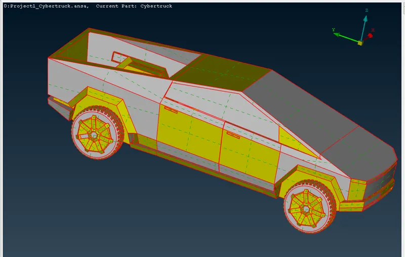
Import the Geometry is the first thing from sources. Then need to apply TOPO for full model to convert the single cons to double cons of model. The below image says the imported model.
Imported Geometry:
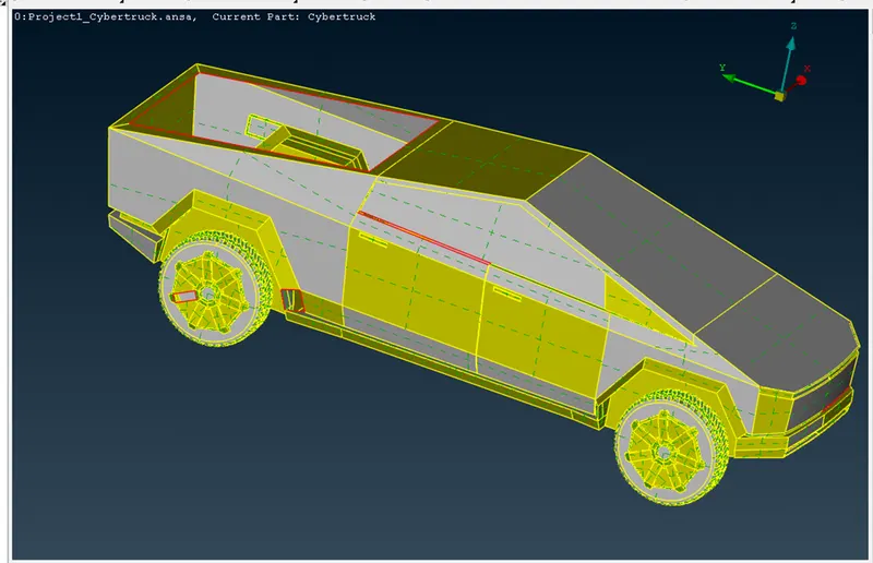
After apply of TOPO to model we need to identify the patches, single cons, triple cons and we need to apply the mesh on outer body of the model. The below image shows the TOPO applied model and highlights the errors.
Topo applied model:
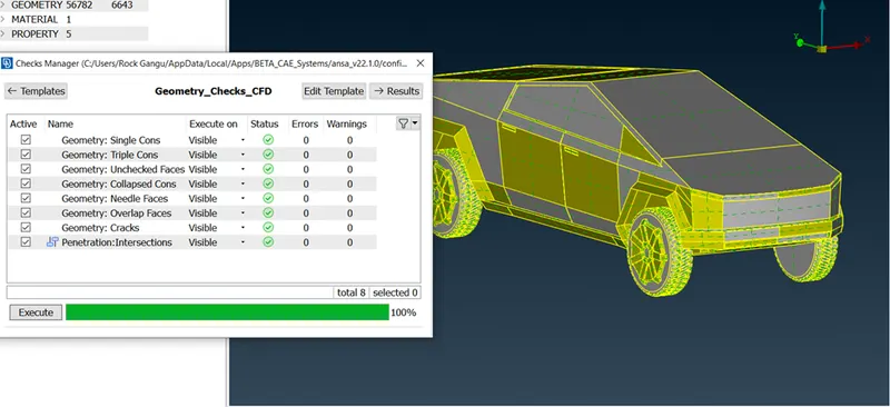
Now we need to patch the gaps and make the single con to double con. Coz single con is a error for the meshing process. Here we used the New (to fill holes and patches). The below image is the window of TOPO cleared the geometry.
TOPO cleaned up Geometry/Model:
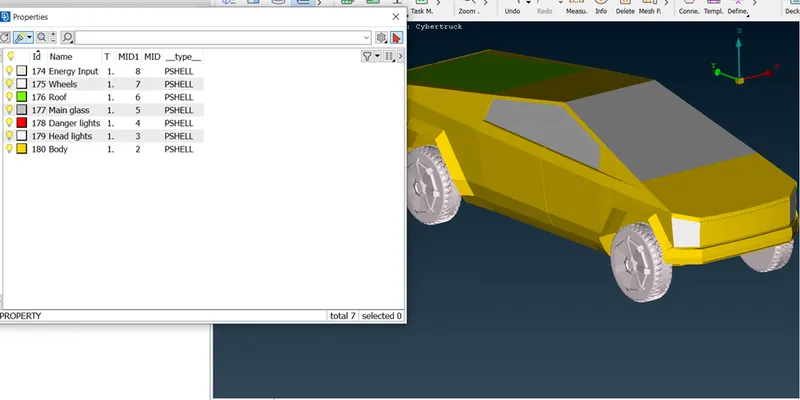
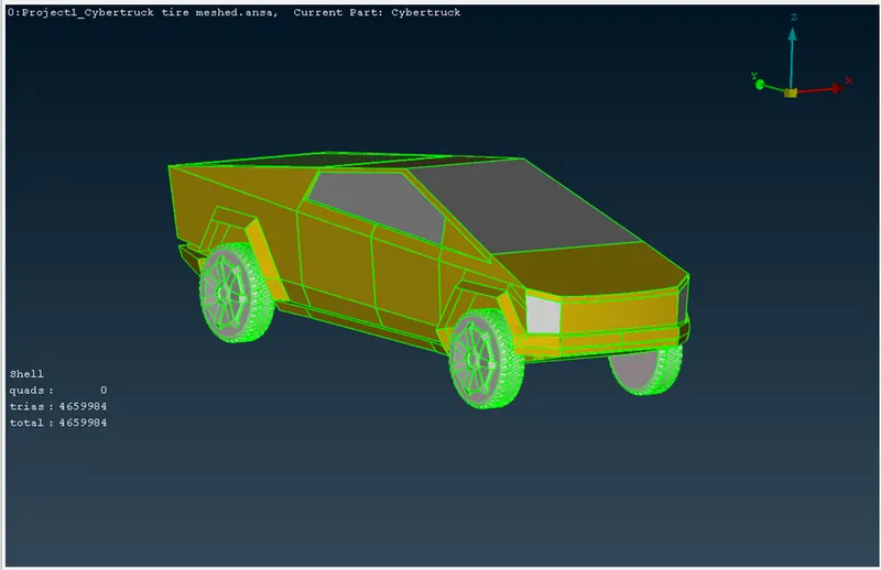
Once we cleared the TOPO/ errors in model we need to apply the PID’s to the model. In below image we can see the PID’s and PID applied parts of model.
PID applied cyber truck model:
Back view of model:
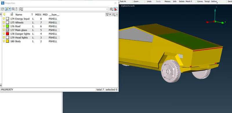
After PID application we move towards meshing section. Here we need to select the target length and need to set the quality criteria for the mesh. After some measure check of small areas of part, we decided to set the target length for the parts as
Length of mesh table:
|
Part name |
Target length |
Min. length |
Max. length |
Skewness |
|
Head light |
5 mm |
3 mm |
7mm |
0.5 |
|
Danger (back) light |
5 mm |
3 mm |
7 mm |
0.5 |
|
Main glass (Mirror) |
5 mm |
3 mm |
7 mm |
0.5 |
|
Roof |
5 mm |
3 mm |
7 mm |
0.5 |
|
Energy inlet (Tank input) |
5 mm |
3 mm |
7 mm |
0.5 |
|
Wheels |
3 mm |
0.5 mm |
7 mm |
0.5 |
|
Body |
5 mm |
1 mm |
7 mm |
0.5 |
Now we need to apply the mesh for each part separately to avoid the mesh crack/overlap of mesh. Before apply the spot mesh we need to set the perimeter and macro as target length value. And we need to do the meshing process in hidden mode to see the off element of mesh.
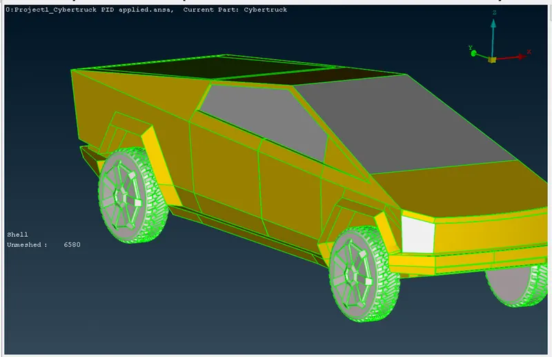
If the part is having the off element on body then make the off elements as 0 by reconstruct option or we can solve it by manually using move option. Which is helps to set the mesh in quality criteria and we need to freeze the part after meshing to avoid the overlap of mesh. The below image shows the meshing of each part.
Cyber truck mode for meshing:
Meshed wheels:
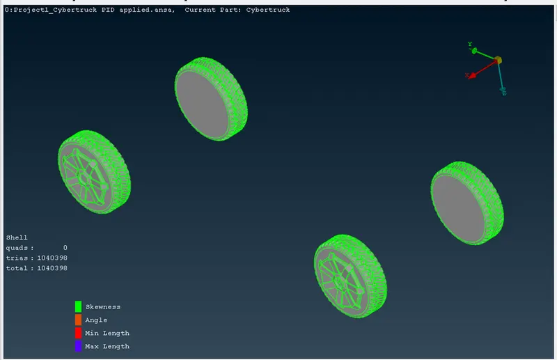
In below image we can see that the wheels of model are completely meshed with given quality criteria. During meshing we get some off elements on wheels the we used the reconstruct tool to set mesh in quality criteria. And for some off elements used the move tool to fit the meshes in particular size manner of quality criteria. After meshing complete on wheels we get the elements in total as 1040398. After completion we freeze the part.
Roof mesh:
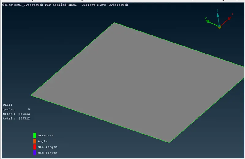
Now we selected the Roof part for meshing from PID list and we used show only option to mesh the roof pat. We need to change the quality criteria as per the mesh length table. Then set the perimeter and macros as per the criteria and apply the spot mesh. After spot mesh we got some off elements and we reconstructed them and made them o off elements and we got the total elements as 259512. After completion of meshing freeze the part.
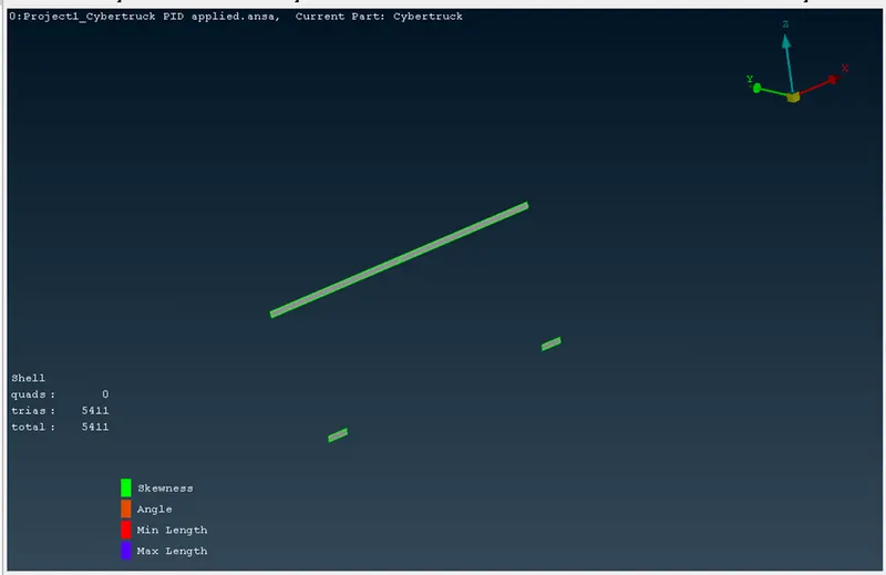
Back/Danger light:
Now we selected the Back/danger light part for meshing from PID list and we used show only option to mesh the Back/danger light pat. We need to change the quality criteria as per the mesh length table. Then set the perimeter and macros as per the criteria and apply the spot mesh. After spot mesh we got some off elements and we reconstructed them and made them o off elements and we got the total elements as 5411. After completion of meshing freeze the part.
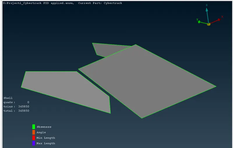
Mesh of Main Glass/Mirror:
Now we selected the Mirror part for meshing from PID list and we used show only option to mesh the Mirror pat. We need to change the quality criteria as per the mesh length table. Then set the perimeter and macros as per the criteria and apply the spot mesh. After spot mesh we got some off elements and we reconstructed them and made them o off elements and we got the total elements as 365850. After completion of meshing freeze the part.
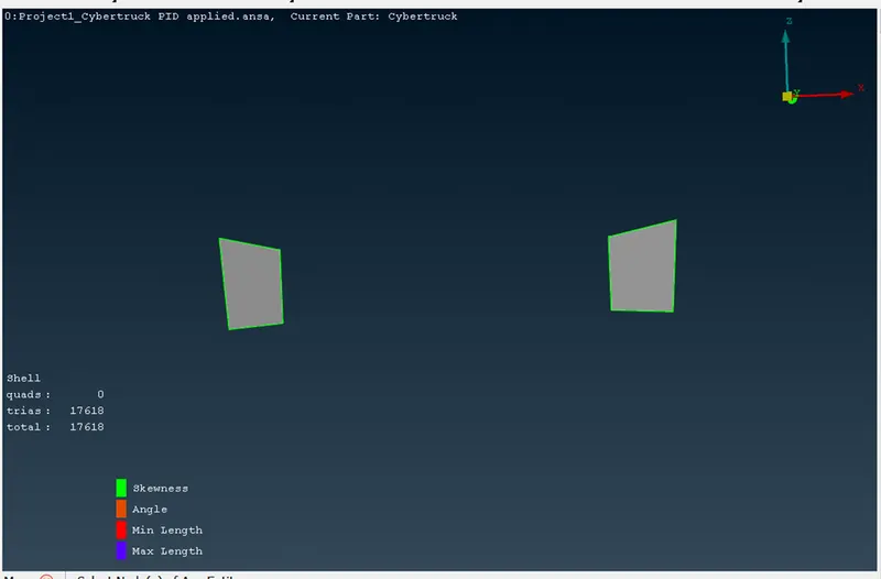
Meshed head light:
Now we selected the Head light part for meshing from PID list and we used show only option to mesh the Head light pat. We need to change the quality criteria as per the mesh length table. Then set the perimeter and macros as per the criteria and apply the spot mesh. After spot mesh we got some off elements and we reconstructed them and made them o off elements and we got the total elements as 17618. After completion of meshing freeze the part.
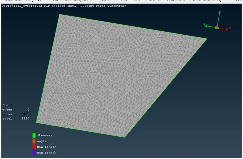
Meshing Energy inlet:
Now we selected the Energy inlet part for meshing from PID list and we used show only option to mesh the Energy inlet pat. We need to change the quality criteria as per the mesh length table. Then set the perimeter and macros as per the criteria and apply the spot mesh. After spot mesh we got some off elements and we reconstructed them and made them o off elements and we got the total elements as 2820. After completion of meshing freeze the part.
Meshing of Body part:
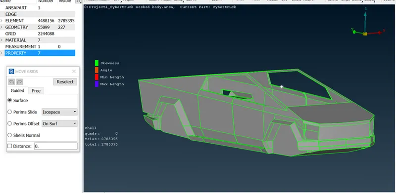
Now we selected the Body part for meshing from PID list and we used show only option to mesh the Body pat. We need to change the quality criteria as per the mesh length table. Then set the perimeter and macros as per the criteria and apply the spot mesh. After spot mesh we got some off elements and we reconstructed them and made them o off elements and we got the total elements as 2785395. After completion of meshing freeze the part.
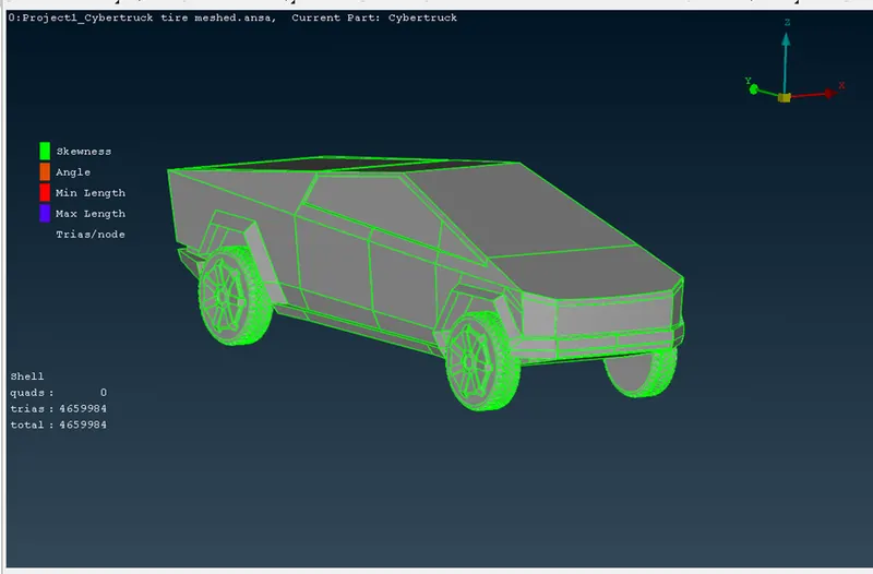
The below image shows the completely cleared off elements with 4659984 elements.
All cleared off elements:
The cyber truck model with applied PID’s:
After completion of meshing on model we need to create the wind tunnel around the model.
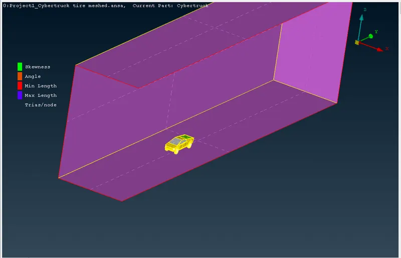
We used the Relative tool to identify and make dimensions of wind tunnel. We created the point under the model from that point we can give dimensions of wind tunnel. We can allow the faces of wind tunnel in the range of, for front face 4x of model, for rear face 6x of model, for top face 3x of model and for side faces 1x of model. Here x is the length of the model.
After creation of relative points we need to create the faces of six and close the model with wind tunnel. For creation of faces we need use the curve tool to create the line using the relative points. The image shows the wind tunnel creation around the model.
Wind Tunnel creation around the model:
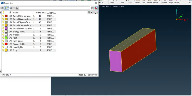
After creation of wind tunnel we need to Apply the PID’s to the all faces of tunnel. Coz to allow the mesh face by face to get the good mesh.
PID applied Wind tunnel:
PID applied Wind Tunnel with Model:
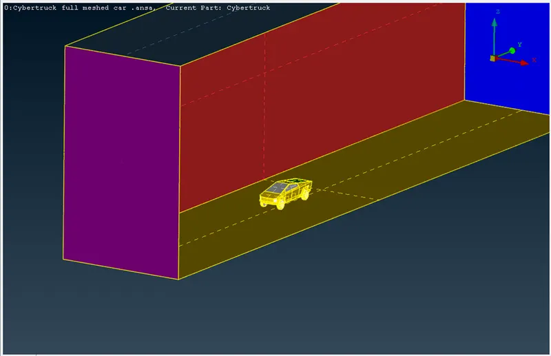
After PID application we need to apply the mesh to wind tunnel. We need to care about the model, so we need to create the mesh at base surface of less length of mesh size and for other surface we give the mesh length as more or higher.
By considering this we give the base surface mesh as 20mm target length and 100mm target length for top surface. Coz the base surface mesh can effect on model, so we used the lesser mesh length. For other faces we used the spacing tool to create the mesh from lower to higher size. In spacing we gave the factor as 1.1 and target of 20 to 100mm from base to top surface of tunnel. And before applying the mesh we need to confirm the direction of spacing of mesh. Then allow spot mesh by each respected surface one by one to avoid the more time of action of mesh application.
Meshed Wind Tunnel body:

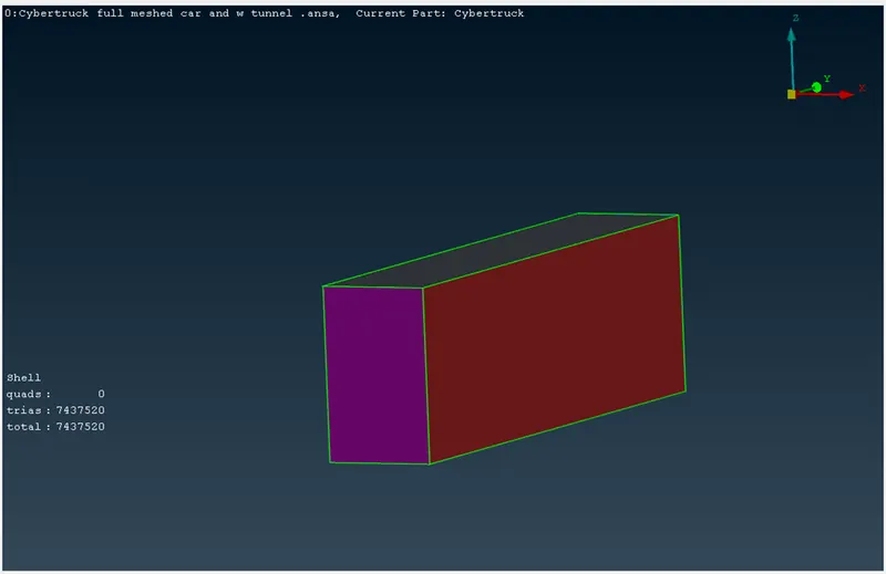
We got the elements of 7437520 elements by meshing the wind tunnel.
ANSA MODEL OF CYBER TRUCK AND WIND TUNNEL:
https://drive.google.com/file/d/1ApFDDJMMl2sTVuKGiNWDClFKv_SjGfjX/view?usp=share_link
After meshing the tunnel, we move to volumetric mesh.
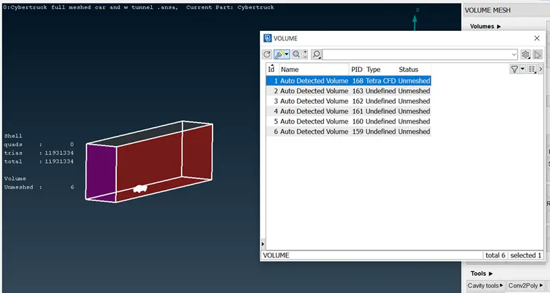
In volumetric mesh select define for whole database, the volume of model will create automatically and get the list as below.
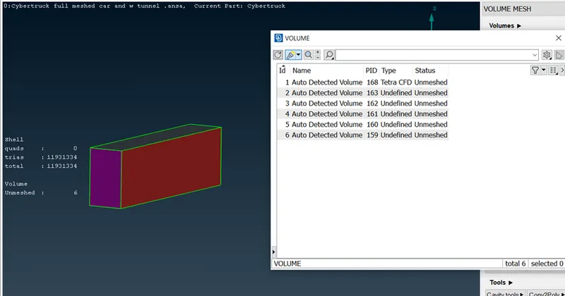
Then we need to delete the other volume rather than one volume i.e., one volume of model and wind tunnel. We need to perform the volumetric mesh on one volume.
The below image shows the volume the we have perform the volumetric mesh on the particular volume.
Selected volume for volumetric mesh:
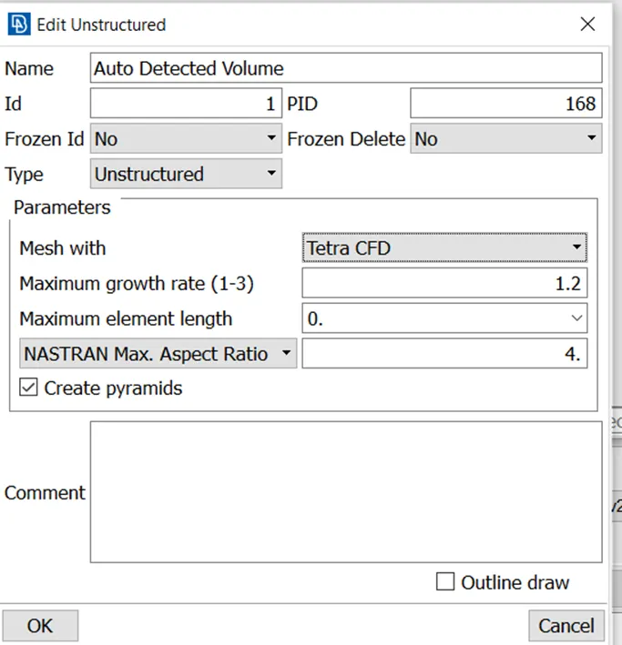
Details of tetra CFD mesh:
LEARNING OUTCOMES:
From this project we learnt TOPO cleanup, PID allocation, Classic mesh on model for each part, wind tunnel modelling and volumetric mesh.
RESULTS AND OBSERVATIONS:
From the meshing of cyber truck model, we get the elements of 4659984 and from wind tunnel we get the elements of 7437520 and from both components we get the elements of 1193134.
In this project the volumetric mesh is incomplete by some disadvantage of storage of system.
From this project we observe that the meshing time is increases when we allow the less mesh size for model. The length of the model is also larger and we decided to take the mesh size as 5mm. For body meshing and wind tunnel meshing ANSA took more time for mesh. During volumetric mesh the ANSA cracked twice coz of millions of elements and problem with storage.
CONCLUSION:
From above observations we conclude that the larger model like cyber truck also performed for meshing with lot of elements. The meshing on Cyber Truck model of classic mesh is performed with high number of elements. For larger model need more storage space and time to get the volumetric mesh.