Project 1 : CFD Meshing for Tesla Cyber Truck
Objective :
- To identify & clean up all the topological errors in the given Tesla Cyber Truck Car model.
- To create a surface mesh.
- To Create a wind tunnel around Tesla Cyber Truck Car.
- To create a volumetric mesh to perform an external flow CFD analysis simulation.
Introduction :
ANSA :
- ANSA is a Computer-aided engineering tool for Finite Element Analysis and CFD Analysis widely used in the automotive industry. It is developed by BETA CAE Systems. The software is distributed worldwide by a number of BETA CAE Systems subsidiaries and business agents.
- ANSA maintains the association between CAD geometry and the FE mesh. This means that the FE meshes are better representations of their geometric parents. Also, it is easy to maintain and update any changes in the geometry by simply reworking the updated area instead of recreating the FE from scratch.
- It carries several proprietary algorithms for meshing suitable for both CFD and structural models. ANSA was initially standing for 'Automatic net generation for structural analysis, but the software has gone beyond that very quickly. ANSA has broadly six menus that are used to do various activities those are: TOPO MESH, VMESH, DECK-SOLVER, MORPH, and BLOCK.
Different type of modules in ANSA :
- TOPO - Set of tools for Geometry clean-up and for setting up of PIDs.
- MESH - Tools to generate Surface Mesh or 2D Mesh.
- VOLUME MESH - To generate solid or 3D Mesh.
- SOLVER DECKS - Tools based on different solvers such as ABAQUS, RADIOSS, ANSYS, etc.
- MORPH - Advanced tool to capture geometry more accurately while meshing.
Solution procedure :
- For solving we follow the below procedure,
- Import the CAD model.
- Identifying & cleanup up the topological / geometry errors.
- Geometry check-up.
- Setting up of relevant PIDs.
- Defining the element size or length.
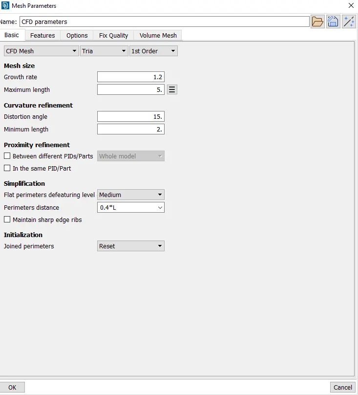
- Setting the mesh parameters, selecting of meshing type, and generating a surface mesh of the CAD model.
- Resolving the errors in the surface mesh.
- Creating the wind tunnel for external flow CFD analysis and surface mesh of the wind tunnel.
- Generating volumetric mesh.
- Let us start solving one by one by following the above steps :
1) Importing CAD the model :
- To import the CAD model we follow below steps,
Go to file -> open -> browse the location of the CAD model -> select it and click on open.
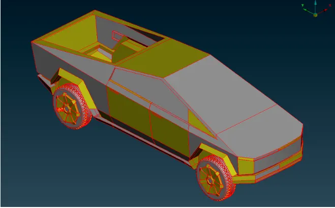
- In the above image we can see only single cons, let us do topo for the whole model, then we can get a clear idea of the model and actual single cons. In the below image, you can see the model after performing the topo.
- Single cons are deleted by adding new faces, topo options
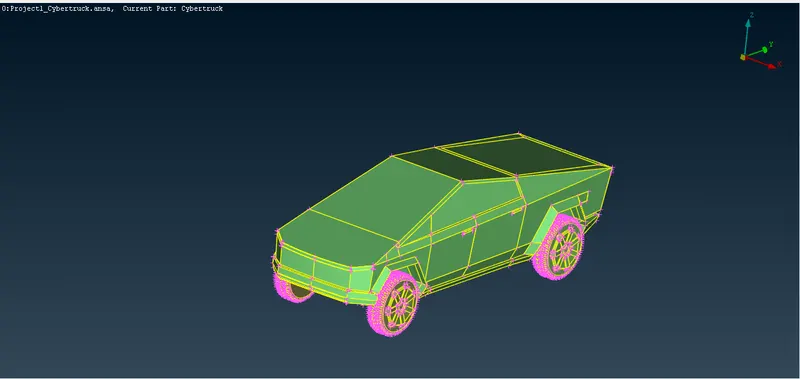
2) Identifying & clean up the topological / geometry errors :
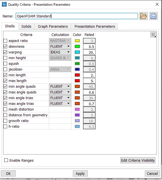
- Before performing any topo cleanup to have a better resolution let us first go to the mesh deck and decrease the mesh length by selecting the whole model and giving a 1mm mesh length.
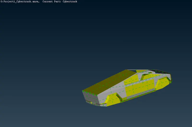
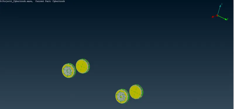
- the main aim is to create the whole car inside part as one volume, here tyres are inserted into the body but not attached . Here we can go with two approaches either we can delete the common extra part and perform topo and make the whole cars and tyres as one volume or we can delete the common part and close the holes such that only the car forms one volume and as tyres are not attached, then each of them forms one volume means 4 tyres 4 volumes. Here we follow the second approach it will be much better. And with these 5 volumes, another volume forms between the car and the wind tunnel, which is the volume we needed. So we delete all other volumes and keep the final volume as we are doing external flow analysis.
a) Body part :
Topo Clean up for body
b) Topo clean up for tyres :
3) Geometry check-up :
- After cleaning up all the topological errors, the geometry is checked using geometry checks under the checks manager.
- The below image is of the checks manager after performing geometry checks. We will see that no errors are present.
4) Create appropriate PIDs
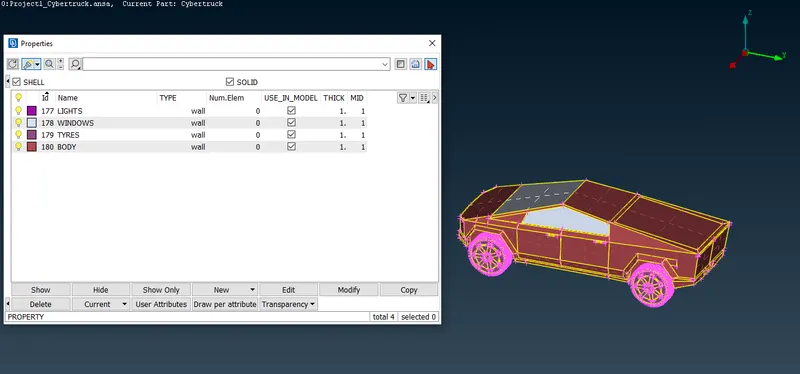
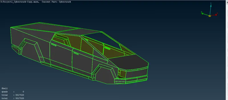
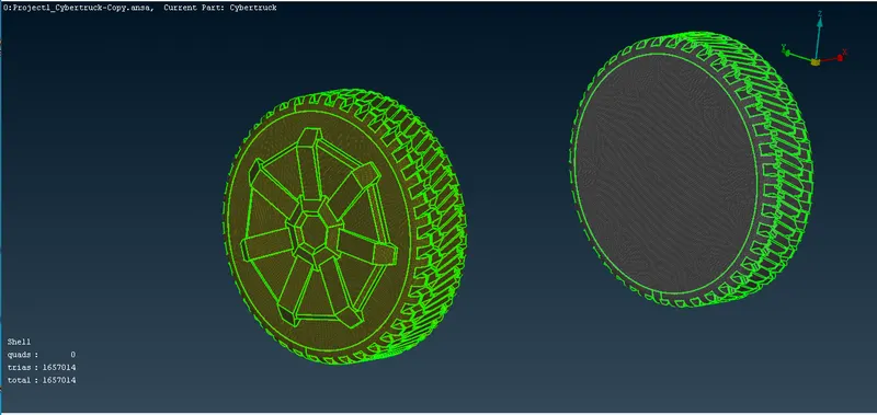
4) surface mesh
a) Parts: Windows
Mesh length= 2mm
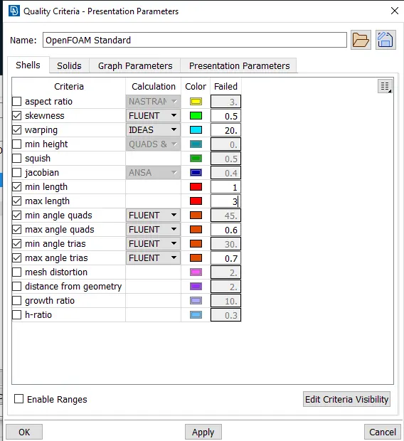
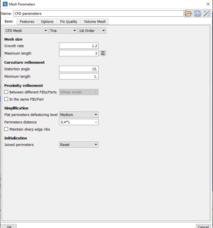
After spot meshing --> visible --> for windows part
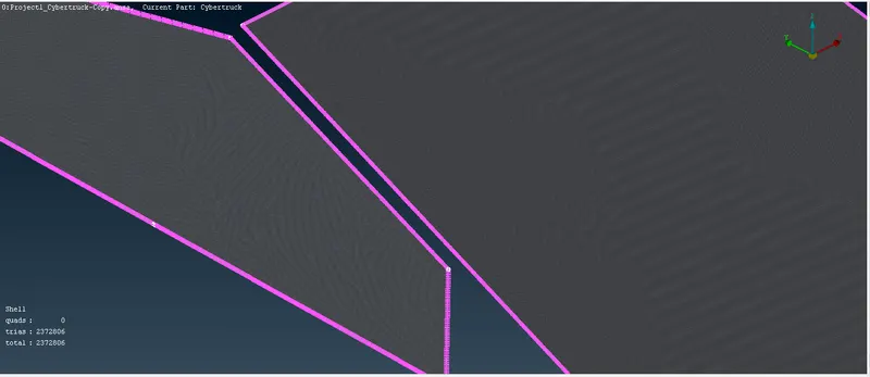
b) Parts: Tyres, body & lights
Mesh length= 4mm

5) Creating the wind tunnel for external flow CFD analysis and surface mesh of wind tunnel :
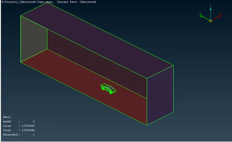
- To perform external flow CFD analysis a wind tunnel has to be created around the car. It is created in TOPO mode as a Rectangular box. The Dimensions of the wind tunnel is also important so as to capture the exact flow around car. The dimensions are as follows:
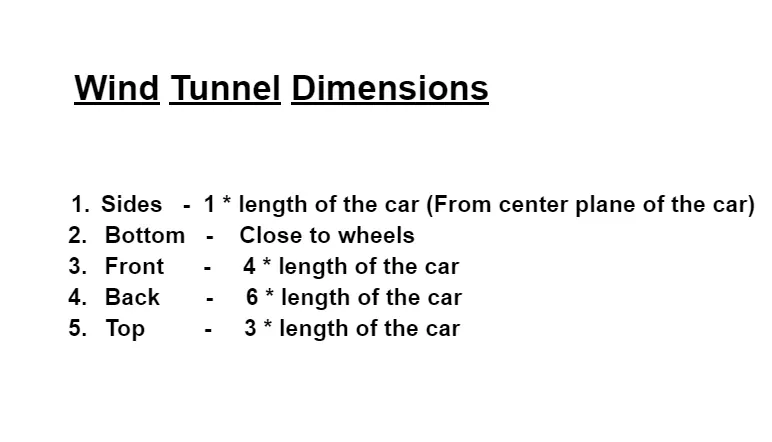
- In order to create a Wind tunnel, first create a point by selecting a relative at 650mm from the body to the bottom by selecting a hot point at a distance of 650 mm to the bottom.
- By taking that point as a reference, we create another point to the front of car at a distance of 4* 5700 = 22800 mm ( 5700 mm is the length of a car ).
- Then we create another point at the back at a distance of 5700 +6* 5700 = 39900 mm (5700 mm is length of car and as we create relative to front point we add 5700 mm more).
- Then we create another two points on both sides of car, with the help of front and back of car , which we have created , such that we can join all the four points with the help of curve and create a surface there with the help of 4 curves .This completes creation of bottom part .
- Then we create top face by using offset at a distance of 1900 + 3* 5700 = 19000 mm (1900 mm is distance from bottom to top of car and 5700 mm is length of car ).
- Now using these two surfaces we create new surfaces on all sides and close the volume , such that it forms a wind tunnel .
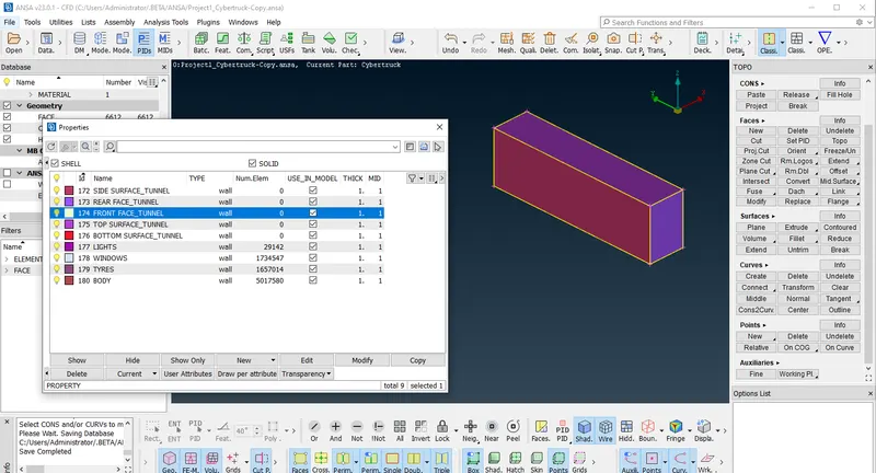
- Now we create and assign PID's for the wind tunnel walls.In the below image we can see that PID's are created and assigned .
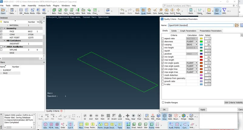
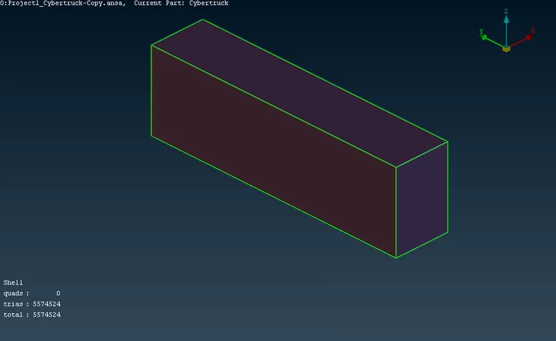
Meshing bottom surface of the wind tunnel
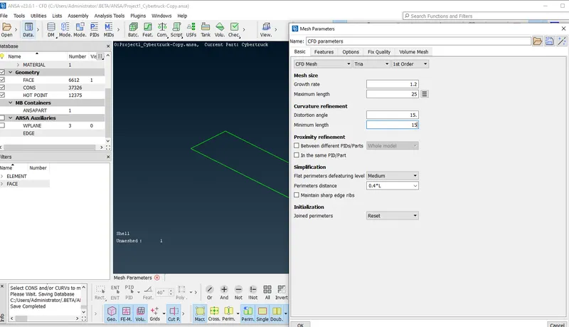
Meshing top surface of the wind tunnel
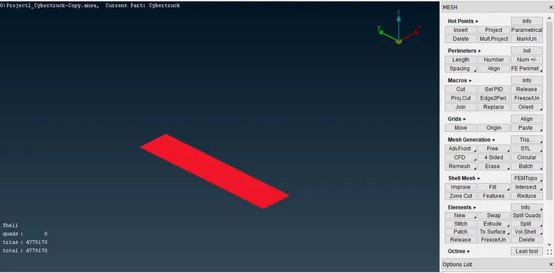
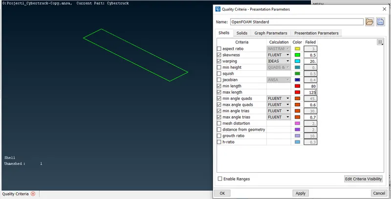
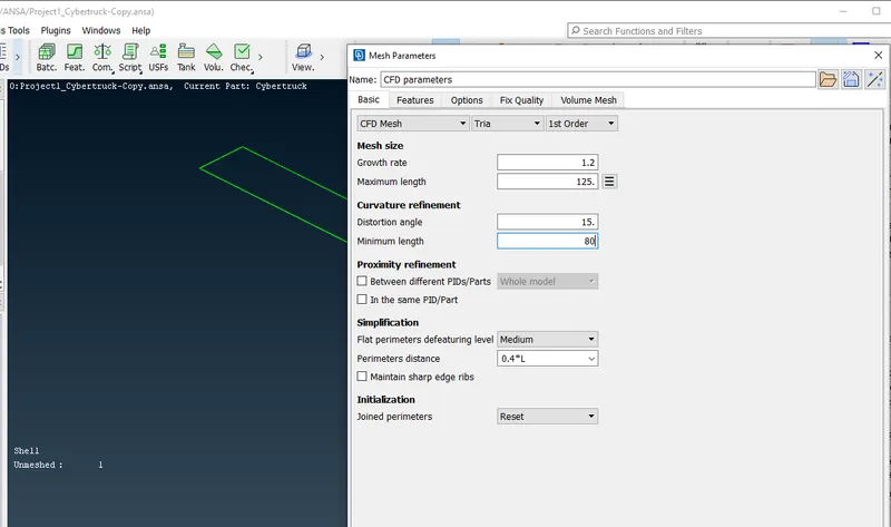
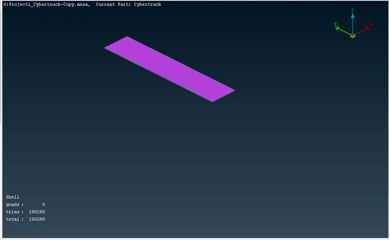
Meshing of side, front & Rear surfaces of the Wind tunnel
Conclusion :
- The imported CAD model of Tesla cyber truck is Topologically Cleaned & Corrected all the feasible surface errors to perform external aerodynamic analysis.
- Surface mesh is generated with the required element size.
- Reconstructed the mesh as per the mesh quality required at Corners & at the Intersection of edges.
- Worked with the errors occurred in the Mesh.
- Created a wind tunnel For external aerodynamic analysis.
https://drive.google.com/file/d/1fCyJfoXv8ZSkr-2ksdQrq48emL_SR7Sk/view?usp=share_link