Project 1 : CFD Meshing for Tesla Cyber Truck
AIM:
For the given tesla cybertruck model, check and solve all geometrical errors and Assign appropriate PIDs. Perform meshing with the suitable Target length and element Quality criteria.
Target lengths for the different parts of a model are as follow:
1.Body - 5 mm
2.Lights and indicators - 1 mm
3.Doors - 3 mm
4.Wheel and Tyres - 3 mm
5.Bumper and mudflap area - 3 mm
6.Windshield - 3 mm
7.Door gaps - 2 mm
OBJECTIVE:
- For the given Tesla cybertruck model, topo cleanup should be done.
- Surface meshing should be done in the given target lengths for each part
- A wind tunnel should be created and should be surface meshed.
(all elements should be tria and off elements should be zero)
PROCEDURE:
TOPOLOGICAL CLEANUP & PID ASSIGNING
General Procedure
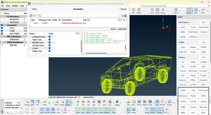
- Under checks- geometrical checks- template-ANSA[AUTO GENERATED TEMPLATE]-visible
- Found out several locations of single cons and filled with appropriate fills.
- In several locations during topo cleanup, intersect and faces where used to convert single cons.
- In some locations single cons were converted to triple cons by using TOPO.
- In curved locations, multiple hotpoints was created using parameteric option and connected by coons in faces.
- After topocleanup PIDs were assigned.
- It is necessary to fill all gaps for volumetric meshing. So fills where done to avoid leakage in CFD analysis.
- All PID’s name is given.
TOPO Cleanup of Tesla Cybertruck model
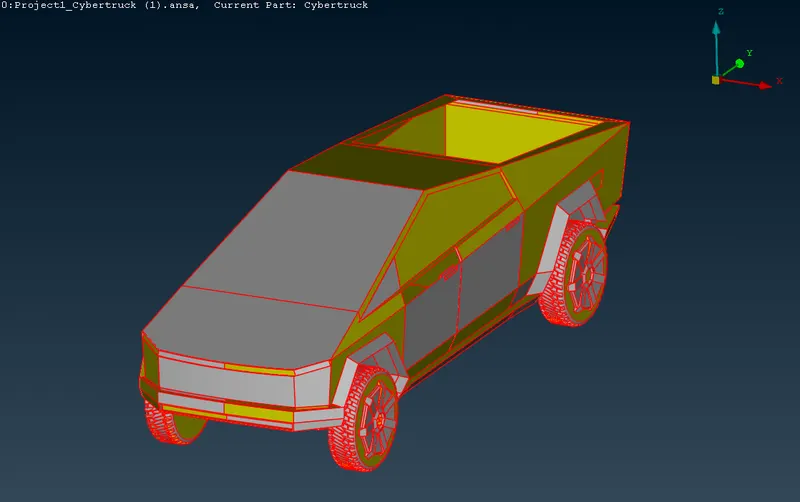
- The model is having geometric inaccuracies and shape changes in various locations in the body and the model is containing immense number of single cons even in double cons position. So to remove it all select the model and perform TOPO option to convert single cons to double cons.
- Now bring the model to Left view and for deleting half portion Project Cut from node in the middle of a con to next con along midplane.
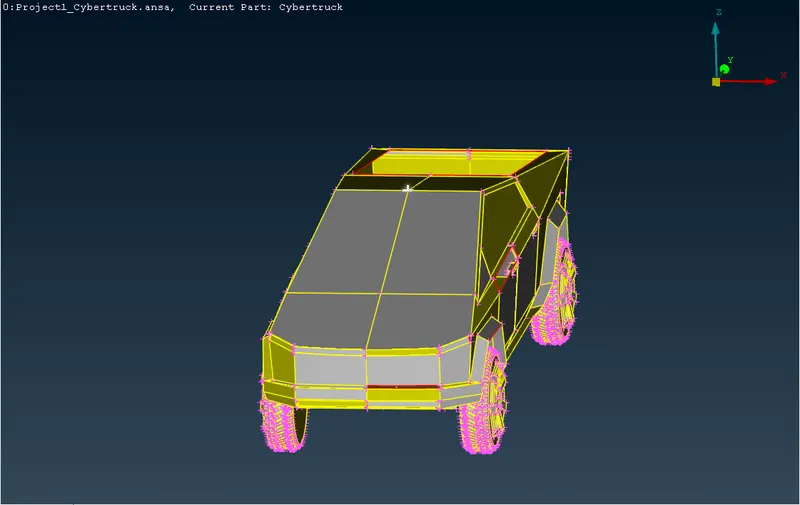
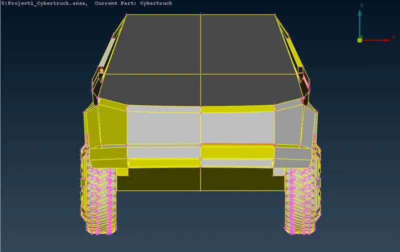
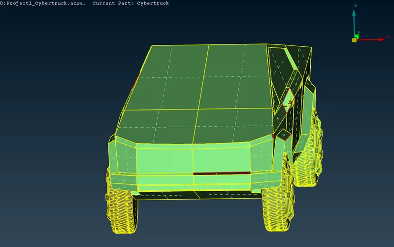
- Now delete the model from half portion to perform checks.
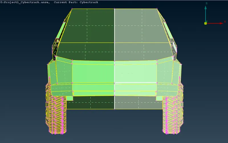
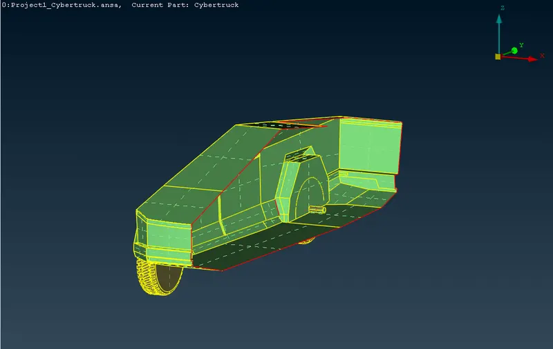
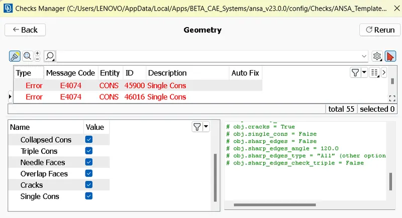
- After performing checks-geometry, a lot number of single cons were found out in different locations. All these single cons are filled with new faces to make double cons.
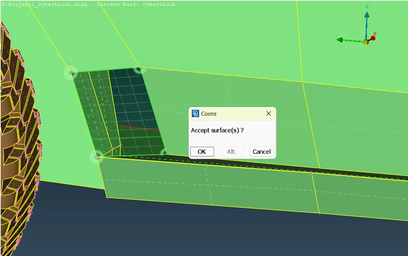
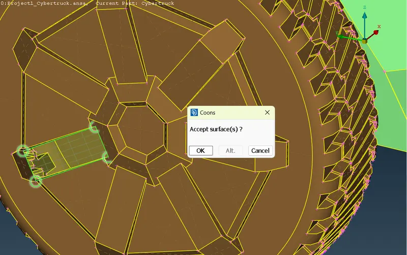
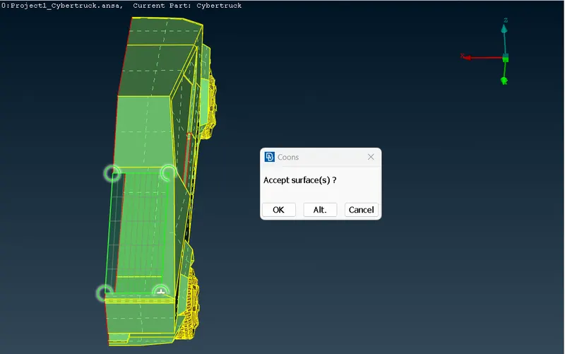
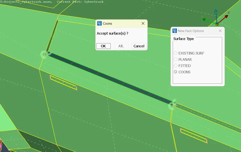
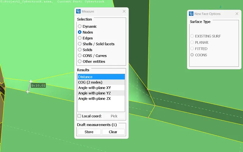
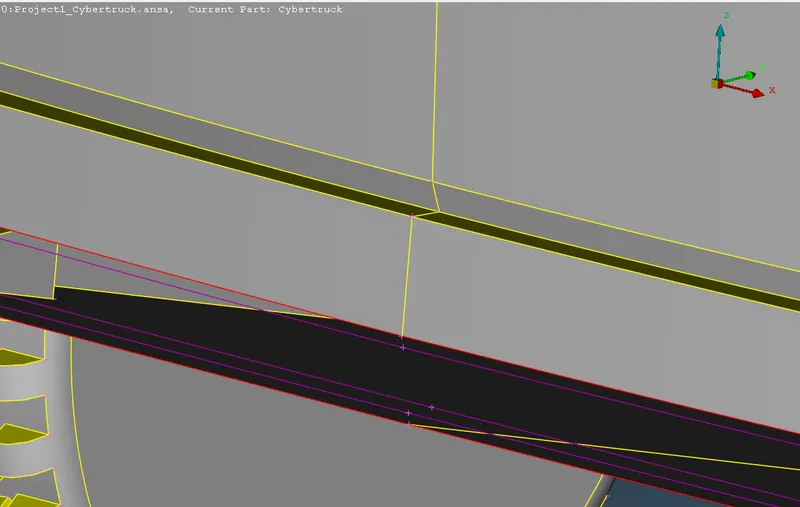
- In the model, small surfaces measured with 0.01 mm gap should be avoided as shown in figure.
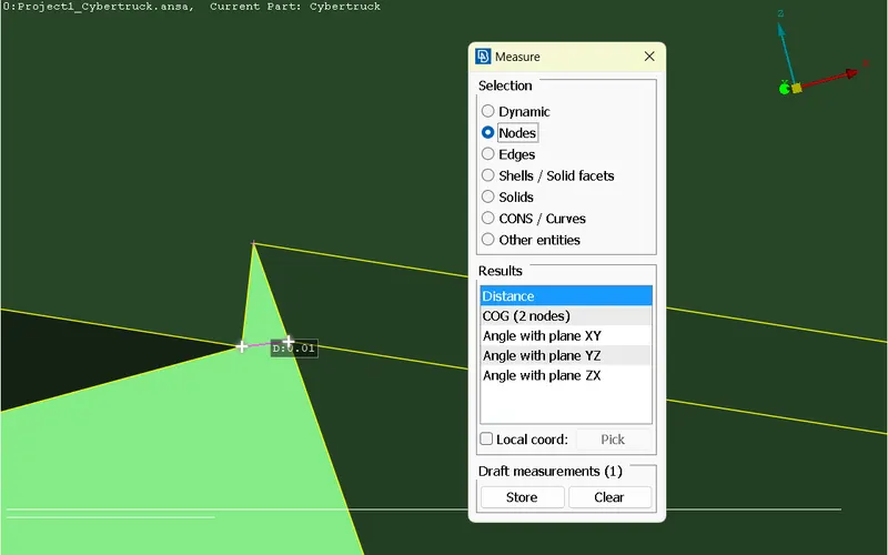
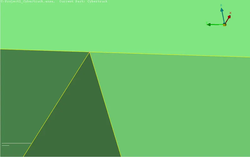
- Removed single cons nearer to front light.
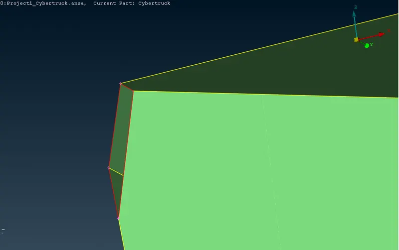
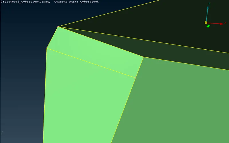
- In the model, small surfaces measured with 0.58 mm gap should be avoided as shown in the figure as these small gaps in mentioned PID’s will lead to error in meshes and multiple off elements.
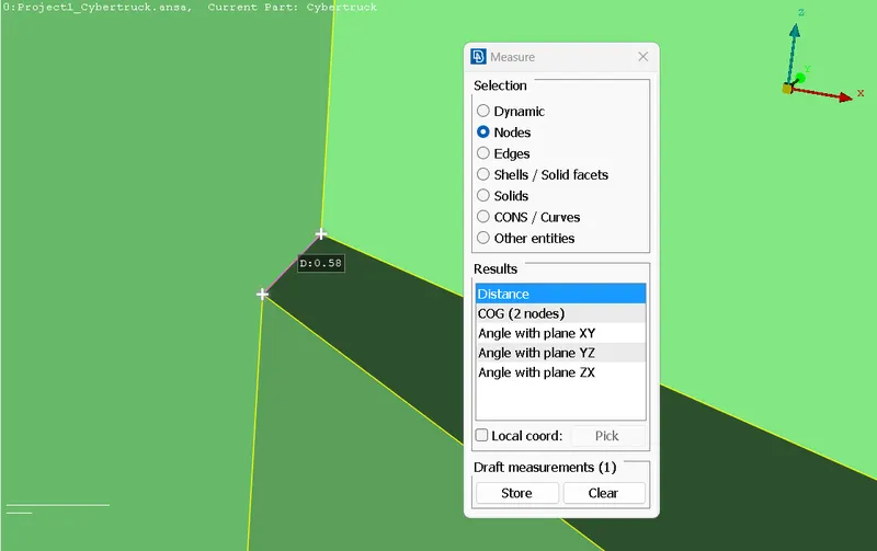
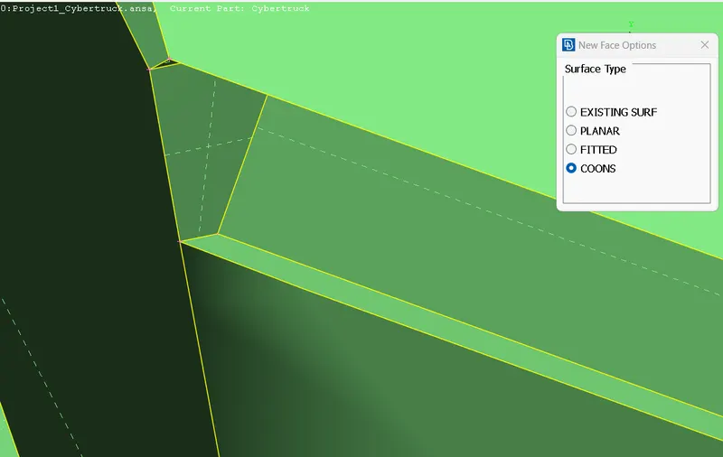
- Sharp edges in certain areas, especially on top right corner of front headlights may be lead to distorted meshes is corrected.
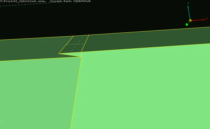
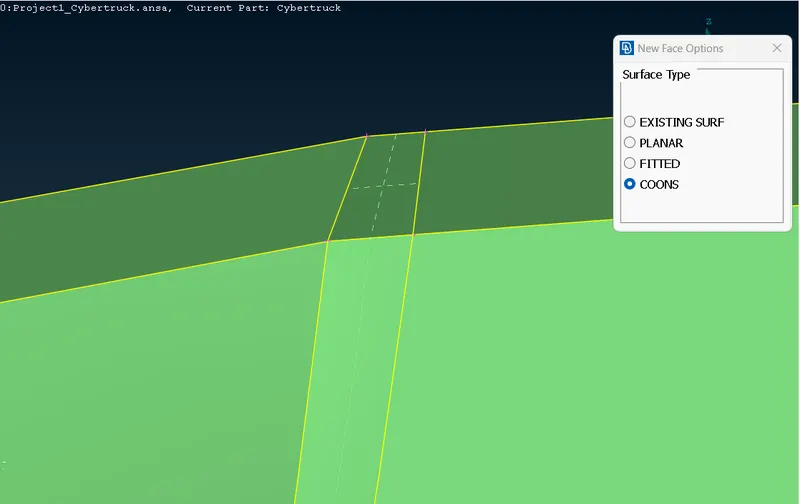
- Similarly bumper areas and areas nearer to ORVM locations(underneath A pillar) and tail light area are corrected.
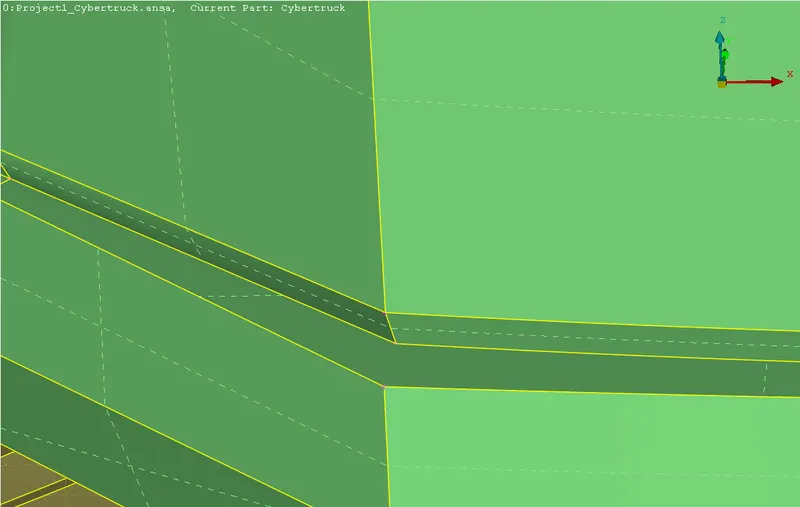
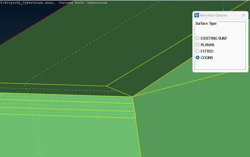
- Axle shafts where found to have dual surfaces overlapped which is removed.
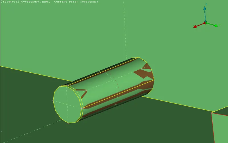
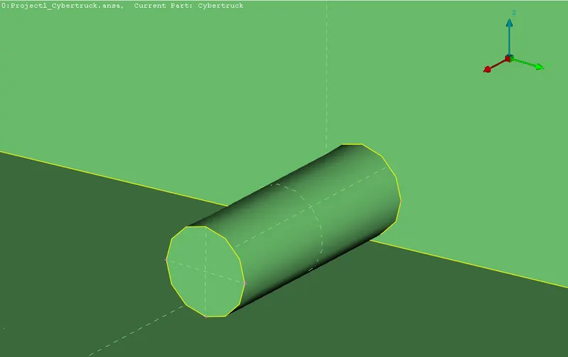
- Front grill area errors are corrected and prepared for meshing.
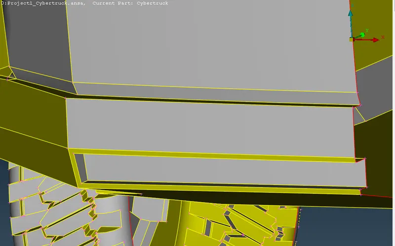
- Area under Co driver passenger door behind wheel mudflap was found to have certain distortions which may lead to improper meshing. These are corrected.
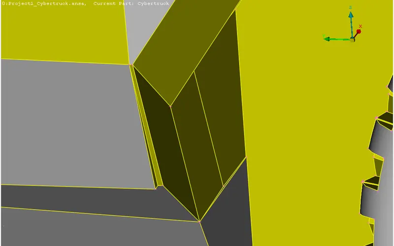
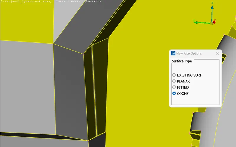
- Now symmetrical copy of the model is to be created. Here since project cut was not exactly in the mid plane, it is necessary to create symmetrical copy to avoid further errors during meshing. The entire car will be produced for meshing instead of half portion.
- After creating symmetric copy using Transform-Copy-symmetry symmetry is formed.
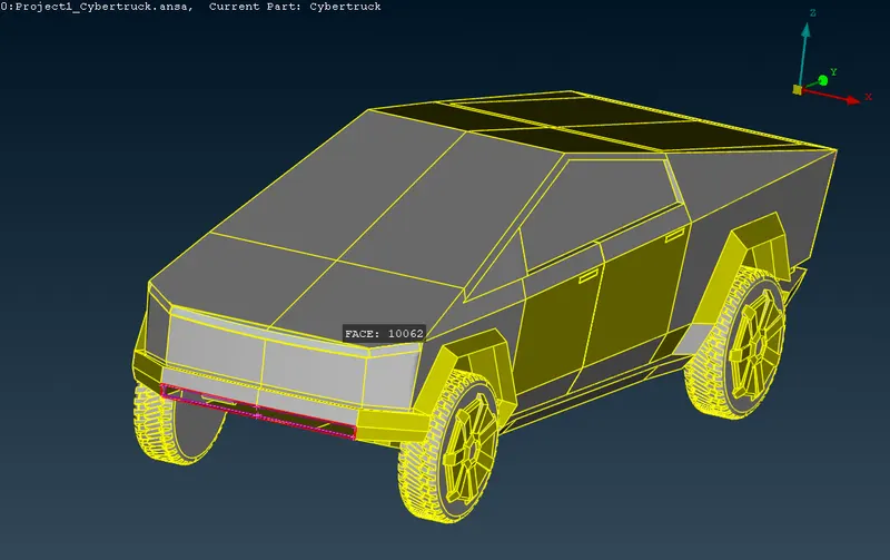
- Some gaps were found in the middle of bottom grill which are removed and using curves new surfaces are created.
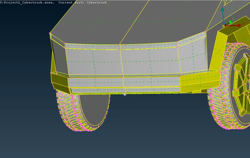
- Now check for geometric errors. No errors are found.
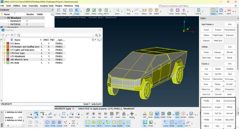
- Assign new PID’s and delete old PID’s.
SURFACE MESHING
- 1mm meshing carried out for light
1MM TARGET LENGTH
- Select Mesh parameters and set target length as 1mm and Select Quality Parameter and set minimum length as 0.5 mm and maximum length as 2mm.
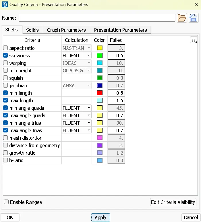
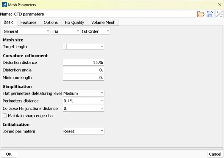
- Select Mesh deck and and select mesh parameters by selecting CONS of each PIDs and set length as 1mm and select macros and set as 1mm.
- Now select spot mesh and select face and middle click on mouse to see the meshes.
- Delete all off elements by Reconstruct option and grid movement.
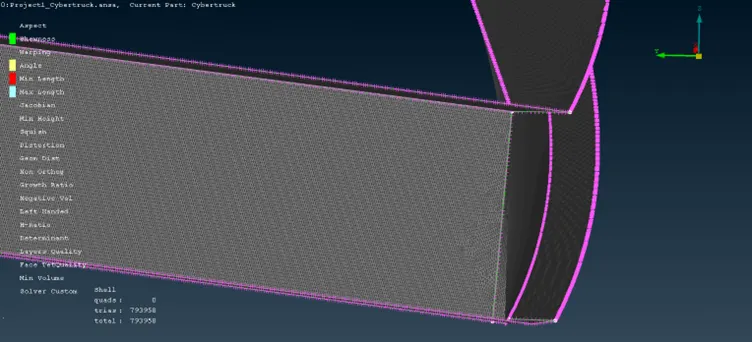
- 2mm meshing carried out for door gaps.
2MM TARGET LENGTH
- Select Mesh parameters and set target length as 2mm and Select Quality Parameter and set minimum length as 1mm and maximum length as 3mm.
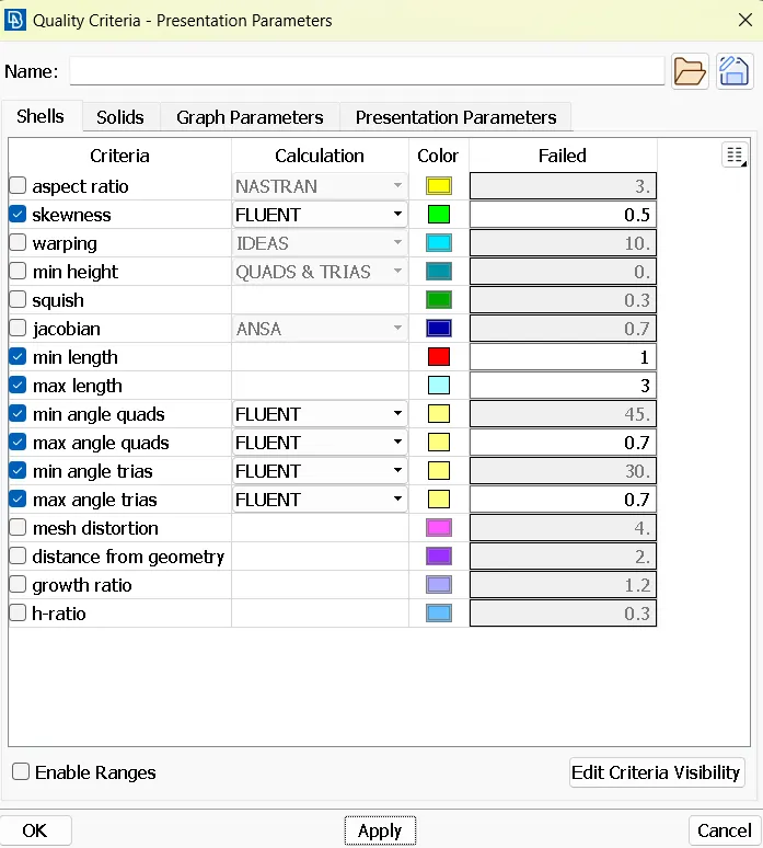
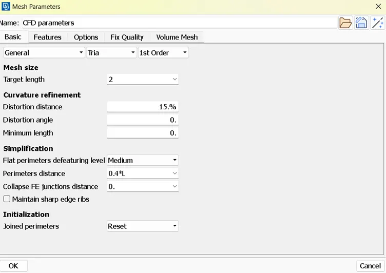
- Select Mesh deck and and select mesh parameters by selecting CONS of each PIDs and set length as 2mm and select macros and set as 2mm.
- Now select spot mesh and select face and middle click on mouse to see the meshes.
- Delete all off elements by Reconstruct option and grid movements.
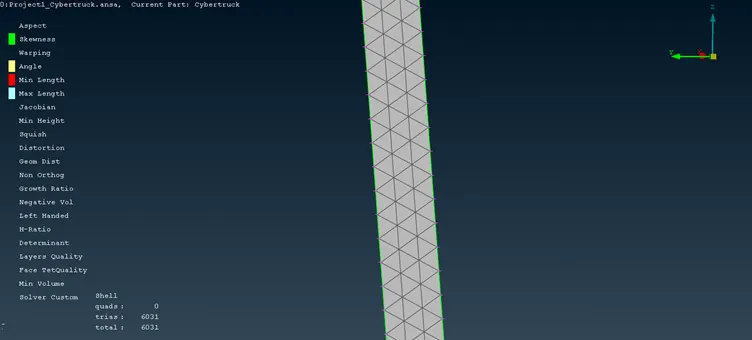
- 3mm meshing carried out for doors, wheels and tyres, bumper and mudflap area and finally windshield.
3MM TARGET LENGTH
- Select Mesh parameters and set target length as 3mm and Select Quality Parameter and set minimum length as 1 mm and maximum length as 5mm.
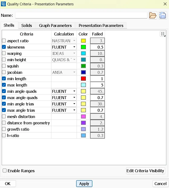
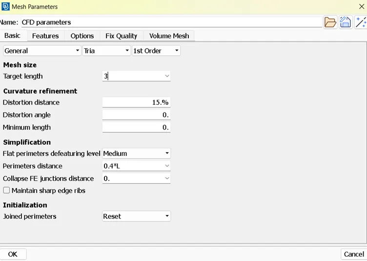
- Select Mesh deck and and select mesh parameters by selecting CONS of each PIDs and set length as 3mm and select macros and set as 3mm.
- Now select spot mesh and select face and middle click on mouse to see the meshes.
- Delete all off elements by Reconstruct option and grid movements.
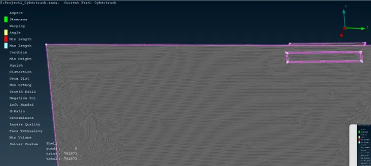
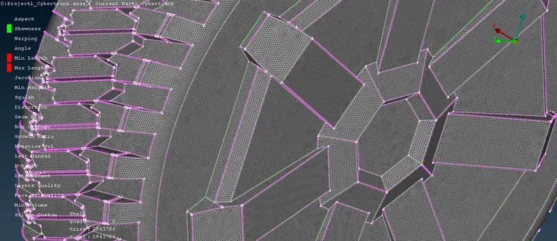
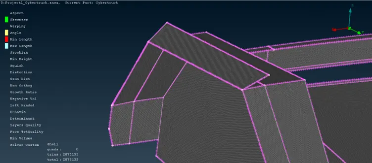
- In windshield area near to door gap region there are 2mm meshes. So range of meshes needs to be specified in location.
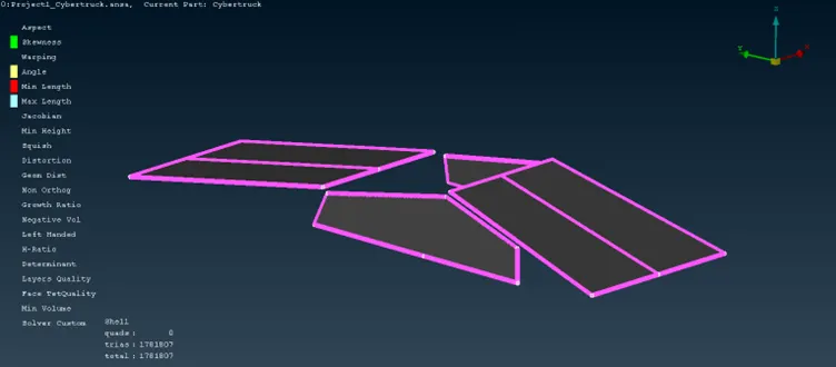
- 5mm meshing carried out for body.
5MM TARGET LENGTH
- Select Mesh parameters and set target length as 1mm and Select Quality Parameter and set minimum length as 0.5 mm and maximum length as 20 mm.
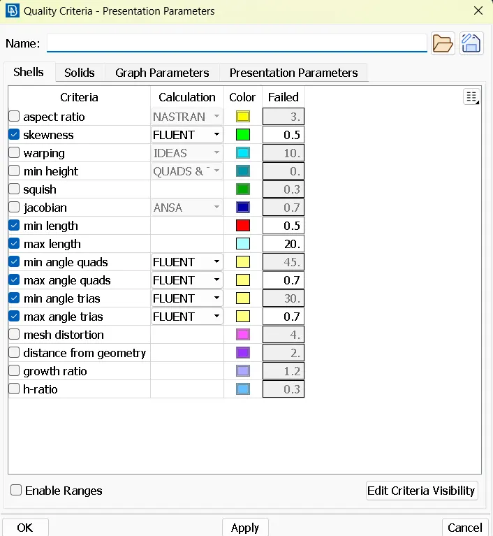
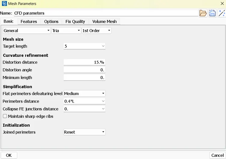
- Now select spot mesh and select face and middle click on mouse to see the meshes.
- Delete all off elements by Reconstruct option and grid movements.
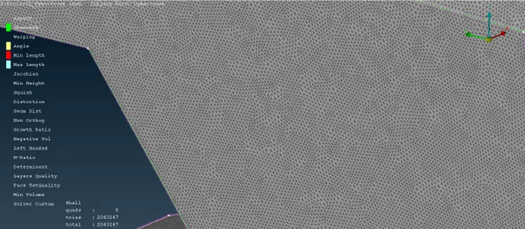
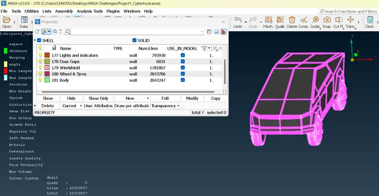
PREPARATION OF WINDTUNNEL
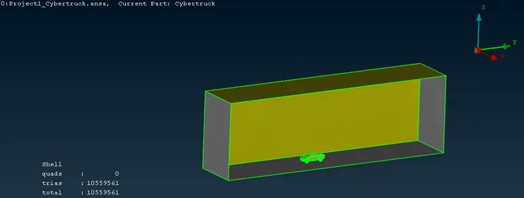
- Create new points by measuring length of car body. It was measured to be 6000 mm length as x. the front length of windtunnel should be 4x and length of rear end of windtunnel should be 6x. the side lengths on either side should be x distance and lower height can be just below the tyre and upper height can by 3x. at all these points create new points.
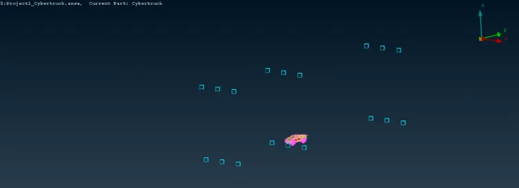
- And by Coon option create rectangular boxes.
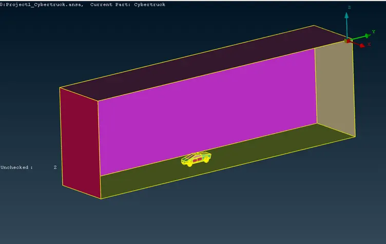
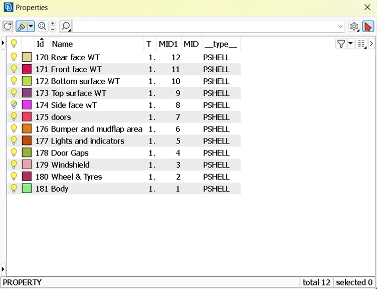
- Now create PIDs for each face of wind tunnel.
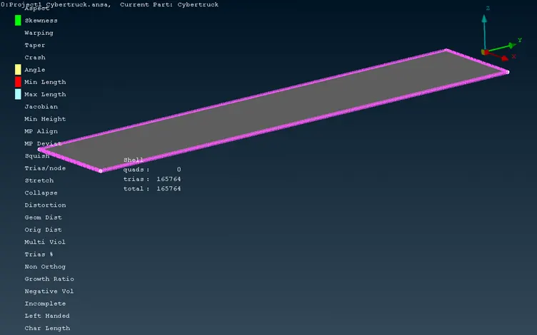
- Assign quality criteria for top and bottom surfaces.
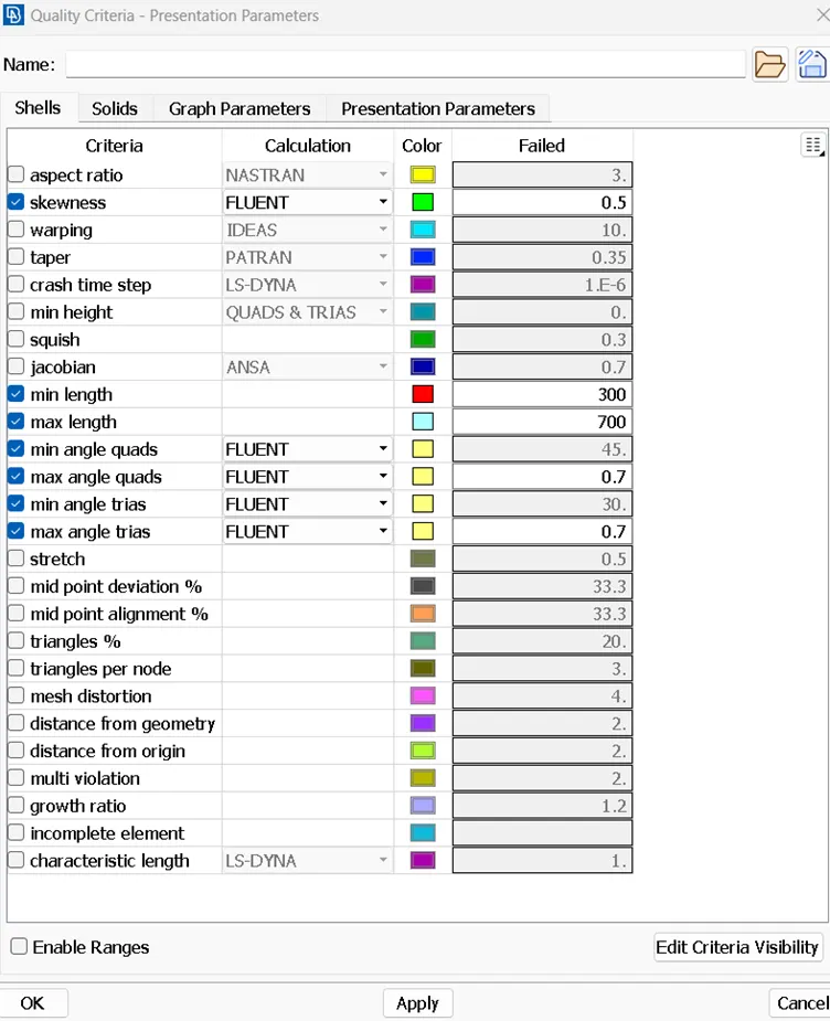
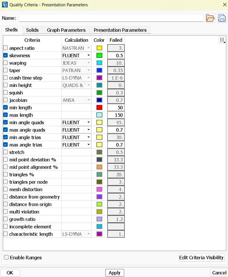
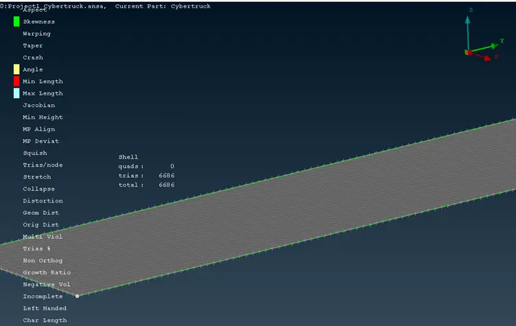
- Now mesh top and bottom surfaces according to each quality critreria.
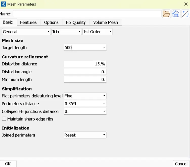
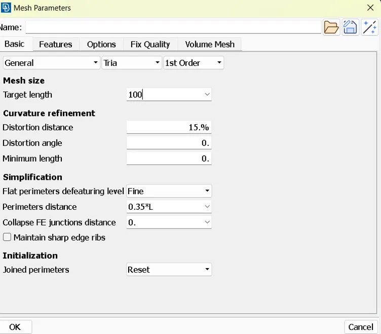
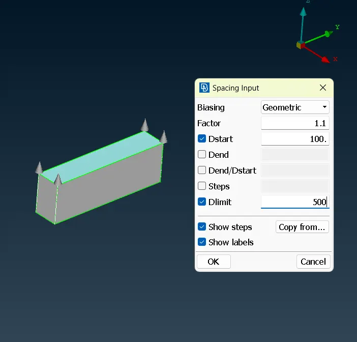
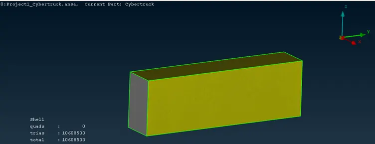
- Now on front and rear surfaces assign spacing option for meshing between 100 and 500 mm.
LEARNING OUTCOME:
- Lifelong Learning
- Modern Tool Usage
- Communication
RESULT:
- Checked for the geometrical errors and made appropriate volumes.
- Created and assigned PIDs to all shells.
- Performed surface mesh with the given target lengths as per PIDs.
Google drive link of the worked model: https://drive.google.com/drive/folders/1UaoiCB6tGSEyDLbMg2l8Mqkg-FDGZfew?usp=sharing
CONCLUSION:
Best results were obtained when mesh sizes were smaller, but increase in mesh elements is not appreciable as this may leads to more computation times while making volumetric meshes.