Project 1 : CFD Meshing for Tesla Cyber Truck
CHALLENGE REPORT :
AIM :
To check and solve all geometrical errors for the given model and assign appropriate PIDs and Perform meshing with the given Target length and element Quality criteria.
OBJECTIVE :
* To check and solve all geometrical errors on half portion of the given model.
* To assign the properties PIDs.
* To perform meshing with the Target length and element Quality criteria.
* After meshing the half model, Do symmetry to the other side.
* Meshing Wind tunnel volume with tetra elements .
Introduction :
ANSA :
- ANSA is a Computer-aided engineering tool for Finite Element Analysis and CFD Analysis widely used in the automotive industry. It is developed by BETA CAE Systems. The software is distributed world wide by a number of BETA CAE Systems subsidiaries and business agents.
- ANSA maintains the association between CAD geometry and the FE mesh. This means that the FE meshes are better representations of their geometric parents. Also it is easy to maintain and update any changes in the geometry by simply reworking the updated area instead of recreating the FE from scratch.
- It carries several proprietary algorithms for meshing suitable for both CFD and structural models. ANSA was initially standing for 'Automatic net generation for structural analysis' , but the software has gone beyond that very quickly. ANSA has broadly six menus which are used to do various activities those are: TOPO MESH, VMESH ,DECK-SOLVER, MORPH ,HBLOCK.
Different type of modules in ANSA :
- TOPO - Set of tools for Geometry clean-up and for setting up of PIDs.
- MESH - Tools to generate Surface Mesh or 2D Mesh.
- VOLUME MESH - To generate solid or 3D Mesh.
- SOLVER DECKS - Tools based on different solvers such as ABAQUS, RADIOSS ,ANSYS etc.
- MORPH - Advanced tool to capture geometry more accurately while meshing.
PROCEDURE :
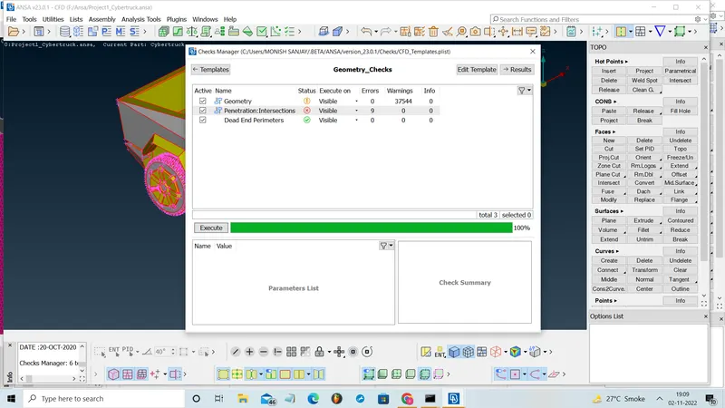
i) Applying Geomentry checkup:
* Select the check option.
* Enter the check manager and select the geomentry and exicute it.
* Clear all the geomentry and intersection errors.
ii) Clean-up of Geometry
- First we need to import the geometry model from the source folder.
- The geometry file contains lot of ir-regularities, discontnuities, so we need to patch all the missing and open surfaces in the geometry.
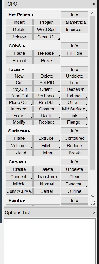
- This can be done by using the variours tools in the topo tab.
Some important tools to edit and coorect the patches in the model:
i) Faces (new, cut, intersect, Topo)
* The new option in the faces is used to create the new faces or surfaces by selecting the cons. It has four sub option like existing surf, planar, fitted, coons to create the surfaces depends on usage.
* Cut option is used to cut or separate the surfaces.
* Intersect option is used to correct the intersection error.
* Topo is used to auto correct some of the single coons and some geomentrical errors which can be corrected by the option.
ii) Coons (fill hole, project)
* The fill hole is similar to new option in faces, it is uaed to fill the surfaces if any open surfaces is present.
* Project is used to project the coons frome one surface to another surfaces.
iii) Hot points (insert, delete)
* The inset is used to insert the hot hots at the surfaces.
* Delete is used to delete the hot points.
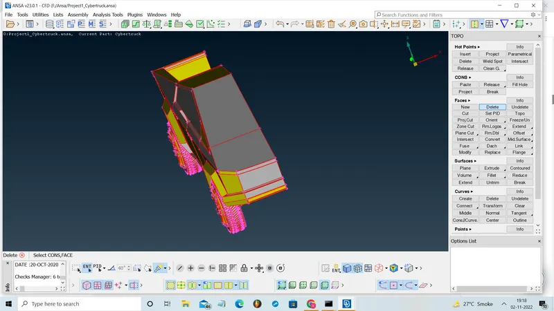
It looks difficult and time consuming process to do geomentry clean up for entire cyber truck model, so we can delete the half car model and then clear all geomentry error, assign the 2D meshing and we can make symmentry of the half model using transform option.
* It is too difficult to clear all the error at a time, so we can take each parts separately and we can clear the error.
* We are going to perform external flow analysis in wind tunnel, so we have make the entire model into single volume.
* Every parts after clearing the geomentric error, we wants to convert into single volume.
Clean-up of Geometry at each parts :
* Body :
--> In this part, there are lot of unnecessary surfaces which needs to be deleted and clear the intersection faces using the intersection option.
--> Just clear all the single coons and triple coons and make as single volume.
--> To clane up the floor part is difficult process and it can be done by deleting the small faces and create new faces in the deleted and open faces.
* Window
In windows there some unnecessary faces and overlap faces which create triple coons, so delete it and clear all the intersection.
* Lights
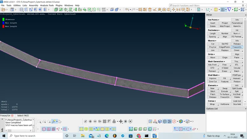
In these delete unneccessary parts and faces which is inside and make it as single volume.
* Rims and Tyres
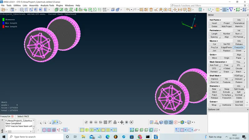
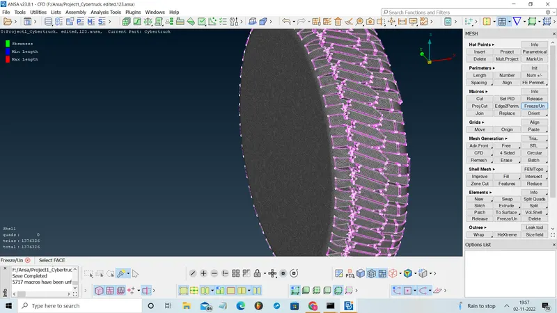
Delete the unneccessary faces and join the open faces and make it as single volume.
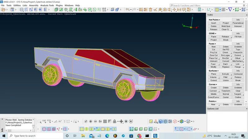
iii) PID assigning:
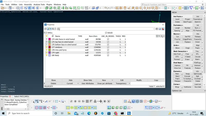
We need to create PID (Property ID) for all the surfaces like Body, Lights, Rims and Tyres, Window.
* Properties assining procedure
→ right click on the properties screen
→ select the new
→ select PSHELL
→ box will appeare
→ We have to assign the name.
- Similarly we wants to create based on requirement.
- The we want to assign the created PID 's to the respective surfaces required and we want to make sure that cross-hatches option is enabled.
- The following procedure are;
→ right click on the PID in properties
→ Select the apply option
→ Select the cross hatch present in the surface of the geometry
→ And middle click on the mouse.
- Similarly do for all the surfaces which we wants to assign.
iv) Surface mesh process:
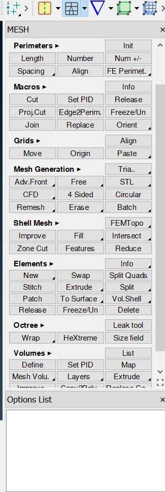
We wants to mesh the geometries part by part individually. (each part or component can be given different element length)
We can assume target elements for each parts,
* Body - 4 mm,
* Lights - 4 mm,
* Rims and Tyres - 2 mm,
* Window - 2 mm,
Meshing procedures are,
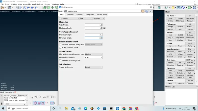
→ Assign the minimum and maximum target length by opening the Mesh parameters (Top of the screen), keep with CFD, tria, 1st order.
→ Next assign the perimeter in the spacing option in the perimeters table.
→ Assign the macros in the spacing option in the perimeters table.
→ After that to mesh go to Mesh generation (right side on the screen) and in the CFD table select the visile option.
We wants to do all the above procedure for each parts by isolating it as we assigned PIDs with differents element length.
v) Symmetry of the Geometry :
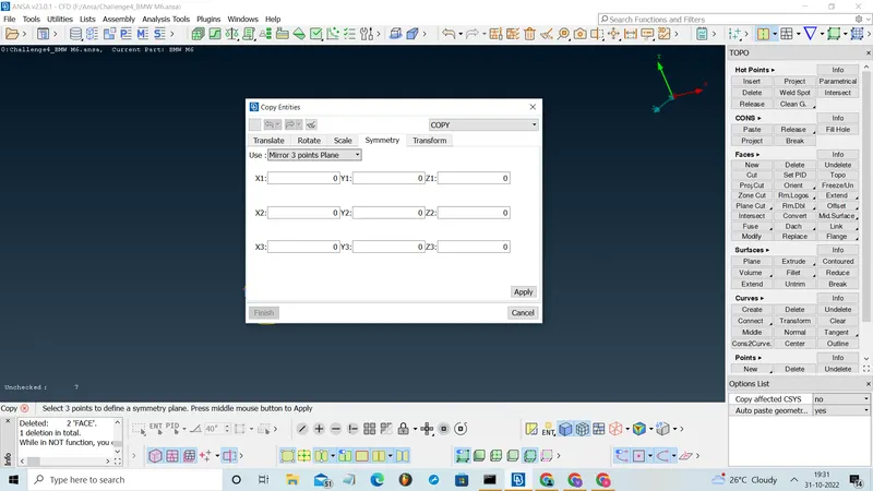
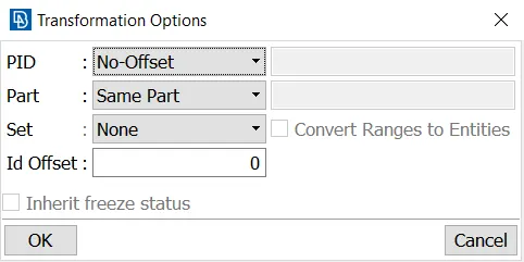
To set the symmetry for the model, we can use the transform option in the top of the window. In that select the copy and choose symmentry with mirror three piont plane and pick the three hot points on the model which will give perfect half of model. Middle clicking on it will produce the required symmetrical structure of the geometry.
vi) Wind Tunnel Creation and Meshing :
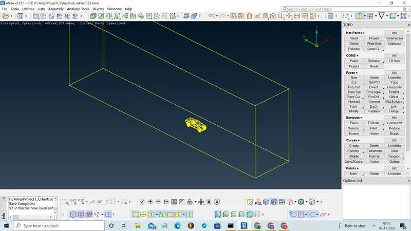
To create the Wind Tunnel around the geometry, first it is necessary to create boundary points with reference to the geometry. To create these boundary points, use RELATIVE option from the POINTS section. This option helps in creating a point relative to a selected point in any of the X, Y or Z direction.
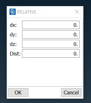
* Create the points by choosing the center point on the car and remaining points are created based on it,
Front Point - 26500mm,
Rear Point - 39350mm,
bottom Point - 1500 mm (from top reference point),
Side Point - 6000mm (Both sides of first Point).
* Join all the points by using the create option in the curve section and create the new face.
* Using the faces which is created, just offset to create above face and by joining the edges of the faces create side faces.
vii) Wind Tunnel Meshing :
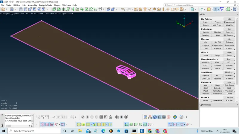
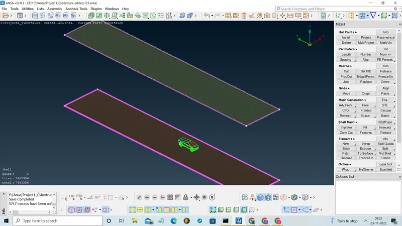
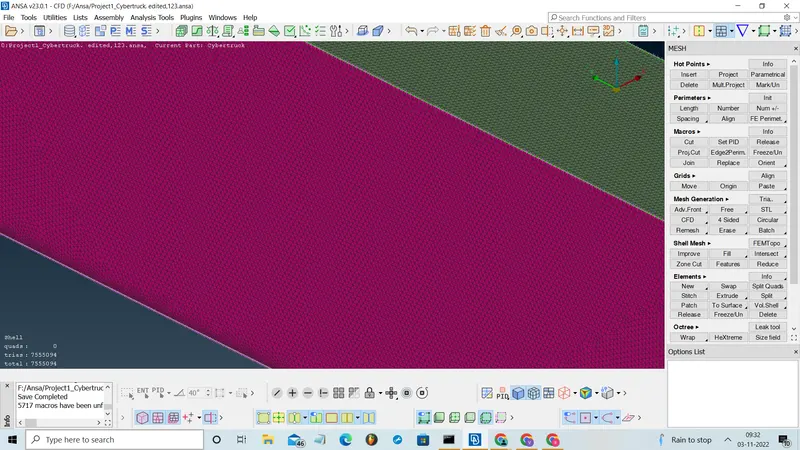
* As the Wind Tunnel is created, the next step is to mesh the Wind Tunnel Surface.
* For these mesh, the quality criteria of Maximum and Minimum lengths cannot be used. For this, the Mesh lengths mentioned below can be assigned in the Mesh Parameters pop-up window.
Top surface = 300 mm.
Bottom surface = 100 mm.
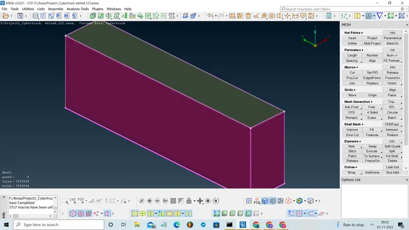
* Since the Mesh Lengths for Top and Base faces are different, for the Front, Rear and Side faces, variable mesh length is to be assigned which can be created by using Auto option in spacing from the perimeters section which required vertical edges of the Wind Tunnel Geometry is to be selected as represented below.
* And select the CFD and choose vissible to create mesh on it.
MESH OUTPUTS :
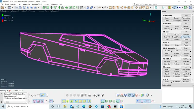
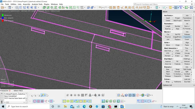
Body Part :
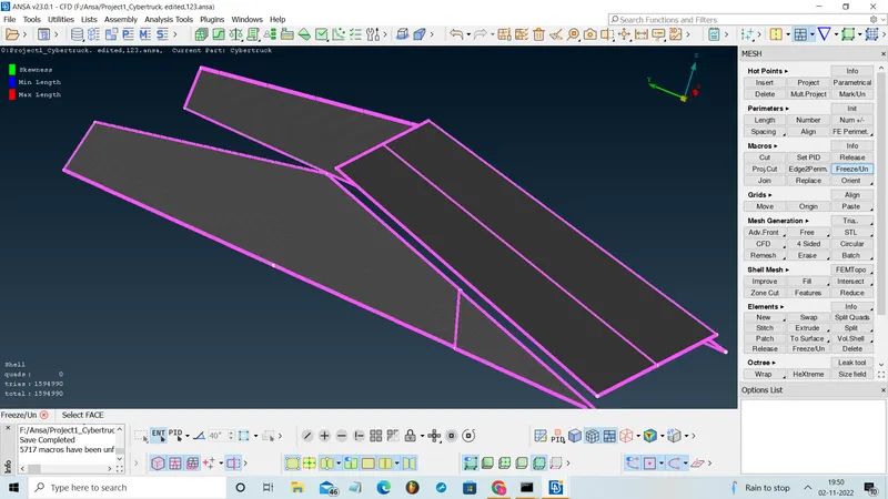
Windows :
Rims and tyres :
Lights :
Bottom face in wind tunel :
Top face in wind tunnel :
Side faces in wind tunnel :
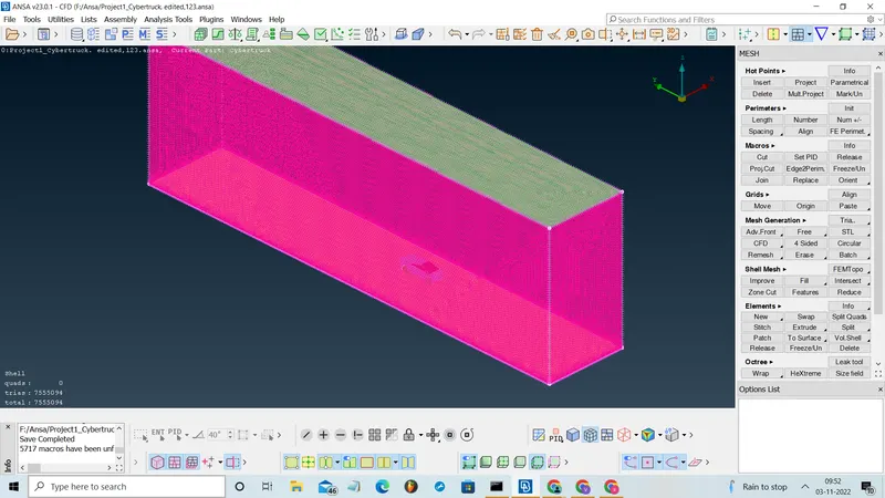
Wire frame of wind tunnel :
CONCLUSION :
The objective of these project like Topology Clean-up and meshing the geometry of a Tesla cyber truck with given mesh Target Lengths has been performed and further a Wind tunnel has been created around the geometry which can be used for physics simulations.
file link :
https://drive.google.com/file/d/11v65l4fb6Twd9UHMQ222BBvCPAUr5e44/view?usp=sharing