Project 1 : CFD Meshing for Tesla Cyber Truck
Objective:-
In this project, a Tesla Cybertruck in a wind tunnel will be meshed in ANSA. The geometry has multiple errors, these errors will be fixed. The mesh's element's lengths are same for each component of the geometry, but the mesh will be generated separately. The mesh length specifications are:
- Body - 5 mm
- Lights - 5 mm
- Rims and Tyres - 5 mm
- Window - 5 mm
Procedure:-
The geometry was imported into ANSA and this is the initial geometry:
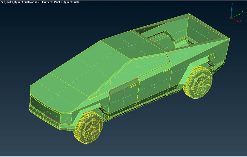
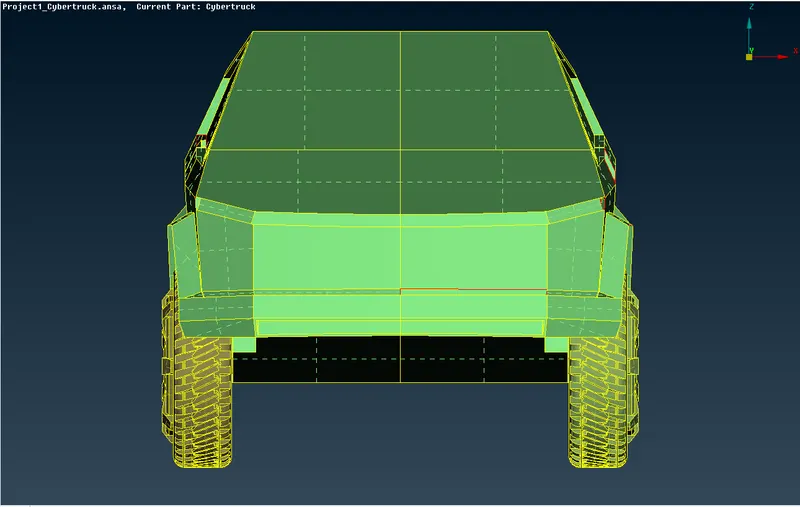
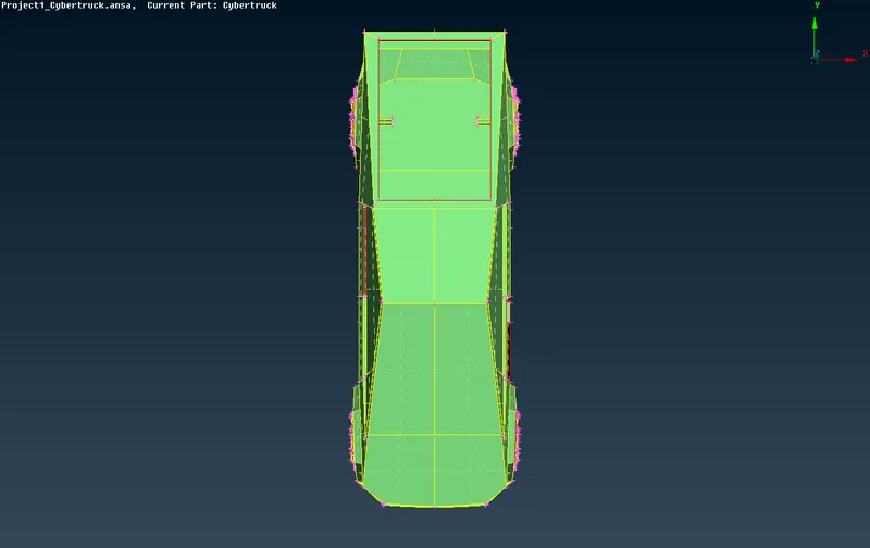
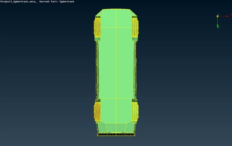
Since the car is symmetric, a cut was performed on the truck along the YZ plane. To ensure the cut was perfect, views of the car from all 4 sides is verified.
Front view,
Top view,
Bottom view,
Back view,
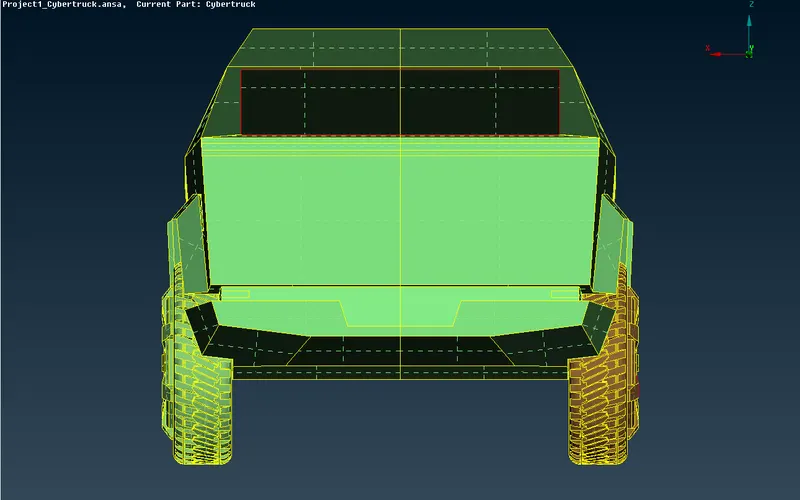
As we can see the cut is perfectly in the center.
This is the truck after deleting one half:
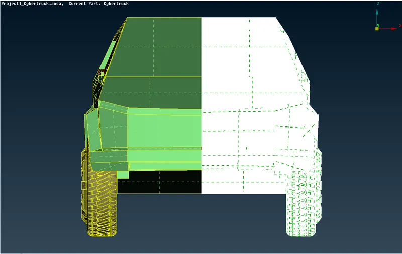
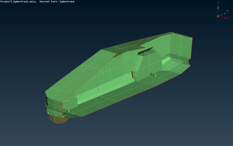
Wireframe View,
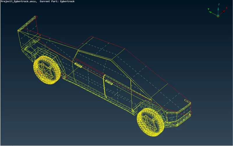
Upon further inspection, the errors are primarily of three types: single CONS, overlapped surfaces and extra surfaces.
These errors were rectified using the TOPO sidebar and all errors were rectifie.
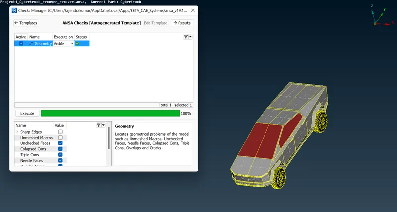
After all issues were fixed, the geometry checking tool was run (Checks -> Geometry). The default checks are chosen, and the following errors are checked. The checking process is started by clicking the Excecute button.
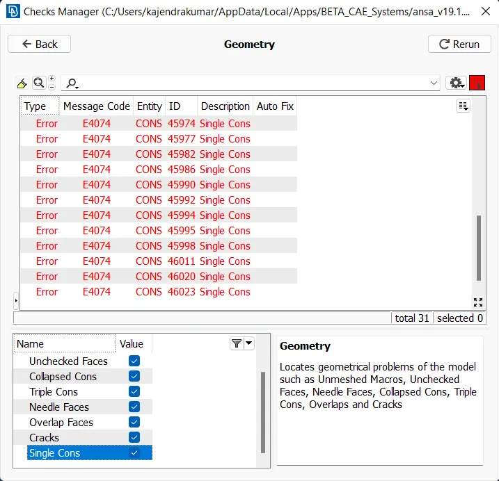
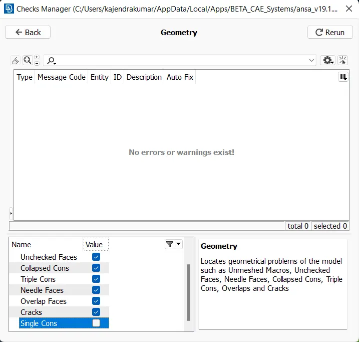
Since only one half of the model is being worked on, there are single cons along the symmetry plane. Running the geometry checking tool again without checking for single cons shows the following results:
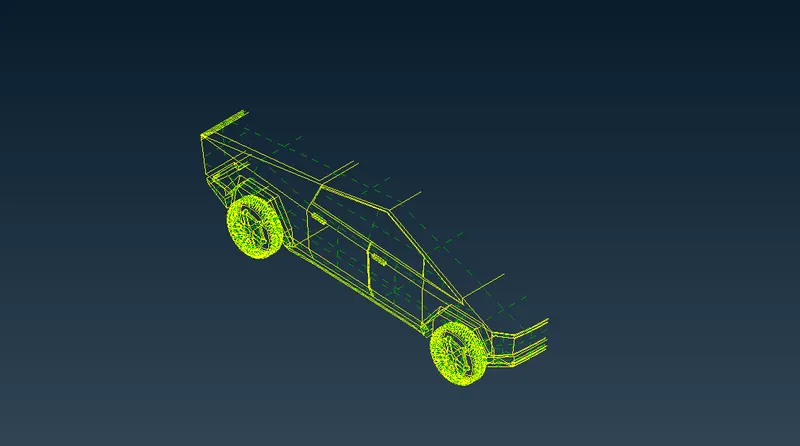
These are the double and triple CONS: (there are none)
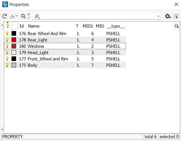
The model came with existing PIDs, these were created or modified/renamed to the following:
Picture of the car viewed by PIDs:
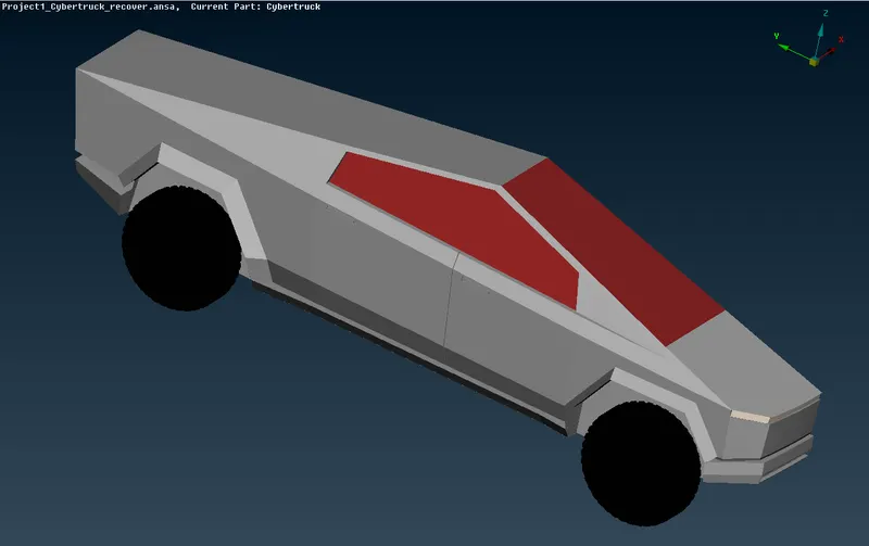
Surface Meshing:-
The preproccesing to the actual meshing process is complete. The surface mesh will be generated first under Classic Mesh Model. The PIDs were grouped by mesh size for convenience. For each size: perimeters, macros, mesh parameters and quality criterion were defined as follows.
Meshing : Rims And Wheels
Mesh Size: 5 mm
Parts of geometry/PID: rims and wheels
The quality of the mesh is defined in this step, this is done by going to Quality Criteria
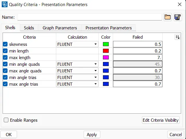
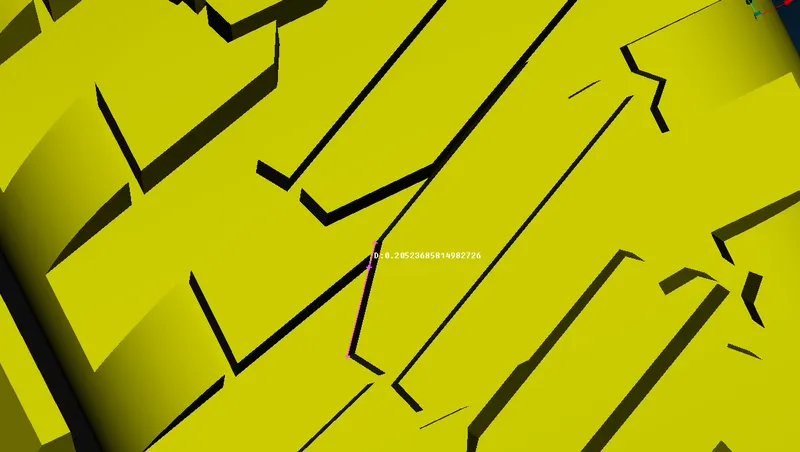
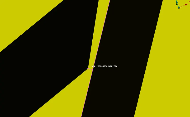
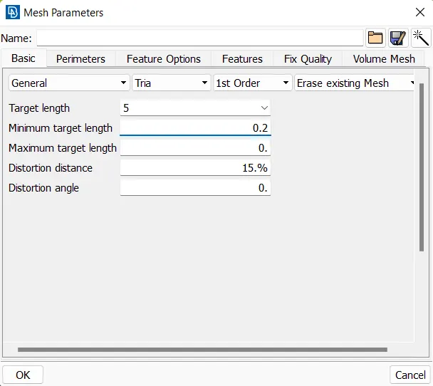
Note: the minimum length of 0.2mm is chosen to capture the gaps between the groves on the outer surface of the tyre, as seen below:
This is where the quality of mesh will be defined, this is done by going to: Mesh Parameters. The target length is entered as 5mm and the element type is set to Tria.
Go to Perimeters -> Length -> Perimeters, the whole geometry can be selected with the box select tool. After selection, the middle mouse button is pressed and mesh length (5mm) is entered.
The same process is repeated for Macros as well.
The mesh is generated for the following parameters using the spot mesh, this is done by going to
Mesh Generation -> Spot Mesh -> Visible
The quality criteria of the meshed elements are checked by switching over to the hidden view:
The off/bad elements are fixed using mesh tools such as: Join, Split, Move, Reconstruct and Paste.
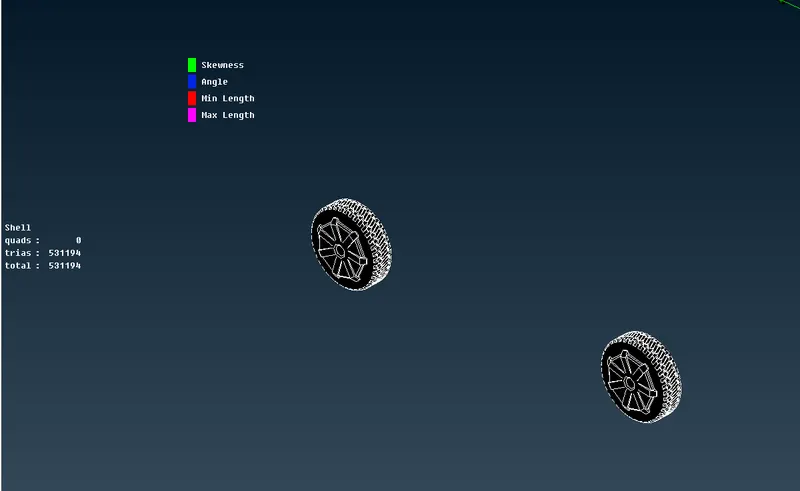
After no off elements are found in the meshed PIDs, the next set of PIDs are meshed.
Meshing : Lights
Mesh Size: 5 mm
Parts of geometry/PID: lights
The quality of the mesh is defined in this step, this is done by going to Quality Criteria
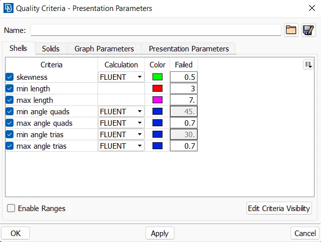
The minimum length is chosen from analysising the geometry in detail.
This is where the quality of mesh will be defined, this is done by going to: Mesh Parameters. The target length is entered as 5mm and the element type is set to Tria.
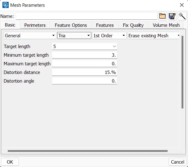
Go to Perimeters -> Length -> Perimeters, the whole geometry can be selected with the box select tool. After selection, the middle mouse button is pressed and mesh length (5mm) is entered.
The same process is repeated for Macros as well.
The mesh is generated for the following parameters using the spot mesh, this is done by going to
Mesh Generation -> Spot Mesh -> Visible
The quality criteria of the meshed elements are checked by switching over to the hidden view:
The off/bad elements are fixed using mesh tools such as: Join, Split, Move, Reconstruct and Paste.
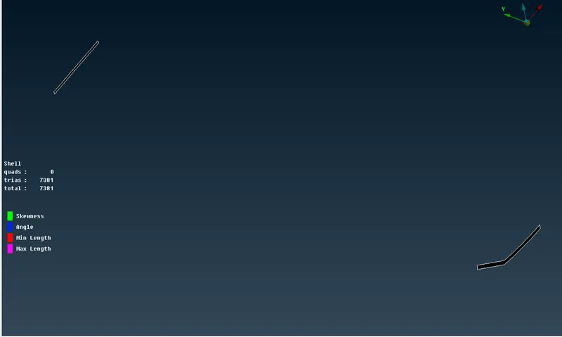
After no off elements are found in the meshed PIDs, the next set of PIDs are meshed.
Meshing : Windows
Mesh Size: 5 mm
Parts of geometry/PID: windows
The quality of the mesh is defined in this step, this is done by going to Quality Criteria
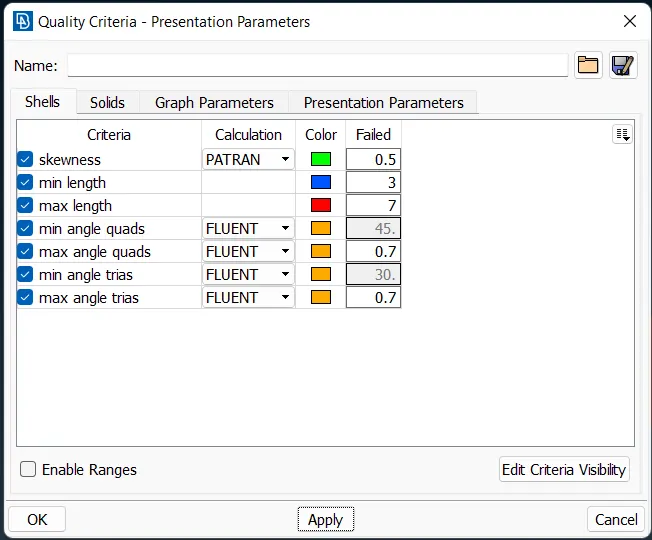
The minimum length is chosen from analysising the geometry in detail.
This is where the quality of mesh will be defined, this is done by going to: Mesh Parameters. The target length is entered as 5mm and the element type is set to Tria.
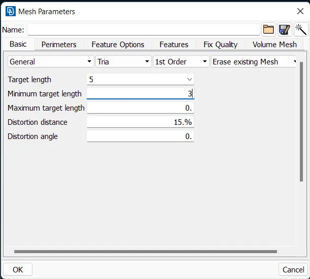
Go to Perimeters -> Length -> Perimeters, the whole geometry can be selected with the box select tool. After selection, the middle mouse button is pressed and mesh length (5mm) is entered.
The same process is repeated for Macros as well.
The mesh is generated for the following parameters using the spot mesh, this is done by going to
Mesh Generation -> Spot Mesh -> Visible
The quality criteria of the meshed elements are checked by switching over to the hidden view:
The off/bad elements are fixed using mesh tools such as: Join, Split, Move, Reconstruct and Paste.
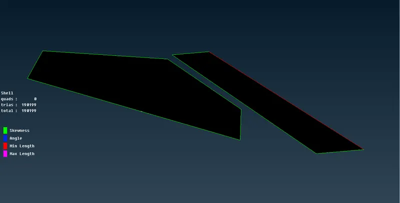
After no off elements are found in the meshed PIDs, the next set of PIDs are meshed.
Meshing : Body
Mesh Size: 5 mm
Parts of geometry/PID: body
The quality of the mesh is defined in this step, this is done by going to Quality Criteria
The minimum length is chosen from analysising the geometry in detail.
This is where the quality of mesh will be defined, this is done by going to: Mesh Parameters. The target length is entered as 5mm and the element type is set to Tria.
Go to Perimeters -> Length -> Macros, the whole geometry can be selected with the box select tool. The edges in contact with other PIDs are deselected. The middle mouse button is pressed and mesh length (5mm) is entered.
The same process is repeated for Perimeters as well.
The mesh is generated for the following parameters using the spot mesh, this is done by going to
Mesh Generation -> Spot Mesh -> Visible
The quality criteria of the meshed elements are checked by switching over to the hidden view:
The off/bad elements are fixed using mesh tools such as: Join, Split, Move, Reconstruct and Paste.
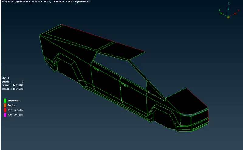
No eff elements are present in the body.
Mirror
Now, the surface has been meshed for the half body. The body has to be mirroed now. This is done by going to:
Transform -> Copy -> Entities
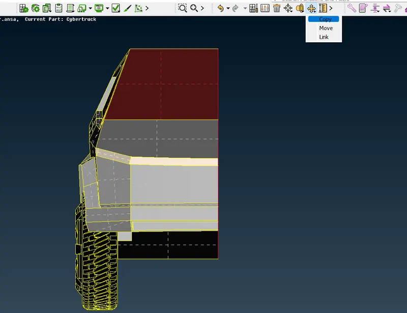
Shift + left click drag to select all entities:
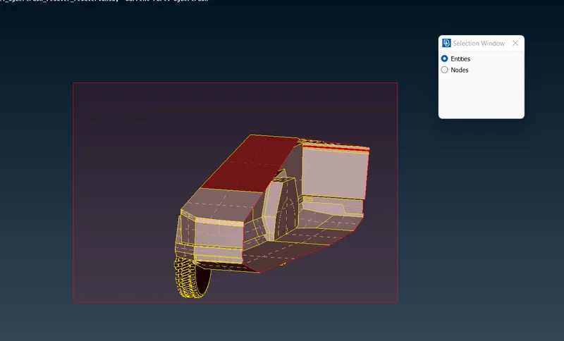
Click the middle mouse button to open the copy menu. Select three points on the symmetry plane of the car (or on the single cons)
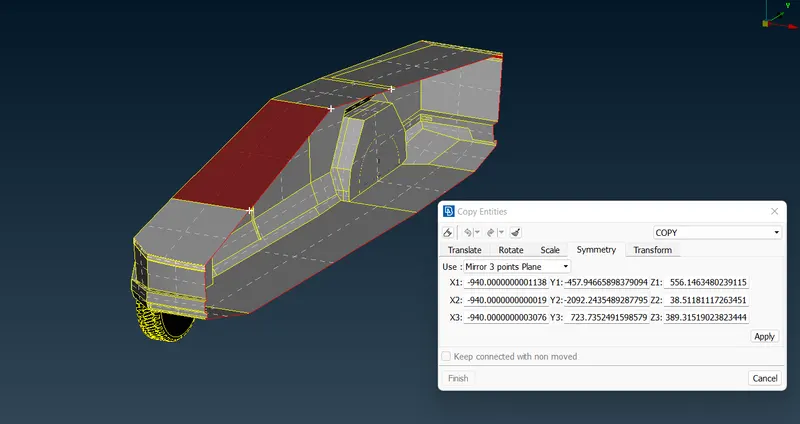
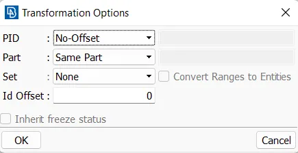
Click on OK, and after verifying the mirror is correct. Click on Finish to generate the copy.
The single cons are not fixed yet, they can be fixed by pasting the single cons together. This is the final geometry after pasting:
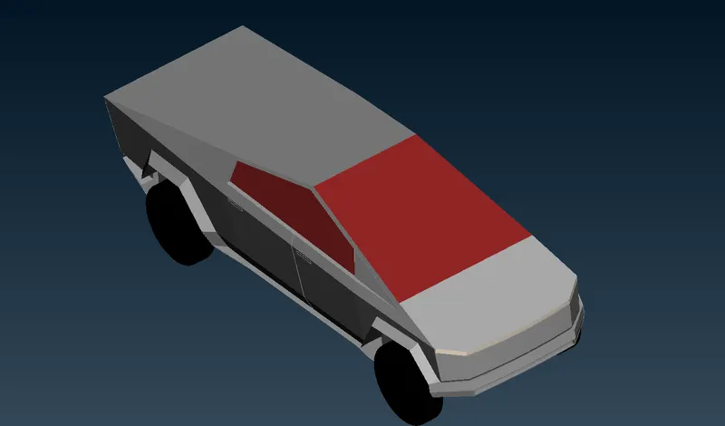
After pasting, a final geometry check is performed and no errors were found:
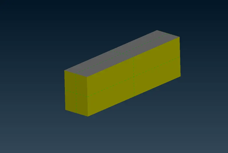
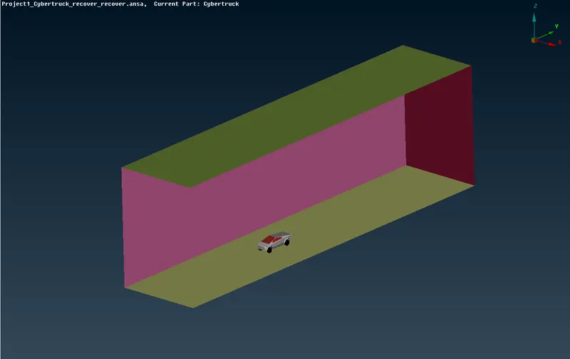
Surface meshing for the car is complete. A wind tunnel is used for CFD simulations, and has to be created in ANSA. The wind tunnel is a cuboid, and the car is placed inside it. The inlet of the wind tunnel is 4 times the charecteristic length of the car from the front of the car, the outlet of the wind tunnel is 6 times the charecteristic length of the car from the back of the car. The height of the wind tunnel is 3 times the charecteristic length of the car from the top of the car. While, the width of the wind tunnel is 1 time the charecteristic length of the car from the sides of the car.
For this truck, the charecteristic length was measured to be ~5800mm.
Using the above information, multiple vertices of the wind tunnel were created using: TOPO -> Points -> Relative
These points were joined to form a linear curve using: TOPO -> Curves -> Create
The curves were used to create surfaces using: TOPO -> Faces -> New
This is the resulting wind tunnel:
Hiding the front and left side to see the car:
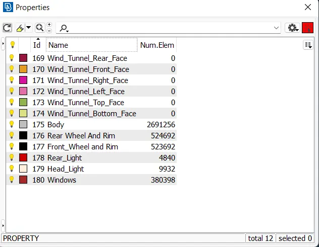
The curves and points created were then removed. PIDs were created for all surfaces of the wind tunnel.
The surfaces of the wind tunnel have to be meshed now.
Meshing : Wind Tunnel Faces
Mesh Size: 100mm
Parts of geometry/PID:
Wind Tunnel_top
Wind Tunnel_Bottom
Wind Tunnel_Left Face
Wind Tunnel_Right Face
Wind Tunnel_Front Face
Wind Tunnel_Rear Face
The quality of the mesh is defined in this step, this is done by going to Quality Criteria
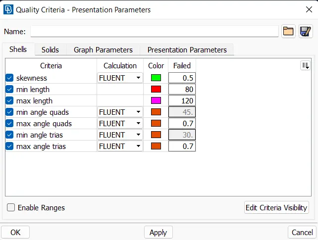
This is where the quality of mesh will be defined, this is done by going to: Mesh Parameters. The target length is entered as 100mm and the element type is set to Tria.
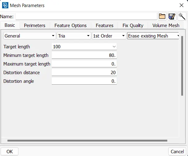
Go to Perimeters -> Length -> Perimeters, the top plane's edges are selected. After selection, the middle mouse button is pressed and mesh length (100mm) is entered.
The same process is repeated for Macros as well.
The mesh is generated for the following parameters using the spot mesh, this is done by going to
Mesh Generation -> Spot Mesh -> Visible
The Mesh quality was not checked as quality of elements at the boundaries do not matter as no data is obtained near the planes.
(Note: I've chose same mesh length for all wind tunnel faces, Instead go for variable mesh sizing,because that variable mesh sizing crash the ANSA)
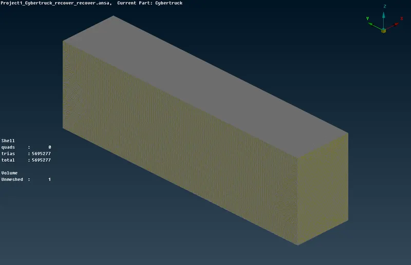
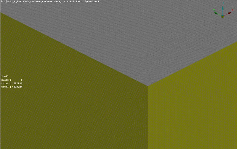
The surface mesh is now complete for both car and the wind tunnel, there are about 5.7 million elements, all of them are trias.
Front view with lights and front wheel
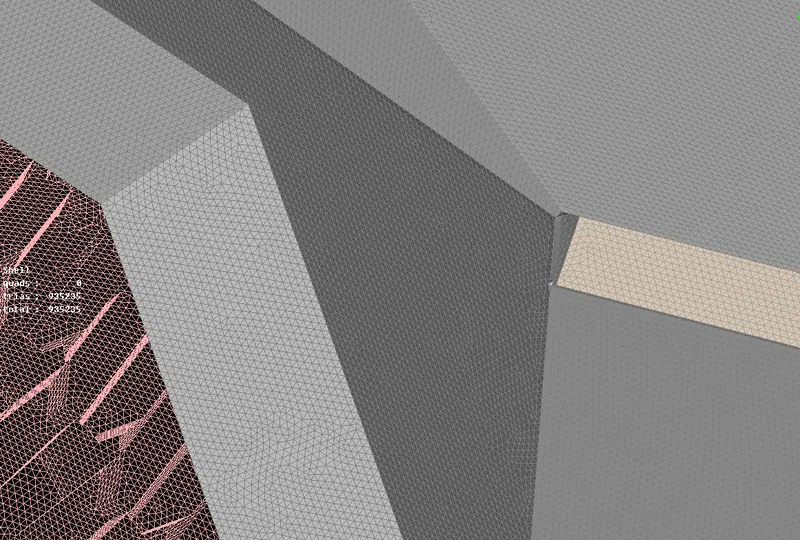
Back view with lights and back wheel,
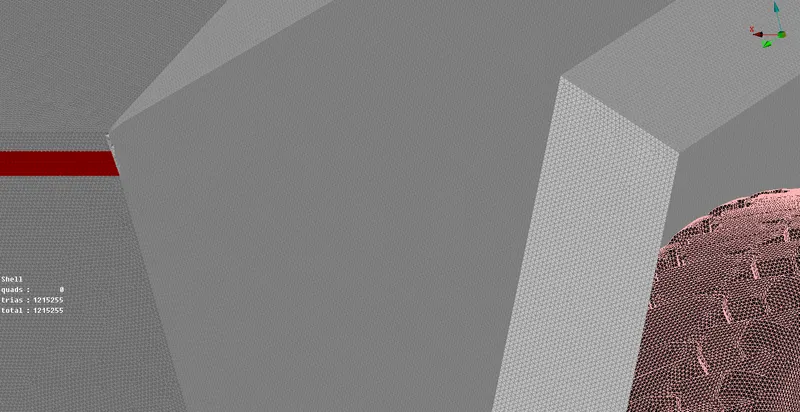
Windows,
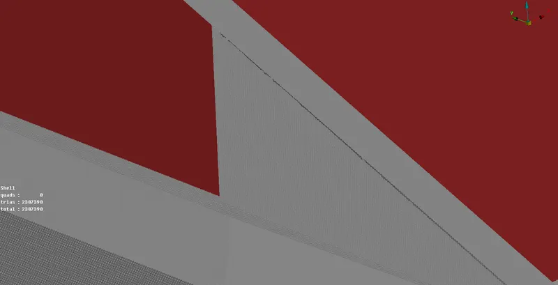
wind tunnel,
Volumetric Meshing
Go to V.Mesh tab,
Volumes -> Define ->
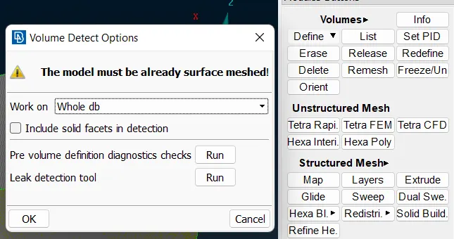
Click on OK, and ANSA will generate volumes automatically.
Click on each volume and view its preview, the required volumes (volumes where fluid flow will occur) are renamed and the other volumes are deleted.
After deletion, these volumes remain:
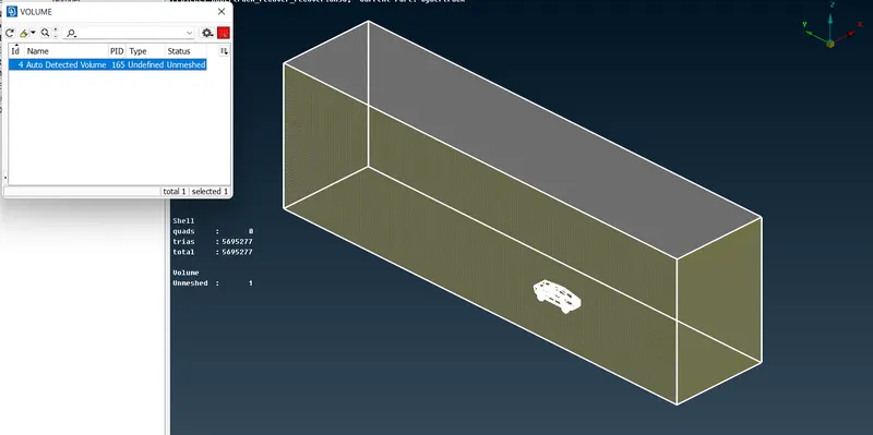
(Note: the volumetric mesh was not generated for this project as it requires a lot of computational resources.)
Conclusions and Observations
1. ANSA is a powerful meshing tool and a proper workstation is required to mesh complex geometry such as this truck.
2. There were multiple instances during this project, that ANSA would freeze for 10-20 minutes while it was meshing any surface.
3. SpotMesh produces a lot of off elements, and they were fixed using the Reconstruct tool which took a lot of time and memory.
4. Volume meshing couldn't be performed due to high performance requirements, and lack of computer memory. ANSA crashed a few times while trying to generate volumetric mesh and memory used by ANSA exceeded 5.5 GB.
Final Output File :- https://drive.google.com/file/d/1mALnAN7ppk4F7CyedbVITfi8DJ3kqul6/view?usp=sharing